
VP18 - Recepteur Kramer - Notice d'utilisation et mode d'emploi gratuit
Retrouvez gratuitement la notice de l'appareil VP18 Kramer au format PDF.
| Type de produit | Amplificateur de distribution RGBHV 1:18 |
| Marque | Kramer |
| Modèle | VP18 |
| Catégorie | Récepteur / Distributeur |
| Nombre d'entrées | 1 (RGBHV) avec bouclage possible |
| Nombre de sorties | 18 (5 jeux de 5 sorties pour VP-18, 3 sorties pour les dernières) |
| Connecteurs | BNC pour entrées (RGBHV) et sorties (RGBHV) |
| Bande passante | 360 MHz (-3 dB) |
| Rapport signal/bruit vidéo | 71 dB |
| Diaphonie | -65 dB |
| Distorsion différentielle | 0.12% |
| Phase différentielle | 0.15° |
| Facteur K | < 0.05% |
| Contrôles | Niveau sortie (-1.4 à +1.7 dB), EQ (0 à 2.3 dB à 5 MHz) par groupes de 5 sorties ; couplage AC/DC et impédance (Hi-Z/75 Ω) par entrée |
| Alimentation | 230 VAC, 50/60 Hz, 7 VA max (115 VAC pour USA) |
| Dimensions (L x P x H) | 19 pouces (483 mm) x 7 pouces (178 mm) x 3U (133 mm) |
| Poids | 6 kg (13.2 lb) |
| Montage en rack | Oui, 19 pouces, 3U, avec oreilles de rack fournies |
| Accessoires inclus | Cordon d'alimentation, manuel d'utilisation, patins en caoutchouc |
| Température de fonctionnement | Non spécifiée, mais adapté à un environnement de bureau |
| Entretien et nettoyage | Débrancher avant nettoyage ; utiliser un chiffon sec et doux ; ne pas utiliser de liquides ni d'aérosols |
| Sécurité | Utiliser une prise mise à la terre ; ne pas ouvrir le boîtier ; confier toute réparation à un technicien agréé |
| Réparabilité | Réparation par un centre agréé Kramer ; garantie 3 ans pièces et main-d'œuvre |
FOIRE AUX QUESTIONS - VP18 Kramer
Questions des utilisateurs sur VP18 Kramer
0 question sur cet appareil. Repondez a celles que vous connaissez ou posez la votre.
Poser une nouvelle question sur cet appareil
Téléchargez la notice de votre Recepteur au format PDF gratuitement ! Retrouvez votre notice VP18 - Kramer et reprennez votre appareil électronique en main. Sur cette page sont publiés tous les documents nécessaires à l'utilisation de votre appareil VP18 de la marque Kramer.
MODE D'EMPLOI VP18 Kramer
Kramer Electronics, Ltd.
USER MANUAL
RGBHV Distribution Amplifiers
Models:
VP-10
VP-15
VP-18
IMPORTANT: Before proceeding, please read paragraph entitled "Unpacking and Contents"
Table Of Contents
Section Name Page
1 INTRODUCTION 3
1.1 A Word on VGA/XGA/RGBHV Distribution / Line Amplifiers 3
1.2 Handling Graphics Signals 3
1.3 Factors Affecting Quality of Results 5
2 HOW DO I GET STARTED 5
3 UNPACKING AND CONTENTS 6
3.1 Optional Accessories 6
4 RGBHV DISTRIBUTION AMPLIFIER 7
4.1 Getting to know your VP-10/15/18 Distribution Amplifier 7
5 INSTALLATION 9
5.1 Rack Mounting 9
5.2 Connecting to RGBHV Devices 9
6. USING THE AMPLIFIER 9
6.1 Typical Application 9
6.2VP-10/15/18 preset 10
6.3 Handling signal losses 10
6.4 Other Uses 11
7 SPECIFICATIONS 12
8 TROUBLESHOOTING 12
8.1 Power and Indicators 12
8.2 RGBHV Signal 13
Limited Warranty 14
List Of Illustrations
Figure Description
1 VP-10/15/18 Front/Rear Panel Features 8
List Of Tables
Table Description
1 VP-10/15/18 Front/Rear Panel Features 8
1 INTRODUCTION
Congratulations on your purchase of this KramerRGBHV Distribution Amplifier Since 1981, Kramer has been dedicated to the development and manufacture of high quality video/audio equipment. The Kramer line has become an integral part of many of the best production and presentation facilities around the world. In recent years, Kramer has redesigned and upgraded most of the line, making the best even better. Kramer's line of professional video/audio electronics is one of the most versatile and complete available, and is a true leader in terms of quality, workmanship, price/performance ratio and innovation. In addition to the Kramer line of high quality RGBHV Distribution Amplifiers, such as the one you have just purchased, Kramer also offers a full line of high quality line amplifiers, switchers, processors, interfaces, controllers and computer-related products. This manual includes configuration, operation and option information for the VP-10, VP-15, VP-18 amplifiers, all similar in function and structure. The VP-18 amplifier will be described, but the others are similar except in their number of outputs.
1.1 A Word on VGA/XGA/RGBHV Distribution / Line Amplifiers
VGA/XGA/RGBHV distribution amplifiers distribute one or more signals to several users. They vary in the number of inputs, looping capability, programming capability, number of outputs, operating format, bandwidth and input/output coupling. VGA/XGA/RGBHV distribution amplifiers are used to distribute one source to several acceptors (wide screen projectors, format converters, etc.) for simultaneous recording or monitoring of one source, with no discernible signal degradation. These machines excel in very large bandwidth (some approaching 400Mhz) and very good linearity, making them usable for even the highest graphics standards. A good quality distribution amplifier amplifies the incoming signal, may pre-compensate the signal for potential losses (resulting from the use of long cables, noisy sources, etc.) and generates several identical buffered and amplified outputs. The front panels of these Kramer amplifiers are designed to be simple to operate. Typical applications of the machines are: computer graphics distribution in classes, point of sale and multimedia studios, displaying computer graphics before large audiences using the data input of a wide screen video projector.
1.2 Handling Graphics Signals
A computer generated graphics signal usually comprises 5 signals: Red, Green, Blue - which are analog level signals - and two TTL (logic) level signals - Horizontal Sync and Vertical Sync. (Digital graphics cards and monitors use a different signal format, and will not be discussed here.)
Computer graphics resolution is measured in pixels and signal bandwidth. The more pixels (picture elements) on the screen, the more detailed the image. VGA, SVGA, XGA, S-XGA and U-XGA are terms describing graphics resolution and color depth. Color depth represents the maximum number of simultaneously displayed colors on
the screen and is measured in bits. 24 and 32-36 bits of color depth represent millions to billions of color shades available on the screen at any given moment. (It should be born in mind, though, that the human eye can resolve only a few thousands colors!) The more detailed the image (higher resolution) and the higher the color depth, the more real the image will look. The highest resolution of standard VGA was 640 × 480 pixels with 4 bits of color (16 colors). Standard VGA was able to use more colors (256) but at a lower, very crude resolution of about 320 × 200 pixels. Common resolutions used today for computer graphics vary from 1024 × 768 up to 2000 × 1600 pixels with "high color" - 16 bits of color, representing 64,000 different colors, up to "true color" - 24 bits or more, representing from 16.7 million colors, up to several billion. Displaying such a detailed and colorful image on the screen (e.g. "writing" so many pixels on the screen in real time) needs enormous graphics memory per frame, as well as very high speeds. Amplifiers that carry those signals must be able to handle those speeds and signal bandwidths.
Standard VGA, at 640x480 resolution, needed amplifiers with 20-30MHz bandwidth. At 1600x1200 or even at 1280x1024 (S-XGA), those amplifiers fail completely. In order to faithfully amplify and transmit modern high-resolution graphics, amplifiers with bandwidths of 300 MHz and more are needed. Those amplifiers, besides the enormous bandwidth they handle, need to be linear, to have very low distortion and to be stable. Stability of an amplifier is its ability to avoid bursting into uncontrolled oscillation, which is in adverse relationship to the speed it can handle. The tendency to oscillate is further increased by the load impedance. The load impedance of a system is usually not just a resistor. A cable connected to an amplifier (leading to the receiver or monitor) may present a capacitive and/or an inductive load to the amplifier. This is the main cause of instability. The quality problems of a load or cable may severely degrade the bandwidth, linearity, and stability of the amplifier and, in general, its ability to faithfully reproduce the signal.
Cables also affect image resolution. Longer cables, due to their imperfections, cause high frequency deterioration and hence image "smear" and loss of resolution. In computer graphics especially, this adverse effect is very much accentuated. Amplifiers should therefore cope with an additional task - compensating for cable losses up to the maximum useful operation distance. High-resolution graphics systems should use very high quality cables for image transmission. The cables should be shielded to eliminate externally induced interference but the shield might itsdf increase the capacitance of the cable, and therefore, cause deterioration in the image's resolution and clarity. Standard quality cables can only be a few meters long. For longer distances, compound cable is replaced by five individual coax cables, which are bulky and cumbersome for use. Even then, the distance is limited to several tens of meters.
Cables may create other problems, which result from their failure to accurately match the system's required impedance. The result of this, especially at high frequencies, is "shadows" or "ghosts" on the image, resulting from standing waves and electronic
reflections running back and forth between transmitter and receiver. Another aspect to consider is the sync. As sync signals are logic signals, which are not treated as analog signals, the receiver does not terminate the line, and therefore the line is not matched. A host of problems can occur when sync signals are sent over long, unterminated, unmatched cables. The result might be image breakdown or distortion due to improper sync information. The amplifier that drives the analog section of the graphics data should also be able to buffer, recover and send the sync information in such a way that it is received properly at the receiving end.
1.3 Factors Affecting Quality of Results
There are many factors affecting the quality of results when signals are transmitted from a source to an acceptor:
Connection cables - Low quality cables are susceptible to interference; they degrade signal quality due to poor matching and cause elevated noise levels. They should be of the best quality.
Sockets and connectors of the sources and acceptors often ignored, they should be of highest quality, since "Zero Ohm" connection resistance is the target. Sockets and connectors must also match the required impedance (75ohm in video). Cheap, low quality connectors tend to rust, thus causing breaks in the signal path.
Amplifying circuitry - Must provide quality performance when the desired end result is high linearity, low distortion and low noise operation.
Distance between sources and acceptor plays a major role in the final result. For long distances of over 15 meters (~2 to 3 meters for VGA/XGA) between sources and acceptors, special measures should be taken in order to avoid cable losses. These include using higher quality cables or adding line amplifiers.
Interference from neighboring electrical appliancesThey can have an adverse effect on signal quality. Balanced audio lines are less prone to interference, but unbalanced audio should be installed far from any mains power cables, electric motors, transmitters, etc. even when the cables are shielded.
2 HOW DO I GET STARTED?
The fastest way to get started is to take your time and do everything right the first time. Taking 15 minutes to read the manual may save you a few hours later. You don't even have to read the whole manual. If a section doesn't apply to you, you don't have to spend your time reading it.
3 UNPACKING AND CONTENTS
The items contained in your Kramer distributor package are listed below. Please save the original box and packaging materials for possible future shipment.
Distribution Amplifier
Power Cord
This User Manual
Kramer Concise Product Catalog or CD
Rubber Feet
3.1 Optional Accessories
The following accessories, which are available from Kramer, can enhance implementation of your machine. For information regarding cables and additional accessories, contact your Kramer dealer.
VP-103: Converts from VGA/XGA HD15 connector to RGBHV on BNCs. The machine is a high performance VGA/XGA/UXGA-to-BNC converter which allows a single VGA/XGA/UXGA source to simultaneously drive a local monitor and up to two compatible large display devices. Many projectors and large monitors use BNC connectors rather than the multi-pin D connectors found on computers. The VP-103 solves this physical incompatibility, and also provides the local monitor loop-through, and the necessary buffering, amplification, and sync processing for remote acceptor applications. Note that the VP-103 does not perform any scan rate conversion. The VP-103 will accept all typical VGA modes such as VGA, SVGA, XGA, SXGA, and UXGA and will output RGsB, RGBS, or RGBHV. Video bandwidth of 315 MHz ensures transparent operation at multiple resolutions including XGA. For applications not requiring a local monitor, a front-panel termination switch is provided eliminating the need for external termination plugs. The machine provides Level and Cable Equalization from easy-access front panel controls. VPH03 is rugged, dependable, and runs on a standard 12VDC source, and is therefore perfectly suitable for fieldwork.
VP-88: For switching and routing several RGBHV sources and acceptors. The machine is a high performance, 8x8 RGBHV/ Balanced Stereo Audio matrix switcher for high resolution video / VGA-XGA and balanced stereo audio signals. It is a true matrix, routing any input to any or all output simultaneously. Since thVP-88 can switch during the vertical interval, transitions are glitch-free when sources share a common reference sync. The VP-88 is the largest in the line of RGBHV/Audio matrices which includes the VP-84 (8x4),VP-82 (8x2),VP-66 (6x6),VP-64 (6x4) and thVP-44 (4x4), all similar in performance. There are many updated features on this
popular design including audio breakaway, which provides the ability to switch audio independently from video. Eight preset memory locations are provided for quick access to common configurations. In addition, the TAKE button allows the user to place multiple switches in a queue, and then activate them with one touch of this button. There are three ways to control the VP-88: front-panel buttons, RS-232, and RS-485. It is dependable, rugged, and fits in three vertical spaces of a standard 19" rack (3U). Video bandwidth of 300MHz ensures that thVP-88 remains transparent even in the most critical applications.
4 RGBHV DISTRIBUTION AMPLIFER
This section describes the controls and connections of your amplifier. Understanding the controls and connections helps you realize the full power of your machine.
4.1 Getting to Know Your VP-10/15/18 Distribution Amplifier
The KRAMER VP-10, VP-15 and VP-18 are three distribution amplifiers (1:10, 1:15, 1:18) for video, component video and graphics signals (RGBHV) of the highest quality. Each machine can function as a single 1:10/15/18 RGBHV distribution amplifier or as five independent 1:10, 1:15 or 1:18 video distribution amplifiers. All channels have looping capability for system expansion, and two VP-18 amplifiers can form, for example, one 1:36 RGBHV DA. All inputs may be selected for DC or AC coupling, and terminated to 75 ohm using front accessible switches. Each set of 5 outputs has front accessible LEVEL and EQ. trimmers. The machines have video bandwidth exceeding 350MHz and are housed in 19-inch wide, 3U enclosures for easy rack installation.
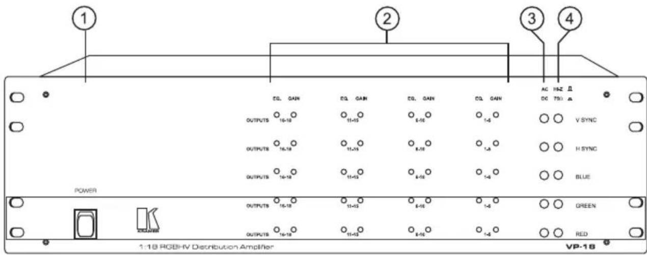

Figure 1: VP-10/15/18 Front/Rear Panel Features
Table 1: VP-10/15/18 Front/Rear Panel Features
| No. | Feature Function | |
| 1 | Power Switch | Illuminated switch: Supplies power to the unit. |
| 2 | Gain/EQ. Control trimmers | Adjust output levels and cable EQ. |
| 3 | AC/DC selection switches | Input coupling selection switches. |
| 4 | Hi-Z/75 Ω selection switches | Termination switches for the inputs. |
| 5 | INPUT BNCs | RGBHV input connectors |
| 6 | LOOP BNCs | Loop connectors for DA extension |
| 7 | OUTPUT BNCs | RGBHV output connectors |
| 8 | POWER connector | A 3-prong AC connector allows power to be supplied to the unit. Directly underneath this connector, a fuse holder houses the appropriate fuse. |
5 INSTALLATION
5.1 Rack Mounting
Each of the amplifiers included in this manual may be rack mounted in a standard 19" (3U) EIA rack assembly, and includes rack "ears" at the ends of the front panel. These devices do not require any specific spacing above or below the unit for ventilation. To mount any of the amplifiers, simply place the unit rack ears against the rack rails of your rack, and fasten with standard screws through each of the four corner holes in the rack ears. It is recommended to use plastic washers to protect the panel from scratching.
5.2 Connecting to RGBHV Devices
RGBHV video sources and output devices (such as monitors, projectors, etc.) may be connected to the amplifiers through the BNC type connectors located on the back of the units. Unused inputs are terminated to 75ohm, and active inputs should be terminated at the connecting source. Please keep in mind that the output signal format will match that of the input signal format. (Example: If input is composite, then output is composite.) All signal connections that use more than one cable interconnecting between devices should be of equal length. R, G, B cables between an RGBHV source and the amplifier should be equal in length and so should be the output cables.
6 USING the Amplifier
6.1 Typical Application
Computer based graphics is used in video production, in presentation applications, for education purposes and more. It is frequently necessary to distribute PC graphics from one source to several local and/or remote acceptors.
Perform the following steps:
- Preset the machine according to the description in section 6.2.
- Connect an RGBHV or VGA/XGA source (via a VGA to RGBHV cable or adapter) to the inputs of the amplifier, taking care to connect the RED output of the source to the RED input of the amplifier, GREEN to GREEN, etc. Use equal length cables for all signals.
- The looping function enables the operator to extend the number of outputs per input. The following example describes looping performed by using 3 amplifiers with one input and 18 outputs each: An RGBHV signal reaches inputs of amplifier No. 1. From the appropriate looping connectors of amplifier No. 1 a cable is connected to the appropriate input sockets of amplifier No. 2. The loop outputs of amplifier No. 2 are connected to the input sockets of amplifier No. 3. By this way the input signal is divided into 54 separate output signals. The operator must always switch the termination switches of all the amplifiers but the last to "Hi-z". The last amplifier's
termination switches should always be at "75Ohm" to maintain well-matched video line (of 75Ohm impedance) from first to last amplifier. Note that if looping function is not used, the termination switch should be set to "75 Ohm". Note: If TTL level Syncs (H\& V) are used, then all termination switches related to the Horizontal and Vertical inputs, including the last machine's switches should be in the Hi-z position.
- If looping is not used, connect an RGBHV monitor (if needed) to the loop connectors of the amplifier.
- Connect RGBHV acceptors to the outputs of the amplifier, taking care to connect the RED output of the amplifier to the RED input of the acceptor, GREEN to GREEN, etc. Use equal length cables for all signals.
- Operate the amplifier, source and acceptors.
- Adjust, if needed, the level control and the cable EQ. control. As described in section 6.3 - "handling signal losses".
6.2 VP-10/15/18 Preset
In order to use thVP-10/15/18 efficiently, the machine should be preset to the required application. The input coupling can be selected by the user to be either AC or DC. In general, if the source is of high quality and conforms to the standards, then DC coupling should be selected on all inputs by pressing in the relevant buttons (DC coupling). If however the source is a non-standard source, the signals may ride on DC offset voltages. In this case the AC/DC buttons should be released (AC coupling). If the amplifier is used for proper RGBHV signals (RGB are analog, H&V are TTL level) then the AC/DC switches should be used (if needed) only for the RGB signals. The H&V should always remain in the DC position (pressed-in).
The default state of those buttons should be at DC coupling (pressed-in). Only if there are problems (signals are too dark, too bright, looking "burned" or distorted) toggle the AC/DC switches, of the RGB channels only, into the AC position (released).
6.3 Handling signal losses
High-resolution RGBHV-VGA/XGA signals are very sensitive to cable length and quality. Long and/or low quality cables tend to degrade the signal quality, resulting in image "smear" and fine-detail loss, as well as signal level attenuation.
The VP-10/15/18 allow the user to handle and correct those problems, using the built-in amplifiers. Using high quality cables of 2-4 meter length will not require adjustment, even when the signals involved are UXGA signals (1600x1200 resolution).
Even with the best available cables at SXGA resolution (1280x1024) or UXGA resolution, there might be apparent signal depreciation at over five meters. In low quality cables, those high-resolution signals will be affected at distances even shorter
than one meter. The VP-10/15/18 have two sets of user adjustable controls, each set effecting 5 outputs simultaneously (besides the sets for outputs 16-18, effecting only three outputs) which should be used as following:
-
If you see a signal detail loss (resulting in image "smear" and blurring on the screen) carefully turn the EQ. control trimmers clockwise, until the lost details reappear and the original resolution is resumed. These control trimmers gradually compensate for the losses incurred within the cable due to its design or le All the relevant RGB channels should be tuned similarly, otherwise color aberrations might appear. Bear in mind though that beyond a certain distance, dictated by the cable stray-capacitance (a measure of cable quality) losses cannot be completely recovered. In this case, it is advised that a lower graphics resolution should be chosen or the cable should be replaced with a better one.
-
If the whole signal is attenuated, the image on the screen will become darker. In this case, carefully tune the LEVEL control trimmers clockwise. All the relevant RGB channels should be tuned similarly; otherwise image hue and brightness might be badly affected. Overdoing these controls will result in image "burnout" and might damage the signal receiver, therefore, adjusting these controls should be done very carefully. Between the EQ. controls (that should be adjusted first) and the LEVEL controls, much of the lost signals may be restored.
6.4 Other Uses
The VP-10/15/18 use almost identical 5 independent channels. The VP-18, for example, can be used as 5 independent 1:18 video distribution amplifiers, using the RED channel for one source, the GREEN channel for the other source and so on. The machine can be used, for example, as a 1:18 Video Component DA, using the RED, GREEN and BLUE channels for Y, R-Y, and B-Y, and at the same time as a 1:18 s-Video DA, using the H and V channels for Y and C. As the machine has 5 identical, very high bandwidth independent channels, they can be used for any demanding video distribution application, even for short range (up to 20 meters) SDI distribution.
7 SPECIFICATIONS
| INPUTS: | Analog Red, Green, Blue signals - 0.7 Vpp/75 Ω, H & V syncs, TTL or analog level on BNC connectors with termination switches and AC/DC input coupling selection switches. |
| OUTPUTS: | 10/15/18 sets of analog Red, Green, Blue signals - 0.7 Vpp/75 Ω, H & V syncs, TTL or analog level on BNC connectors with termination switches and AC/DC input coupling selection switches. |
| BANDWIDTH: | 360 MHz -3dB. |
| CROSSTALK | -65 dB. |
| VIDEO S/N RATIO: | 71 dB. |
| DIFF. GAIN: | 0.12%. |
| DIFF. PHASE: | 0.15 Deg. |
| K-FACTOR: | <0.05% |
| CONTROLS: | Output Level (-1.4 to + 1.7 dB), EQ. (0 to 2.3 dB @ 5 MHz) for sets of 5 outputs. |
| DIMENSIONS: | 19-inch (W), 7-inch (D) 3U (H) rack mountable. |
| POWER SOURCE: | 230 VAC, 50/60 Hz, (115 VAC, U.S.A.) 7 VA max. |
| WEIGHT: | 6 kg. (13.2 lbs.) Approx. |
| ACCESSORIES: | Power cord. |
8 TROUBLESHOOTING
NOTES
-
Please note that if the output signal is disturbed or interrupted by very strong external electromagnetic interference, it should return and stabilize when such interference ends. If not, disconnect power from the machine and reconnect again to reset the machine.
-
If the recommended actions still do not result in satisfactory operation, please consult your KRAMER Dealer.
8.1 Power and Indicators
| Problem Remedy | |
| No Power | 1. Confirm that rocker switch is in “ON” position, and lamp within the switch is illuminated. 2. Confirm that power connections are secured at the amplifier and at the receptacle. Make sure the receptacle is active, outputting the proper mains voltage. 3. If there is still no power, check the fuse. Remove power cord from the AC outlet and from the machine and then, using a flat head screwdriver, remove the fuse holder located directly below the power connector. Confirm that the fuse is good by looking at the wire connected to the ends of the fuse. If the wire is broken, replace the fuse with another, with the same value. |
8.2 RGBHV Signal
| Problem Remedy | |
| No signal at the output device, regardless of input selected. | 1. Confirm that your sources and output devices are powered on and connected properly. Video signals at the input and output of your amplifier should be of identical signal format at the output of your source. 2. Confirm that any other amplifiers in the signal path have the proper input and/or output selected. |
| Signal level is too high or too dim. | 1. Verify that the lines are well matched through 75Ohm impedances; otherwise it results in a video level that is too high or too dim. 2. Confirm that the connecting cables are of high quality and properly inserted. 3. Check level controls on your source input device output display. |
| Noise bars "roll" up or down in the output image or: Low Frequency Hum in the output signal | 1. Hum bars (ground loop) are caused by a difference in the ground potential of any two or more devices connected to your signal path. This difference is compensated by passing that voltage difference through any available interconnection, including your cables. WARNING! Do not disconnect the ground from any piece of equipment in the signal path! 2. Check the following to remove hum bars: 3. Confirm that all interconnected equipment is connected to the same power phase, if possible. 4. Remove equipment connected to that phase that may introduce noise, such as motors, generators, etc. 5. Disconnect all interconnecting cables and reconnect them one at a time until the ground loop reappears. Disconnect the affected cable and replace, or insert an isolation transformer in the signal path. |
LIMITED WARRANTY
Kramer Electronics (hereafter Kramer) warrants this product free from defects in material and workmanship under the following terms.
HOW LONG IS THE WARRANTY
Labor and parts are warranted for three years from the date of the first customer purchase.
WHO IS PROTECTED
Only the first purchase customer may enforce this warranty.
WHAT IS COVERED AND WHAT IS NOT COVERED
Except as below, this warranty covers all defects in material or workmanship in this product. The following are not covered by the warranty:
1) Any product which is not distributed by Kramer, or which is not purchased from an authorized Kramer dealer. If you are uncertain as to whether a dealer is authorized, please contact Kramer at one of the agents listed in the web site www.kramerelectronics.com.
2) Any product, on which the serial number has been defaced, modified or removed.
3) Damage, deterioration or malfunction resulting from:
a) Accident, misuse, abuse, neglect, fire, water, lightning or other acts of nature.
b) Product modification, or failure to follow instructions supplied with the product.
c) Repair or attempted repair by anyone not authorized by Kramer.
d) Any shipment of the product (claims must be presented to the carrier).
e) Removal or installation of the product.
f) Any other cause, which does not relate to a product defect.
g) Cartons, equipment enclosures, cables or accessories used in conjunction with the product.
WHAT WE WILL PAY FOR AND WHAT WE WILL NOT PAY FOR
We will pay labor and material expenses for covered items. We will not pay for the following:
1) Removal or installations charges.
2) Costs of initial technical adjustments (set-up), including adjustment of user controls or programming. These costs are the responsibility of the Kramer dealer from whom the product was purchased.
3) Shipping charges.
HOW YOU CAN GET WARRANTY SERVICE
1) To obtain service on you product, you must take or ship it prepaid to any authorized Kramer service center.
2) Whenever warranty service is required, the original dated invoice (or a copy) must be presented as proof of warranty coverage, and should be included in any
shipment of the product. Please also include in any mailing a contact name, company, address, and a description of the problem(s).
3) For the name of the nearest Kramer authorized service center, consult your authorized dealer.
LIMITATION OF IMPLIED WARRANTYES
All implied warranties, including warranties of merchantability and fitness for a particular purpose, are limited in duration to the length of this warranty.
EXCLUSION OF DAMAGES
Kramer's liability for any defective products is limited to the repair or replacement of the product at our option. Kramer shall not be liable for:
1) Damage to other property caused by defects in this product, damages based upon inconvenience, loss of use of the product, loss of time, commercial loss; or:
2) Any other damages, whether incidental, consequential or otherwise. Some countries may not allow limitations on how long an implied warranty lasts and/or do not allow the exclusion or limitation of incidental or consequential damages, so the above limitations and exclusions may not apply to you.
This warranty gives you specific legal rights, and you may also have other rights, which vary from place to place.
NOTE: All products returned to Kramer for service must have prior approval. This may be obtained from your dealer.
NOTICE
This equipment has been tested to determine compliance with the requirements of:
EN-50081: "Electromagnetic compatibility (EMC);
generic emission standard.
Part 1: Residential, commercial and light industry"
EN-50082: "Electromagnetic compatibility (EMC) generic immunity standard.
Part 1: Residential, commercial and light industry environment".
CFR-47 FCC Rules and Regulations:
Part 15- "Radio frequency devices:
Subpart B- Unintentional radiators
CAUTION!
Servicing the machines can only be done by an authorized Kramer technician. Any user who makes changes or modifications to the unit without the expressed approval of the manufacturer will void user authority to operate the equipment.
Use the supplied DC power supply to feed power to the machine.
Please use recommended interconnection cables to connect the machine to other components.

KRAMER
The list of Kramer distributors appears on our web site:
www.kramerelectronics.com
From the web site it is also possible to e-mail factory headquarters.
We welcome your questions, comments and feedback.
- Kramer Electronics, Ltd.
- USER MANUAL
- RGBHV Distribution Amplifiers
- Table Of Contents
- Section Name Page
- List Of Illustrations
- Figure Description
- List Of Tables
- Table Description
- INTRODUCTION
- A Word on VGA/XGA/RGBHV Distribution / Line Amplifiers
- Handling Graphics Signals
- Factors Affecting Quality of Results
- HOW DO I GET STARTED?
- UNPACKING AND CONTENTS
- Optional Accessories
- RGBHV DISTRIBUTION AMPLIFER
- Getting to Know Your VP-10/15/18 Distribution Amplifier
- INSTALLATION
- Rack Mounting
- Connecting to RGBHV Devices
- USING the Amplifier
- Typical Application
- VP-10/15/18 Preset
- Handling signal losses
- Other Uses
- SPECIFICATIONS
- TROUBLESHOOTING
- NOTES
- Power and Indicators
- RGBHV Signal
- LIMITED WARRANTY
- HOW LONG IS THE WARRANTY
- WHO IS PROTECTED
- WHAT IS COVERED AND WHAT IS NOT COVERED
- WHAT WE WILL PAY FOR AND WHAT WE WILL NOT PAY FOR
- HOW YOU CAN GET WARRANTY SERVICE
- LIMITATION OF IMPLIED WARRANTYES
- EXCLUSION OF DAMAGES
- NOTICE
- CAUTION!
Marque : Kramer
Modèle : VP18
Catégorie : Recepteur