
GTBUHDHBT2 - Extension audio/video Gefen - Notice d'utilisation et mode d'emploi gratuit
Retrouvez gratuitement la notice de l'appareil GTBUHDHBT2 Gefen au format PDF.
| Caractéristiques | Détails |
|---|---|
| Type de produit | Extension audio/vidéo |
| Résolution maximale supportée | 4K UHD (3840 x 2160) |
| Distance de transmission | Jusqu'à 100 mètres via câble CAT5e/6 |
| Connectivité vidéo | HDMI |
| Connectivité audio | Supporte le son multicanal jusqu'à 7.1 |
| Alimentation | Alimentation externe requise |
| Utilisation | Idéal pour les installations AV professionnelles et domestiques |
| Maintenance | Vérifier régulièrement les connexions et le bon fonctionnement des câbles |
| Sécurité | Ne pas exposer à l'humidité et éviter les chocs physiques |
| Informations générales | Compatible avec les appareils HDMI, facile à installer |
FOIRE AUX QUESTIONS - GTBUHDHBT2 Gefen
Questions des utilisateurs sur GTBUHDHBT2 Gefen
0 question sur cet appareil. Repondez a celles que vous connaissez ou posez la votre.
Poser une nouvelle question sur cet appareil
Téléchargez la notice de votre Extension audio/video au format PDF gratuitement ! Retrouvez votre notice GTBUHDHBT2 - Gefen et reprennez votre appareil électronique en main. Sur cette page sont publiés tous les documents nécessaires à l'utilisation de votre appareil GTBUHDHBT2 de la marque Gefen.
MODE D'EMPLOI GTBUHDHBT2 Gefen
4K ULTRA(HD)
HDBaseT™ Extender
w/ RS-232, 2-way IR, and POH
GBT-UHD-HBT2
User Manual
- Read these instructions.
- Keep these instructions.
- Heed all warnings.
- Follow all instructions.
- Do not use this product near water.
- Clean only with a dry cloth.
- Do not block any ventilation openings. Install in accordance with the manufacturer's instructions.
- Do not install or place this product near any heat sources such as radiators, heat registers, stoves, or other apparatus (including amplifiers) that produce heat.
- Do not defeat the safety purpose of the polarized or grounding-type plug. A polarized plug has two blades with one wider than the other. A grounding type plug has two blades and a third grounding prong. The wide blade or the third prong are provided for your safety. If the provided plug does not fit into your outlet, consult an electrician for replacement of the obsolete outlet.
- Protect the power cord from being walked on or pinched particularly at plugs, convenience receptacles, and the point where they exit from the apparatus.
- Only use attachments/accessories specified by the manufacturer.
- To reduce the risk of electric shock and/or damage to this product, never handle or touch this unit or power cord if your hands are wet or damp. Do not expose this product to rain or moisture.
- Unplug this apparatus during lightning storms or when unused for long periods of time.
- Refer all servicing to qualified service personnel. Servicing is required when the apparatus has been damaged in any way, such as power-supply cord or plug is damaged, liquid has been spilled or objects have fallen into the apparatus, the apparatus has been exposed to rain or moisture, does not operate normally, or has been dropped.
- Batteries that may be included with this product and/or accessories should never be exposed to open flame or excessive heat. Always dispose of used batteries according to the instructions.
Gefen warrants the equipment it manufactures to be free from defects in material and workmanship.
If equipment fails because of such defects and Gefen is notified within two (2) years from the date of shipment, Gefen will, at its option, repair or replace the equipment, provided that the equipment has not been subjected to mechanical, electrical, or other abuse or modifications. Equipment that fails under conditions other than those covered will be repaired at the current price of parts and labor in effect at the time of repair. Such repairs are warranted for ninety (90) days from the day of reshipment to the Buyer.
This warranty is in lieu of all other warranties expressed or implied, including without limitation, any implied warranty or merchantability or fitness for any particular purpose, all of which are expressly disclaimed.
- Proof of sale may be required in order to claim warranty.
- Customers outside the US are responsible for shipping charges to and from Gefen.
- Copper cables are limited to a 30 day warranty and cables must be in their original condition.
The information in this manual has been carefully checked and is believed to be accurate. However, Gefen assumes no responsibility for any inaccuracies that may be contained in this manual. In no event will Gefen be liable for direct, indirect, special, incidental, or consequential damages resulting from any defect or omission in this manual, even if advised of the possibility of such damages. The technical information contained herein regarding the features and specifications is subject to change without notice.
For the latest warranty coverage information, refer to the Warranty and Return Policy under the Support section of the Gefen Web site at www.gifen.com.
Technical Support
(707) 283-5900 (800) 472-5555
8:00 AM to 5:00 PM Monday - Friday, Pacific Time
support@gefen.com
Web
http://www.gefen.com
Mailing Address
Gefen
Core Brands, LLC
c/o Customer Service
1800 S McDowell Blvd
Petaluma, CA 94954
Product Registration
Register your product here: http://www.gefen.com/kvm/Registry/Registration.jsp
- The Gefen Syner-G Software Suite is a free downloadable application from Gefen that provides automatic download and installation of firmware upgrades as well as EDID management.
Download the application here: http://www.gefen.com/synerg
4K Ultra HD HDBase™ Extender w/ RS-232, 2-way IR, and POH is a trademark of Gefen, LLC.
© 2016 Gefen, LLC. All Rights Reserved. All trademarks are the property of their respective owners.
Gefen, LLC reserves the right to make changes in the hardware, packaging, and any accompanying documentation without prior written notice.


This product uses UL listed or CE-compliant power supplies.
Features
- Extends HDMI, RS-232, and 2-way IR over a single CAT-5e
▶ 4K Ultra HD (3840 x 2160 @ 60Hz, 4:2:0, 8-bit), up to 330 feet/100 meters
▶ 4K Ultra HD (3840 x 2160 @ 30Hz, 4:4:4, 8-bit), up to 330 feet/100 meters
4K DCI-Cinema (4096 x 2160 @ 30Hz 4:4:4, 8-bit), up to 330 feet/100 meters
1080p Full HD (1920 x 1080 @ 60Hz, 4:4:4, 12-bit), up to 330 feet/100 meters
▶ 1080p Full HD (1920 x 1080 @ 60Hz, 4:4:4, 8-bit), up to 495 feet/150 meters
WUXGA (1920 x 1200 @ 60Hz, 8-bit), up to 495 feet/150 meters
- HDMI Features Supported:
HDMI 2.0 up to 4K 60Hz, 4:2:0, 8-bit color
HDCP 2.2 and 1.4
12-bit Deep Color
LPCM 7.1 audio, Dolby Atmos®, Dolby® TrueHD, DTS:X™, and DTS-HD Master Audio™ pass-through
3DTV pass-through
CEC pass-through
Lip Sync pass-through
- IR extension from Sender to Receiver and from Receiver to Sender
- POH (Power Over HDBaseT™) feature provides power to the Receiver unit over the link cable - only the Sender unit needs external power
- Advanced EDID Management via Gefen Syner-G™ software
- Link Quality Monitoring via Gefen Syner-G™ software
- In-field firmware update via USB, using Gefen Syner-G™ software
- Locking power connector
- Low profile, surface-mountable enclosures
4K ULTRA 60Hz, 4:2:0


HDCP2.2
HOMI2.0


Packing List
The 4K Ultra HD HDBaseT Extender w/ RS-232, 2-way IR, and POH ships with the items listed below. The packing contents of the Sender and Receiver unit are listed below. If any of these items are not present in the box when you first open it, immediately contact your dealer or Gefen.
- 1 x 4K Ultra HD HDBaseT™ Extender w/ RS-232, 2-way IR, and POH (Sender)
- 1 x 4K Ultra HD HDBaseT™ Extender w/ RS-232, 2-way IR, and POH (Receiver)
- 1 x IR emitter
- 1 x IR extender
- 1 x DB-9 cable (M-F)
- 1 x 48V DC locking power supply
1 x Quick-Start Guide
Table of Contents
1 Getting Started
Introduction. 2
Sender Unit 2
Receiver Unit 4
Installation 6
Connection Instructions 6
Application Diagram 7
2 Basic Operation
DIP Switch Configuration 10
Sender unit 10
Receiver unit 13
Notes on IR Carrier Signals 14
LED Status 15
Bidirectional IR Control. 16
Controlling the Source from the Viewing Location 16
Controlling the Display from the Source Location 17
Controlling the Source / Display from Different Locations 18
RS-232 Interface 19
RS-232 Interface 19
3 Advanced Operation
Using Syner-GTM 24
Verifying the USB Driver 24
Downloading an EDID 26
Uploading an EDID 29
Copying an EDID 31
Viewing an EDID 33
Link Quality Monitoring 37
4 Appendix
Updating the Firmware 46
Default Settings 52
Sender Unit DIP Switches 52
Receiver Unit DIP Switches 52
Network Cable Diagram 53
Specifications 54
Index. 55
This page left intentionally blank.
This page left intentionally blank.

HDBaseT™ Extender
w/ RS-232, 2-way IR, and POH
1 Getting Started
Sender Unit

| ID Name Description | ||
| 1 | DIP switches | See DIP Switch Configuration (page 10) for more information. |
| 2 USB For use with the Syner-G Software Suite. | See Using Syner-GTM (page 24) for more information. | |
| 3 Link (LED) This LED indicator glows solid green when the Sender and Receiver unit are connected by a CAT-5 (or better) cable. | ||
| 4 Power This LED indicator glows solid blue when the Sender unit is powered. | ||
| 5 Video This LED indicator glows solid amber when HDCP content is detected. If Non-HDCP content is detected, then this LED indicator will flash amber. | ||
| 6 POH 48V DC Connect the included 48V DC power supply to this connector. | ||
| 7 RS-232 Connect the included RS-232 cable from this port to an automation device. See RS-232 Interface (page 19) for more information. | ||
| 8 IR In / Ext Connect an IR extender (Gefen part no.EXT-RMT-EXTIRN) to this port. | ||
| 9 IR Out Connect an IR emitter (Gefen part no.EXT-2IREMIT) to this port. | ||
| 10 Link | Connect a CAT-5 (or better) cable from this port to the Link port on the Receiver unit. | |
| 11 | HDMI In | Connect a 4K Ultra HD source to this HDMI port using an HDMI cable. |
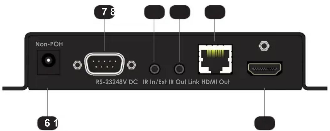
Receiver Unit
| ID Name Description | ||
| 1 | DIP switches | See DIP Switch Configuration (page 10) for more information. |
| 2 USB For use with the Syner-G Software Suite. | See Using Syner-GTM (page 24) for more information. | |
| 3 Link (LED) This LED indicator glows solid green when the Sender and Receiver unit are connected by a CAT-5 (or better) cable. | ||
| 4 Power This LED indicator glows solid blue when the Sender unit is powered. | ||
| 5 Video This LED indicator glows solid amber when HDCP content is detected. If Non-HDCP content is detected, then this LED indicator will flash amber. | ||
| 6 Non-POH 48V DC Use this port only when using a HDBaseT-compatible device as the Sender. | ||
| 7 RS-232 Connect the included RS-232 cable from this port to an automation device. See RS-232 Interface (page 19) for more information. | ||
| 8 IR In / Ext Connect an IR extender (Gefen part no.EXT-RMT-EXTIRN) to this port. | ||
| 9 IR Out Connect an IR emitter (Gefen part no.EXT-IREMIT) to this port. | ||
| 10 Link Connect a CAT-5 (or better) cable from this port to the Link port on the Receiver unit. | ||
| 11 | HDMI In | Connect a 4K Ultra HD source to this HDMI port using an HDMI cable. |
Connection Instructions
Video
- Connect the included HDMI cable from the 4K Ultra HD source to the HDMI In port on the Sender unit.
- Connect an HDMI cable from the HDMI Out port on the Receiver unit to the 4K Ultra HD display.
▶ Link
- Connect a shielded CAT-5e (or better) cable from the Link port on the Sender unit to the Link port on the Receiver unit.
| Maximum Resolution Mode Distance | ||
| 1920 x 1080p 60 Hz @ 8-bit Long Reach mode 495 feet (150 meters) | ||
| 3840 x 2160p 60 Hz @ 4:2:0 Normal mode 330 feet (100 meters) |
See DIP Switch Configuration (page 10) for more information on setting the extension distance.
IR Control - see Bidirectional IR Control (page 16) for more information
4. Connect the included IR emitter to the IR Out port on the Sender unit.
5. Connect the included IR extender to the IR In/Ext port on the Receiver unit.
RS-232 - see RS-232 Interface (page 19) for more information
- Connect the included DB-9 cable from the automation device to the RS-232 port on the Sender unit
- Connect a DB-9 cable from the RS-232 port on the Receiver unit to the RS-232 device to be controlled.
Power
- Connect the included power supply to the POH 48V DC connector on the Sender unit.
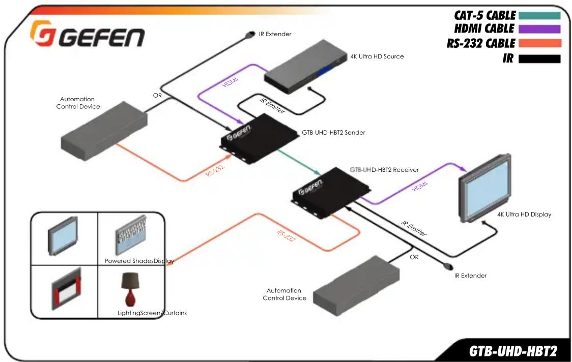
Application Diagram
This page left intentionally blank.

HDBaseT™ Extender
w/ RS-232, 2-way IR, and POH
2 Basic Operation
Sender unit
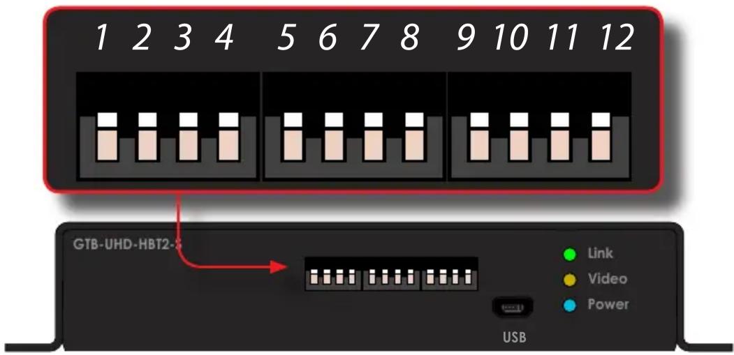
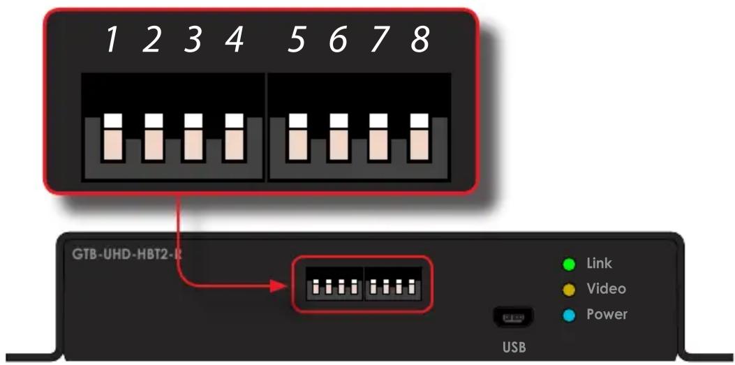
The back panel of the Sender unit contains three banks of DIP switches. Each bank contains four DIP switches. These DIP switches control EDID, HPD, HDCP, IR, and HDBT mode. The default setting, for each DIP switch, is in the "down" (OFF) position.
Each DIP switch (1 - 12) is arranged from left to right. DIP switches 11 and 12 are not used. Although the DIP switch numbers do not appear on the unit, we have included them for easy reference.
If a DIP switch is in the "up" position, then it is ON. If a DIP switch is in the "down" position, then it is OFF.
DIP Feature Description
| 1 | Local / pass-through EDID | ON Allows all video and audio features of the connected device to be passed to the source device. OFF (default) Copies the downstream EDID locally in HDBT mode; modifies downstream EDID to support only up to 1080p60 8-bit in Long Reach mode. |
| 2 | Hot-Plug Detect | ON HPD pass-through. HPD will toggle, depending on the HPD status of the display (sink) or source device. OFF (default) HPD is always high, even when the display is hot-plugged (disconnected from then reconnected to the source device). |
DIP Feature Description
| 3 | EDID Lock | ON EDID Lock enabled. The current EDID will be stored on the input even if the unit is power-cycled. OFF (default) EDID Lock disabled. |
| 4 | HDCP Control | ON Prevents HDCP content from passing through to the display (sink) device. OFF (default) Allows HDCP content to pass through to the display (sink) device. |
| 5 | Sender unit IR carrier | ON IR carrier signal is stripped at the Sender unit. OFF (default) IR carrier signal is passed-through. |
| 6 | Receiver unit IR carrier | ON IR carrier signal is stripped at the Receiver unit. OFF (default) IR carrier signal is passed-through. |
| 7 IR Polarity ▷ ON | Set to work with third-party IR extenders. OFF (default) Operates with Gefen part no. EXT-RMT-EXTIRN. | |
| 8 | Long-Reach Mode | ON Resolutions up to 1080p 60 Hz can be extended to a maximum distance of 495 feet (150 meters). Color depth is limited to 8-bit. OFF (default) HDBT mode. Resolutions up to 3840 x 2160p 60 Hz @ 4:2:0, can be extended up to 330 feet (100 meters). |
DIP Feature Description
| 9 | IR Carrier Frequency | ON 56 kHz. OFF (default) 38 kHz. |
| 10 | IR Carrier Frequency | ON 47 kHz. OFF (default) Depends upon setting of DIP 9. |
| 11 N/A -- | ||
| 12 N/A -- | ||
Receiver unit
The back panel of the Receiver unit contains three banks of DIP switches. Each bank contains four DIP switches. The default setting, for each DIP switch, is in the "down" (OFF) position.
Each DIP switch (1 - 12) is arranged from left to right. DIP switch 7 and 8 are not used. Although the DIP switch numbers do not appear on the unit, we have included them for easy reference.
If a DIP switch is in the "up" position, then it is ON. If a DIP switch is in the "down" position, then it is OFF.
DIP Feature Description
| 1 IR Carrier Frequency ▷ ON | IR carrier signal is stripped at the Sender unit. ▷ OFF (default) IR carrier signal is passed-through. | |
| 2 IR Carrier Frequency ▷ ON | IR carrier signal is stripped at the Receiver unit. ▷ OFF (default) IR carrier signal is passed-through. | |
| 3 | IR Polarity | ▷ ON Set to work with third-party IR extenders. ▷ OFF (default) Operates with Gefen part no. EXT-RMT-EXTIRN. |
DIP Feature Description
| 4 | Long-Reach Mode | ON Resolutions up to 1080p Full HD can be extended to a maximum distance of 495 feet (150 meters). Color depth is limited to 8-bit. OFF (default) HDBT mode. Resolutions up to 4K x 2K, can be extended up to 330 feet (100 meters) with deep color (4:2:0). |
| 5 | IR Carrier Frequency | ON 56 kHz. OFF (default) 38 kHz. |
| 6 | IR Carrier Frequency | ON 47 kHz. OFF (default) Depends upon setting of DIP 5. |
| 7 N/A | -- | |
| 8 N/A | -- |
Notes on IR Carrier Signals
When an IR carrier frequency is passed through from the Sender unit to the Receiver unit, or from the Receiver unit to the Sender unit, the carrier signal is not renewed. Any carrier frequency between 30kHz and 60kHz is natively passed through.
If the IR carrier signal is stripped at the Sender unit and added at the Receiver unit (or vice versa), then the carrier signal can be set to 38kHz , 47kHz , or 56kHz .
To set the carrier signal frequency on the Sender unit, set DIP switch 5 on the Sender unit to the OFF position and use DIP switches 9 and 10 (Sender) to set the carrier frequency. To set the carrier signal frequency on the Receiver unit, set DIP switch 1 on the Receiver unit to the OFF position and use DIP switches 5 and 6 (Receiver) to set the carrier frequency.
Stripping the IR carrier signal is commonly used when directly connecting an IR cable from the output of one device to the input on another IR device.
The Link, Video, and Power LED indicators provide basic information on the current status of the this product.
The information, in the table below, applies to both the Sender and Receiver unit.
| LED Status Description | ||
| Link | Solid green | The Sender / Receiver unit is powered. Link integrity between Sender and Receiver unit is good. |
| Video | Solid amber Flashing amber | HDCP content is detected Non-HDCP content is detected. |
| Power | Solid blue | The Sender / Receiver unit is powered. |
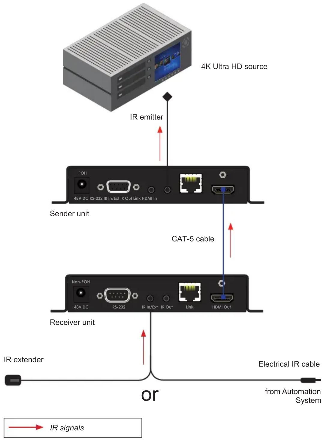
Controlling the Source from the Viewing Location
- Connect an IR extender (Gefen part no. EXT-RMT-EXTIRN) to the IR In/Ext port on the Receiver unit. If using an automation system, connect the 3.5mm mini-mono connector from the IR In/Ext port on the Receiver unit to the automation system. IR signals are transmitted over the CAT-5 cable.
- Connect the IR emitter from the IR Out port, on the Sender unit, to the IR sensor window on the source device.
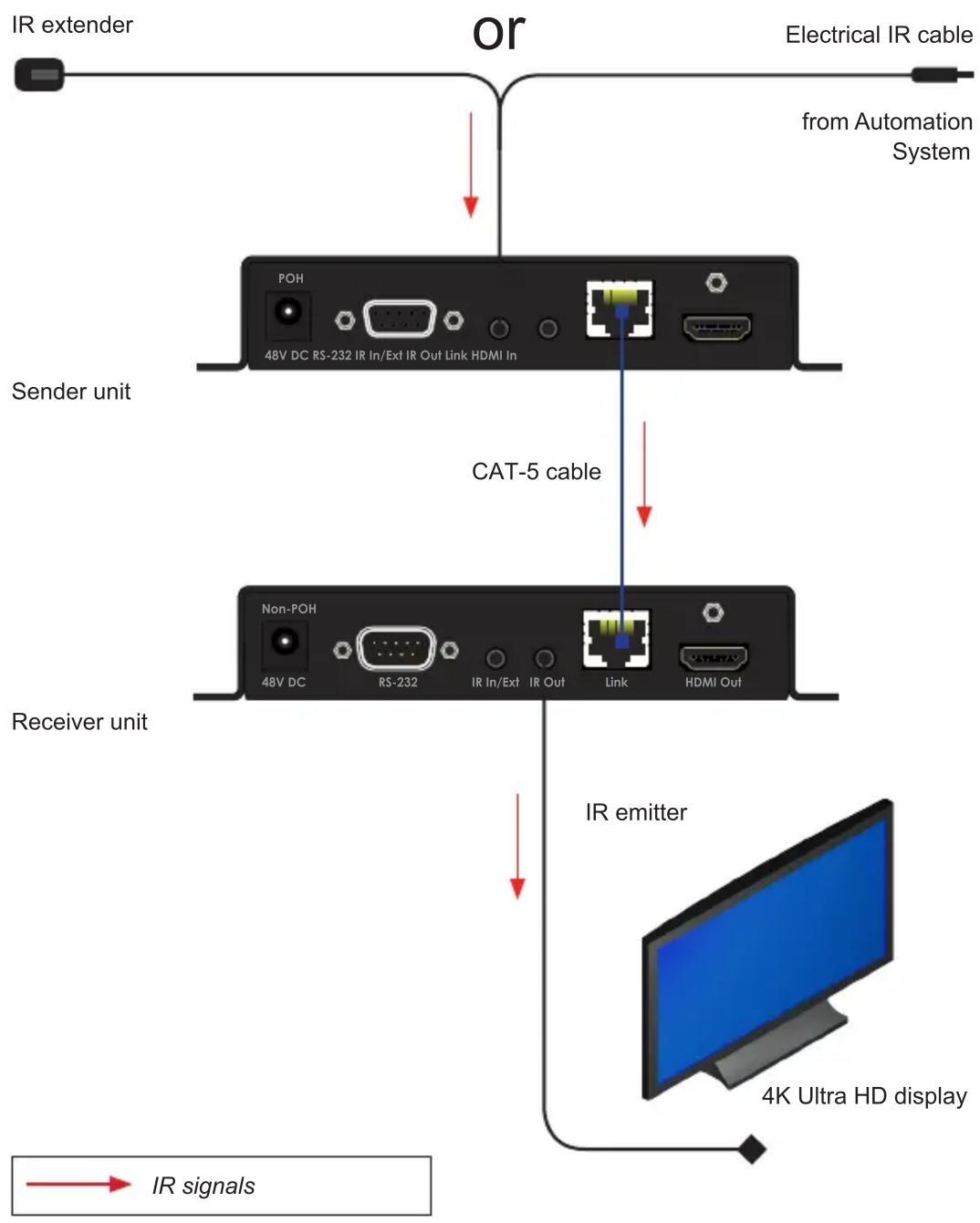
Controlling the Display from the Source Location
- Connect an IR extender (Gefen part no. EXT-RMT-EXTIRN) to the IR In/Ext port on the Sender unit. If using an automation system, connect the 3.5mm mini-mono connector from the IR In/Ext port on the Receiver unit to the automation system. IR signals are transmitted over the CAT-5 cable.
- Connect an IR emitter (Gefen part no. EXT-IREMIT) from the IR Out port on the Receiver unit to the IR sensor on the display.
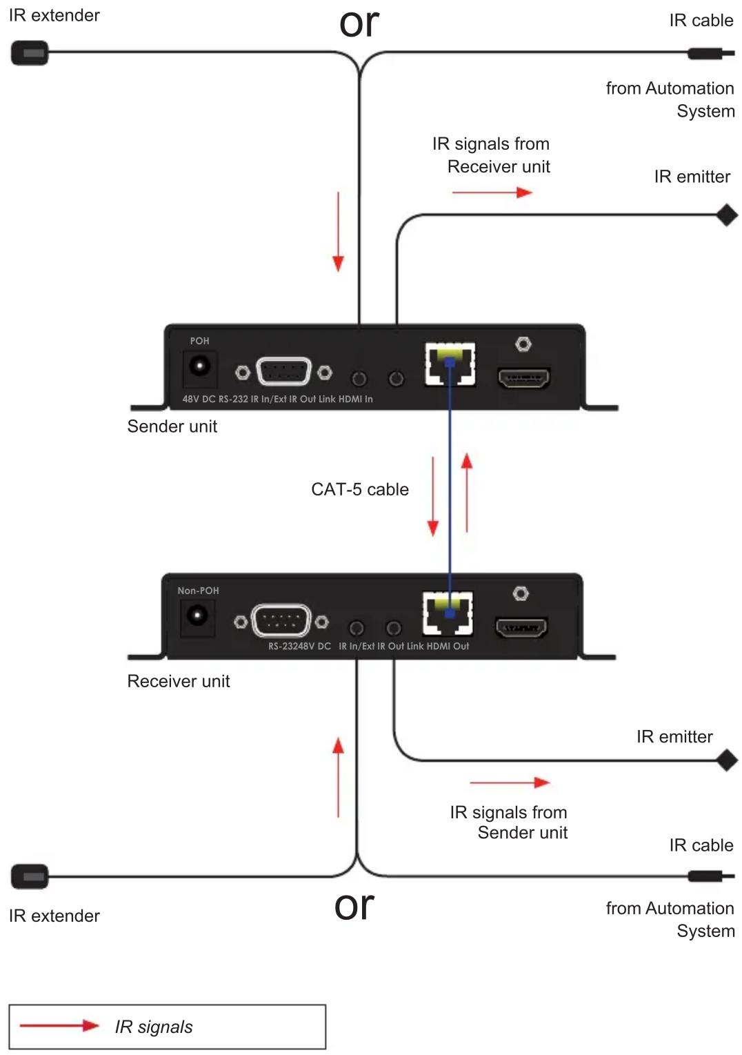
Controlling the Source / Display from Different Locations
Bidirectional IR allows the source and/or display to be controlled from the Sender or Receiver unit. Refer to the diagram, below, for connection details. IR signals are transmitted over the CAT-5 cable.
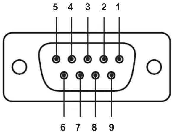
RS-232 Interface
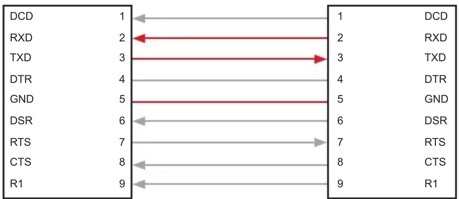
Automation Device Extender
Only TXD, RXD, and GND pins are used.
This product supports RS-232 pass-through, allowing the control of remote RS-232 devices.
In the example below, an RS-232 device has been connected to the Receiver unit. Connect the automation control device to the Sender unit.
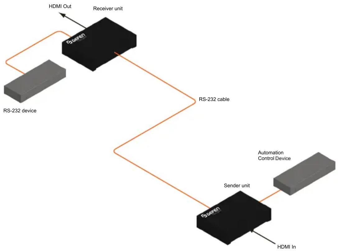
Figure 2.1 - Basic RS-232 connection
This page left intentionally blank.
This page left intentionally blank.

HDBaseT™ Extender
w/ RS-232, 2-way IR, and POH
3 Advanced Operation
Verifying the USB Driver
In order to use this product with the Gefen Syner-G™ software, a USB driver must be installed on the computer that is running the Syner-G™ software. This driver is automatically installed when the Syner-G™ Software Suite is installed.
- Download and install the Gefen Syner-G™ Software Suite. The Syner-G™ software can be downloaded here: http://www.gefen.com/synerg
- Connect a mini-USB-to-USB cable (not included) from the USB port on the front of the Sender or Receiver unit to an available USB port on the computer.
- From the Windows Desktop, click the Start button, select Computer, then right-click and select Manage from the context menu.
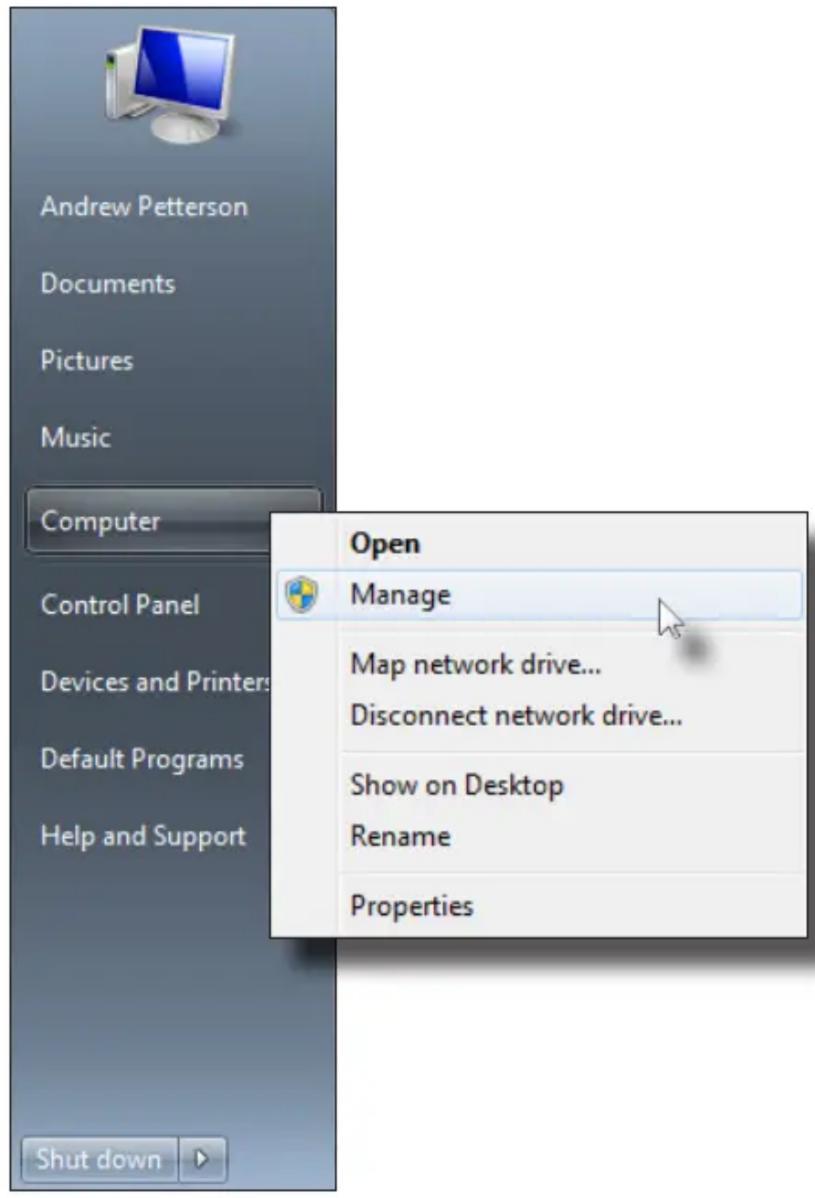
- The Computer Management window will open.
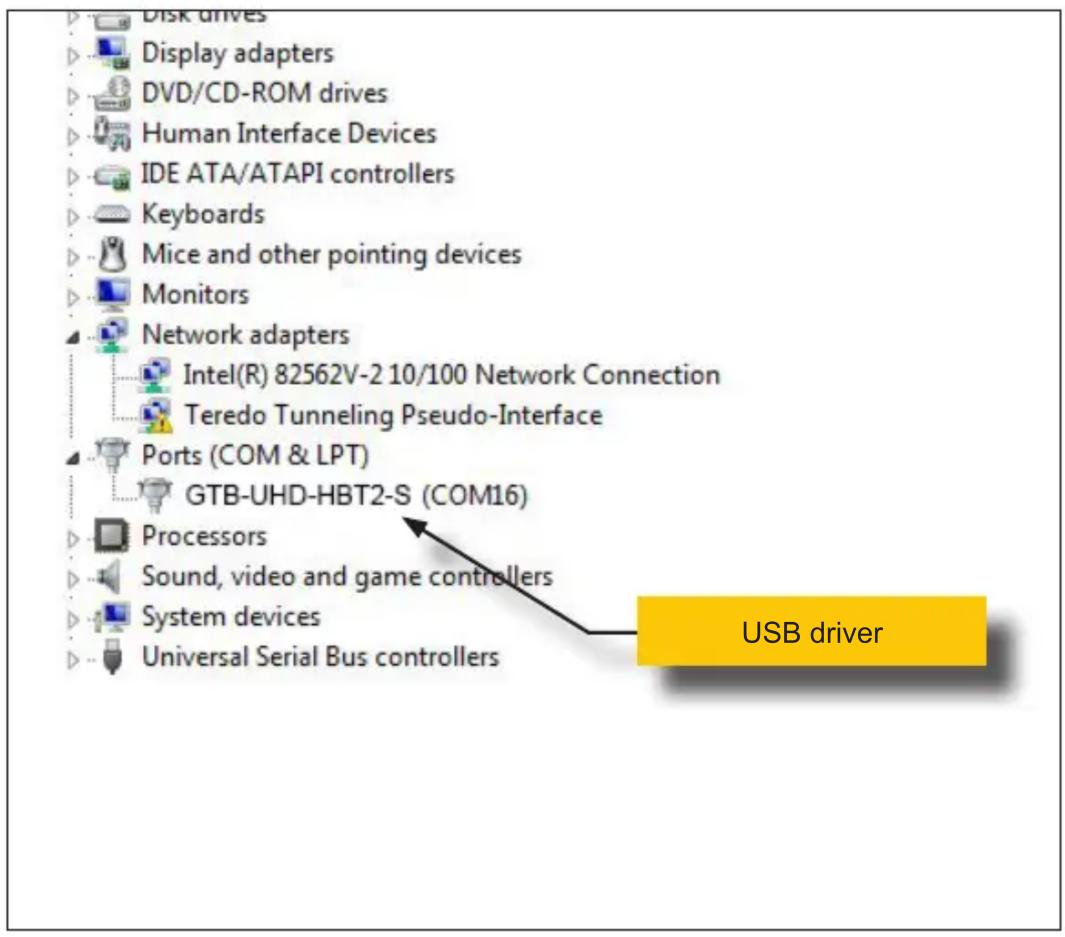
- In the left window pane, under System Tools, click Device Manager.
- In the right window pane, locate Ports (COM & LPT).
The device driver will be displayed. In this case, GTB-UHD-HBT2-S will be displayed. If the USB cable is connected to the Receiver unit, then the device driver will be GTB-UHD-HBT2-R.
Downloading an EDID
EDID data can be downloaded from the connected Gefen Detective device to a local file. Note that the Downstream EDID or Bank EDID data cannot be downloaded to a file. To download this EDID data, it must first be copied to the Local EDID. See Copying an EDID (page 31) for more information on copying EDID data.
- Click the Manage a Product button and select the connected product from the drop-down list.
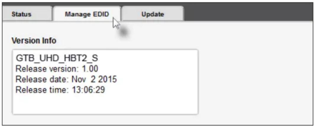
- Click the Manage EDID tab.
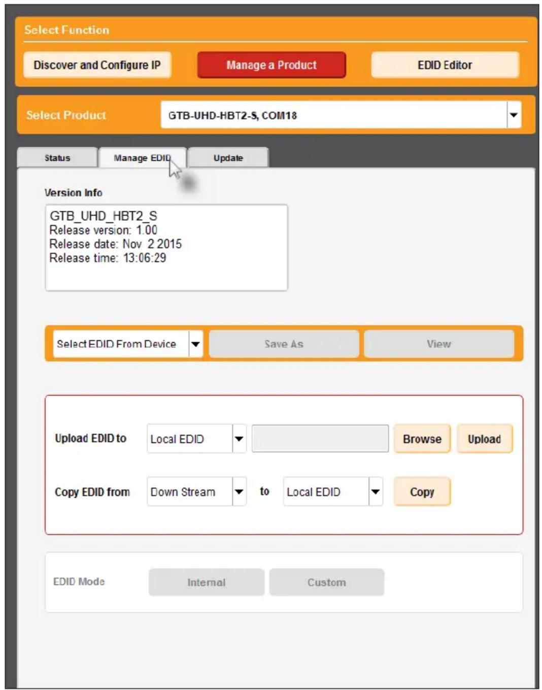
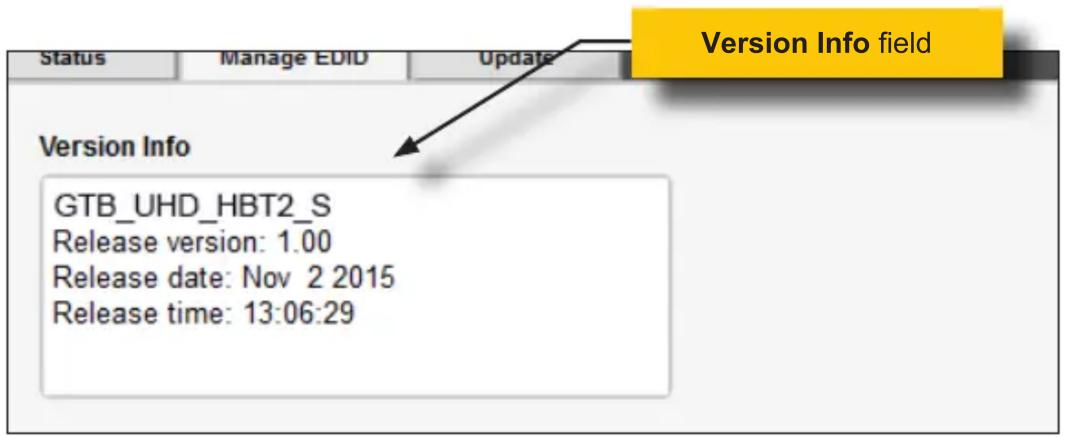
- Information about the currently selected device will be displayed in the Version Info field.
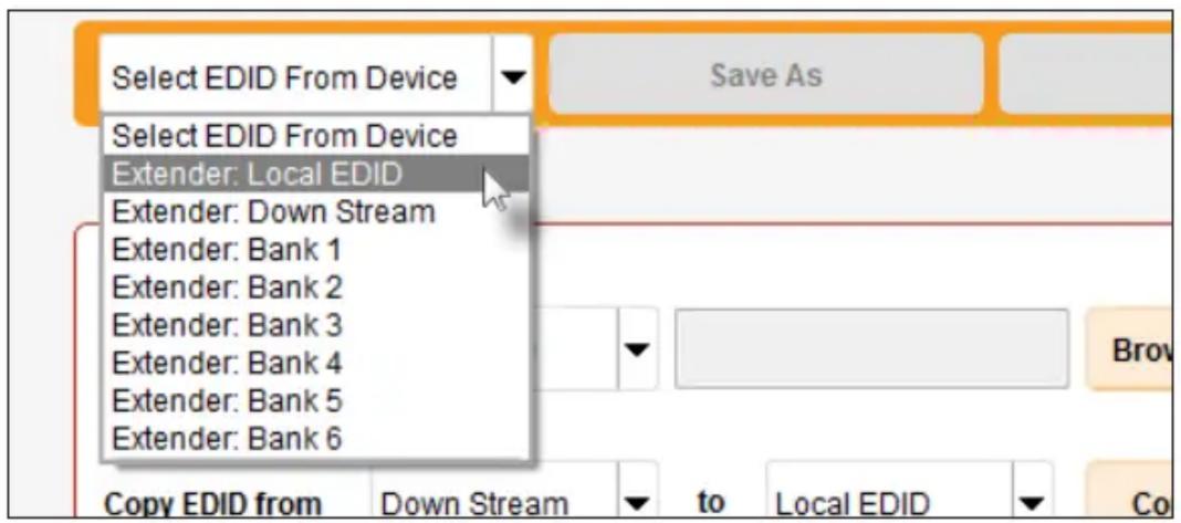
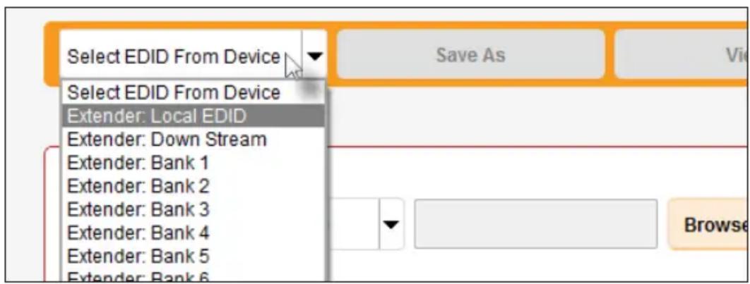
- Click the drop-down list next to the Download button, and select the desired EDID. In this example, we will select Extender: Local EDID.
- Click the Save As button.

- The Windows Save File dialog will be displayed. Select the desired folder and specify the name of the file in the File name field, within the Save File dialog. Make sure to specify the .bin extension to the filename.
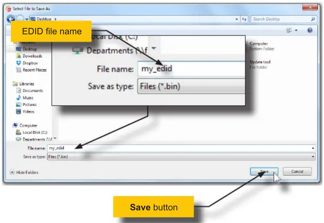
- Click the Save button.
Uploading an EDID
- Click the Manage a Product button and select the connected product from the drop-down list.
- Click the Manage EDID tab.
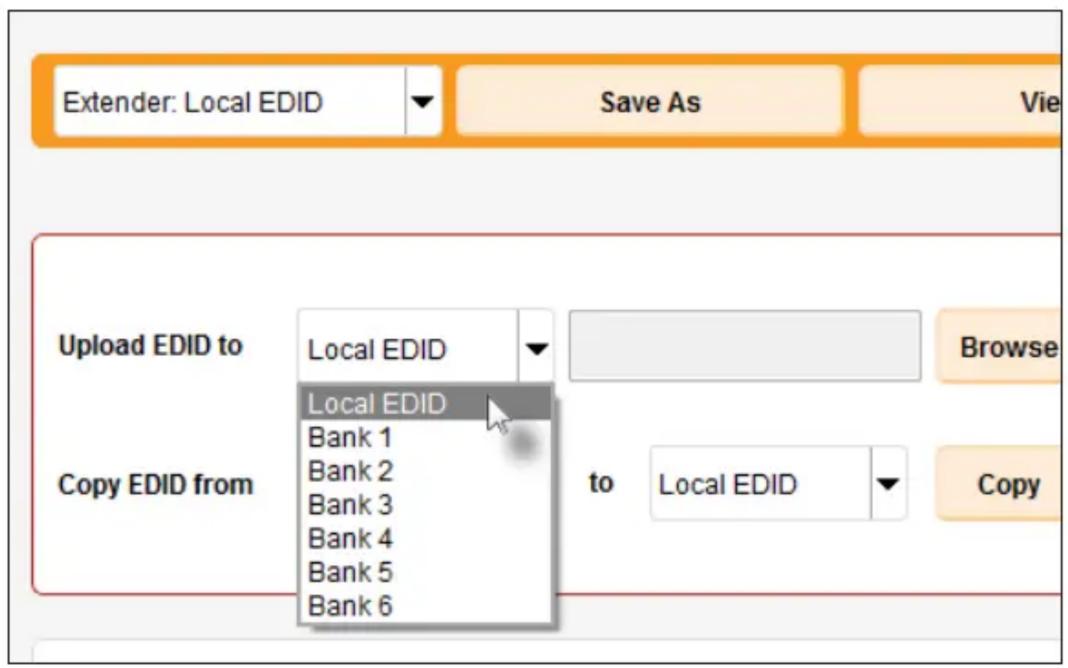
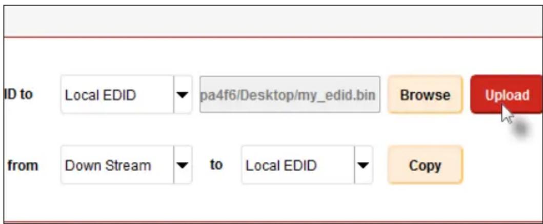
- Click the Upload EDID to drop-down list to select the location where the EDID will be uploaded. The EDID can be uploaded to the Local EDID or an EDID bank.
In the example below, we will select Local EDID.
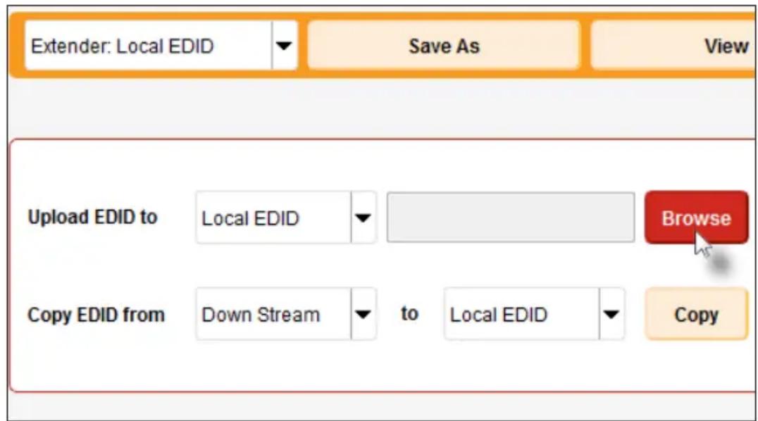
- Click the Browse button.
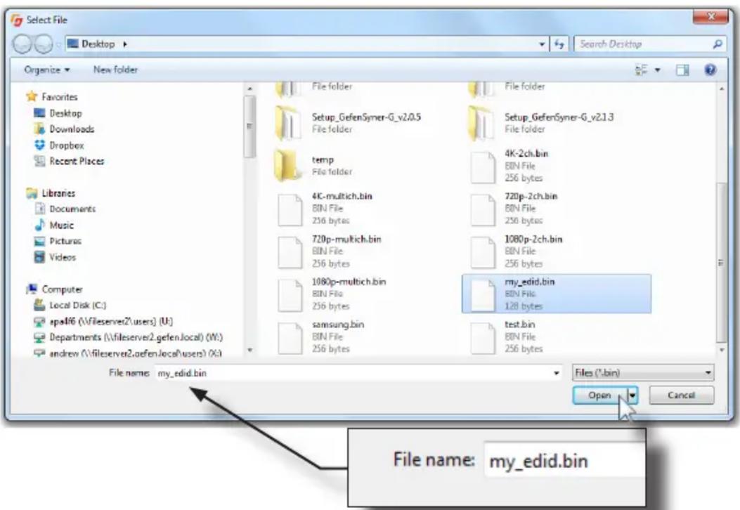
- The Windows Select File dialog will be displayed.
- Select the desired EDID file. The EDID file must be in .bin format.
- Click the Open button.
- Click the Upload button.
- In the lower-left corner of the interface, the "Upload..." message will appear as the EDID is uploaded. Once the operation is complete, the "Upload Complete." message will be displayed.


Copying an EDID
- Click the Manage a Product button and select the connected product from the drop-down list.
- Click the Manage EDID tab.
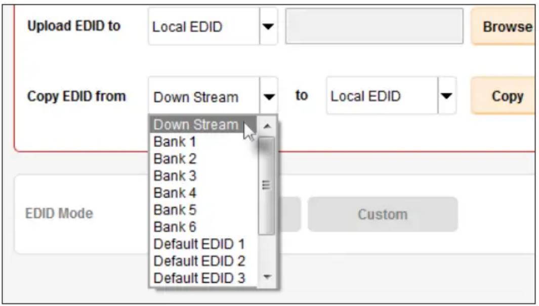
- Click the Copy EDID from drop-down list to select the location from where the EDID will be copied. The EDID can be copied from any of the following locations: The downstream EDID, an EDID bank, or a default EDID location
In the example below, we will select Down Stream.
- Click the Copy EDID to drop-down list to select the location to where the EDID will be copied. The EDID can by copied to the Local EDID or to an EDID bank.
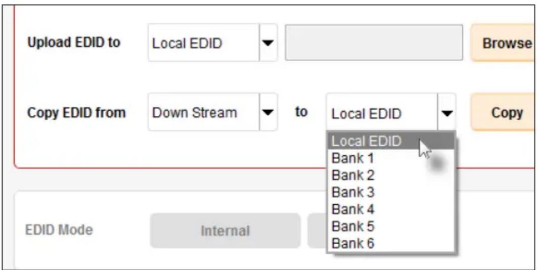
5. Click the Copy button.
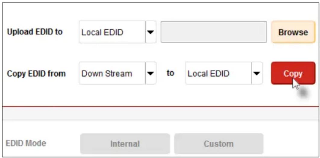
- In the lower-left corner of the interface, the "Copying..." message will appear as the EDID is uploaded. The copy-result message will vary, depending upon the copy operation.

In this example, since we copied the downstream EDID to the local EDID, the "Copy result: Downstream stored to local." message is displayed.
Viewing an EDID
- Click the Manage a Product button and select the connected product from the drop-down list.
- Click the Manage EDID tab.
- Click the Select EDID From Device / Display drop-down list to select the desired EDID.
Note that the display, which is connected to the computer, is also available in the drop-down list. In this way, we can download, view, and/or edit the EDID from the display (sink) device.
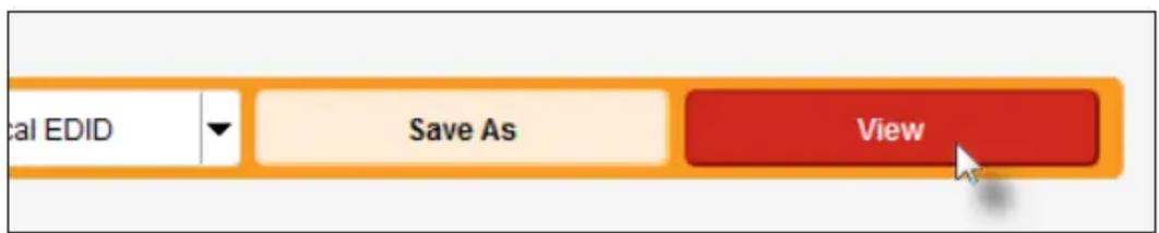
- Click the View button.
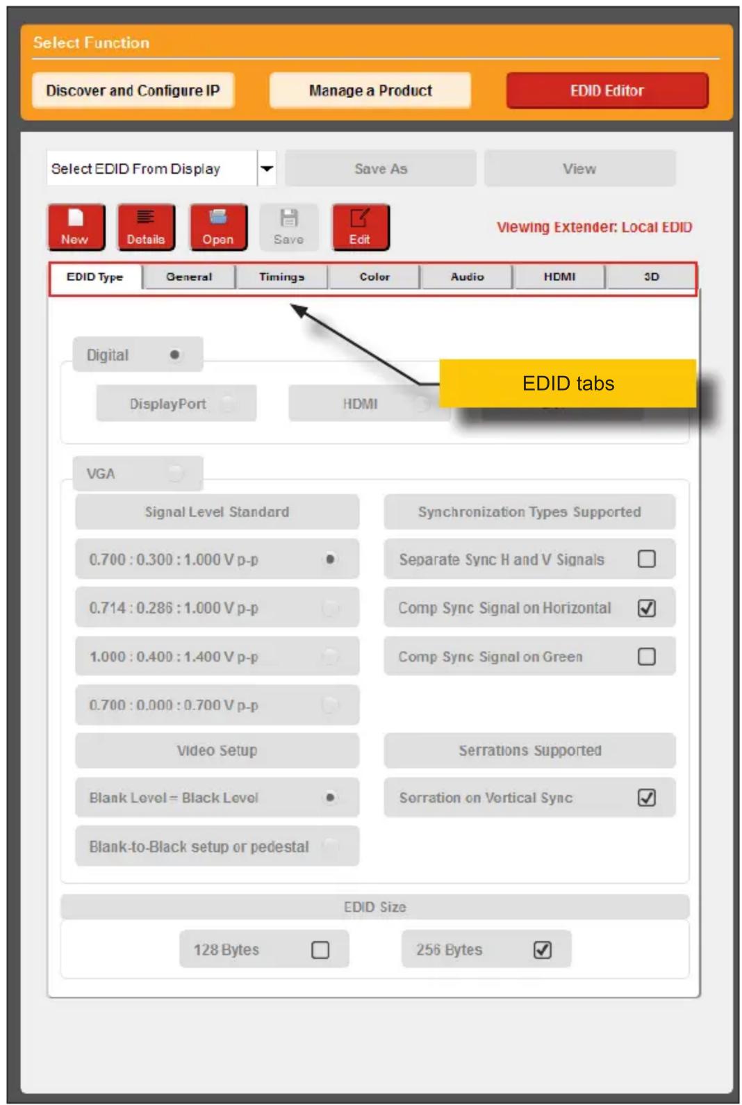
- After a few seconds, Syner-G will also switch to the EDID Editor screen.
See the Gefen Syner-G™ User Manual for more information on using the EDID Editor.
- Click the desired EDID tab to view specified information on the EDID. Note that some sections within a tab use scroll bars to indicate that more information is available.
7. Click the Details button.
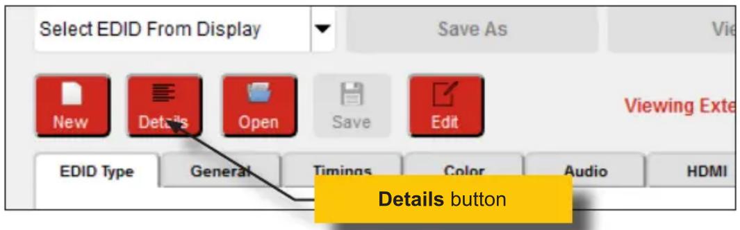
8. The EDID Summary window will be displayed. Use the horizontal and vertical scroll bar, as needed, to view the EDID information.
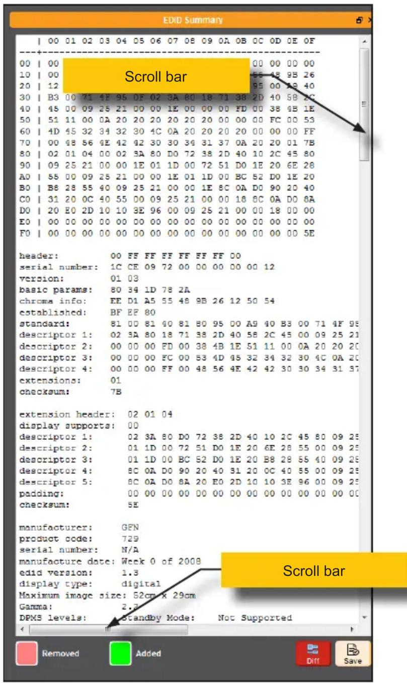
- Click the button, in the upper-right corner of the EDID Summary window to separate the EDID Summary window from the main Syner-G window:
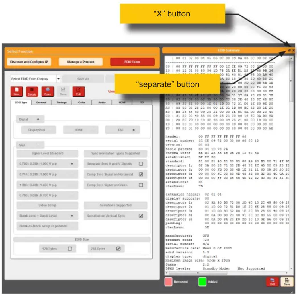
- Double-click the window title bar of the detached EDID Summary to reattach it to the main window. It to the main Syner-G window.
- To close the EDID Summary window, either click the × button, in the upper-right corner of the EDID Summary window or click the Details button in the main Syner-G window.
Link Quality Monitoring
The Status tab provides information about signal quality in HDBaseT installations. This page will only be available when connected to a Gefen product that uses HDBaseT technology.
- Select an HDBaseT product from the Select Product drop-down list. In this example, the EXT-UHDA-HBT2 is selected. Make sure to select GTB-UHD-HBT2.

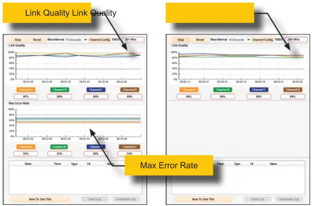
- Under the Status tab will automatically be selected. If a Sender unit is selected, both the Link Quality and Max Error Rate graphs will be displayed. If a Receiver unit is selected, only the Link Quality graph will be displayed.
Sender unit Receiver unit
- Click the Channel Config button, above the Link Quality graph.

- The Select a Channel Configuration dialog box will be displayed.
- Click the radio button for the cable termination type. In the example, below, T-568B is selected.
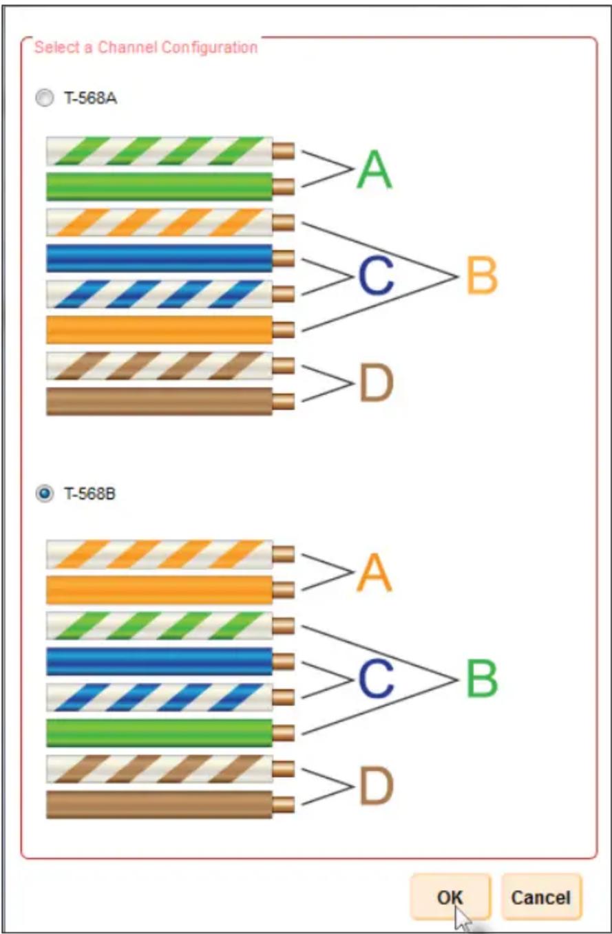
-
Click the OK button to save the selection.
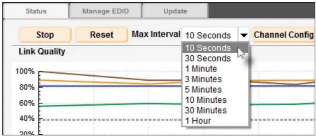
-
Click the Max Interval drop-down list to select the desired time interval. This interval represent the maximum length of time before the graphs are updated.
- To clear the channel data from both graphs, click the Reset button. Click the Stop button to halt the link monitoring process.
When the Stop button is clicked, the monitoring process will stop and the button will read Start. In addition, Syner-G will ask if the log file should be saved. To continue the monitoring process, click the Start button.

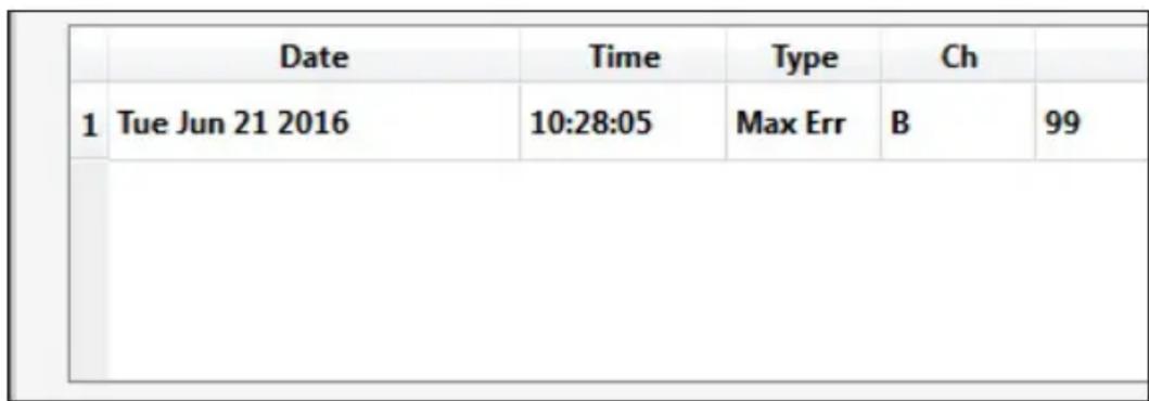
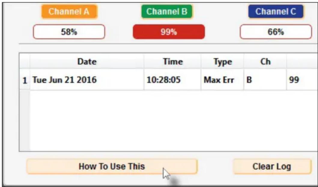
- Errors are automatically recorded and placed in the list box at the bottom of the Syner-G application, as shown.
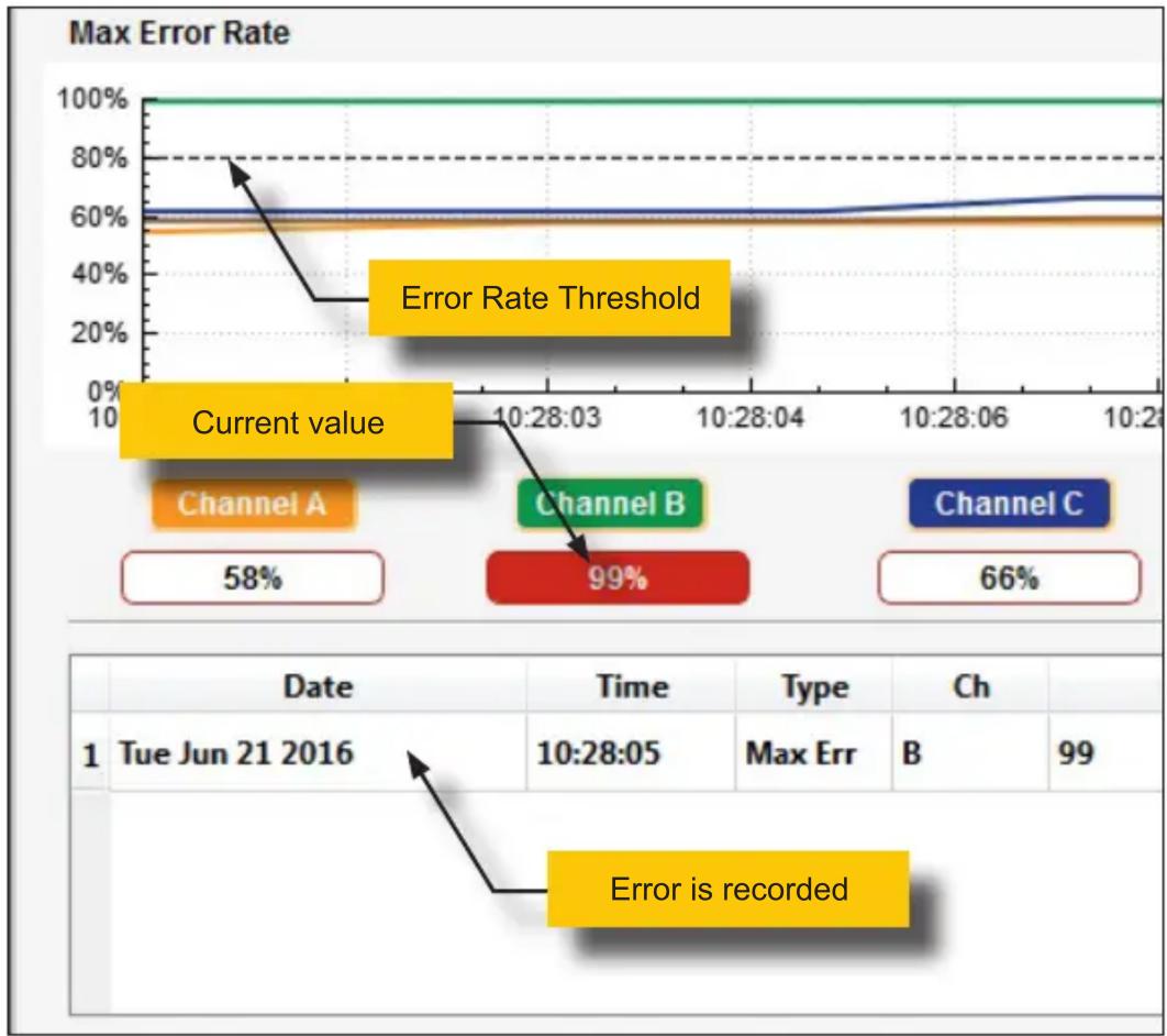
In the example, below, the Max Error Rate for Channel B is 100% . Note the horizontal dashed-line at the 80% mark. This line represents the error rate threshold for each channel.
Since Channel B has exceeded the threshold, the channel's current value is highlighted in red, as shown below.
The following table provides a summary of the error type and the values that will trigger an error report. Note that a threshold value will also trigger a report.
| Report Type Range when value is recorded | |
| Link Quality 40% or below | |
| Max Error Rate 80% or above | |
- Press the Clear Log button, at any time, to clear all log entries.
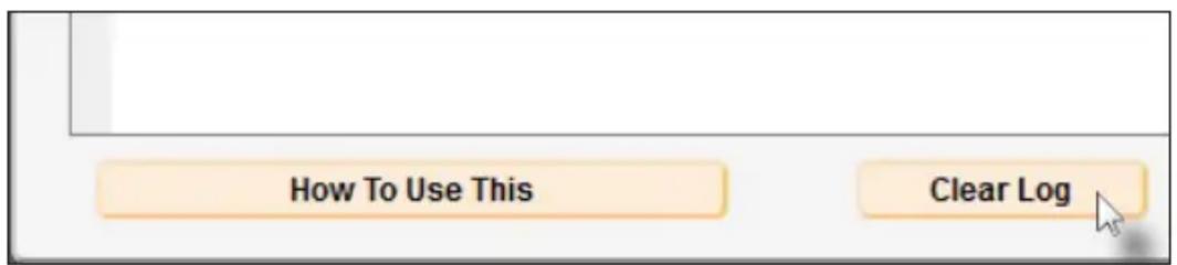
Once the Clear Log button is pressed, the following dialog will be displayed, confirming the operation.
Click the No button to clear all reports in the list box. Note that once cleared, reports can not be recovered.
Click the Yes button to save the all current data to a .csv file. See the next step for more information on saving the current data to a file.

- Click the Download Log button to save all recorded error reports to a .csv file. The .csv file is a comma-delimited file which allows data to be saved in a structured, table-type format, which can be opened using a spreadsheet application.
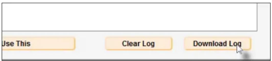
The Save CSV dialog will be displayed.
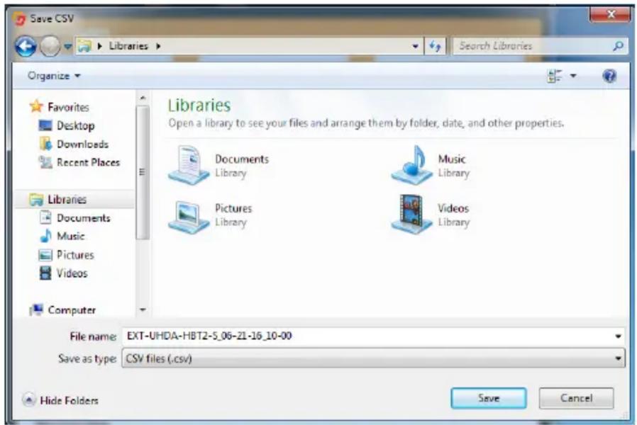
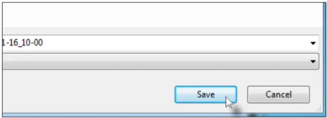
The filename will automatically be created and assigned to the Filename field. The name of the file can be changed, if desired.
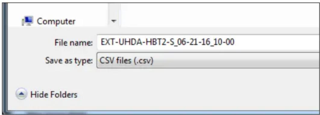
Click the Save button to save the file.
- To display detailed information on the use of Link Monitoring, click the How to Use This button, at the bottom of the Syner-G application window.
The How to use this page dialog will be displayed. It is recommended that this dialog be read in it entirety as it provides technical details on link monitoring.
To dismiss the dialog, click the OK button at the bottom of the dialog.

How to use this page.
X

This monitoring tab has been designed to give the installer an indication of cable or installation issues that may be present in your HDBaseT™ 2.0 setup. Information displayed here can help troubleshoot problems that may result in a loss of picture or quality. While a video signal may be displayed while marginal values are being recorded here, intermittent issues, such as EMI interference, can be introduced which may cause a momentary loss of signal. The values displayed below are general guidelines to ensure that a proper signal is being both transmitted and received
The Max Error Rate graph (Transmitter Only) will display the general quality of the signal on the cable being used. The lower the value the better. This is an excellent indicator of general cable quality. If this signal is constantly at 100% , there may be an issue with the cable and replacement using a higher quality cable may be necessary. If using UTP (unshielded twisted pair) cabling, using a high quality STP (shielded twisted pair) may help alleviate issues. If the value of the signal hovers above 80% over time, the link is considered marginal. Although an output signal may be present, the signal may be susceptible to interference that cannot be compensated for and a signal loss may occur. Values below 80% are considered acceptable, and while momentary spikes above the 100% mark may be detected, and average signal that lies below the 80% level is considered good. Values above 80% are recorded.
Link Quality (Transmitter and Receiver, however the Receiver side is considered more important for overall Link Quality evaluation) is displayed as pairs of signals that directly relate to the pair of cables present in the link cable. The higher the value the better. This is an excellent indicator of issues that may be present with a particular pair. Bad termination of cabling may be the cause of issues when a particular pair is showing marginal performance and is constantly dropping below the 38% value. If a particular pair is deviating from all of the others, a re-termination of the cable-end may solve the problem. If all pairs are displaying performance below 38% over time, this is indicative of a bad cable and should be replaced with a higher quality cable. Re-termination of both ends should be considered first if in-field termination was initially performed during installation. Values above 38% are considered acceptable, although a value closer to 100% is preferred. Values below 38% are recorded.
The graphs this tab can be used together to determine the overall quality of the link cable. Environmental forces may also cause momentary spikes in the values, but every effort to compensate for these forces has been taken in the product design, and ensuring that a high quality link cable with proper termination is the best solution to avoiding potential issues. In the event that a high quality cable is being used, and proper cable termination has been verified, environmental issues that cause values to be skewed may be the cause of signal issues. Inordinate amounts of interference can skew the results of these graphs, and the cable's placement in an installation may need to be moved to alleviate these issues.

This page left intentionally blank.

HDBaseT™ Extender
w/ RS-232, 2-way IR, and POH
4 Appendix
The Syner-G™ Software Suite provides an easy way to perform firmware updates. Before launching Syner-G™, makre sure that a USB cable is connected between the product and the computer that is running the Syner-G™ software. Refer to the Syner-G™ Software Suite User Manual for more information on using other features with this product.
- Launch the Syner-G™ Software Suite from the Start Menu or using the shortcut from the Windows Desktop.

Gefen
Syner-G
- Click the Manage a Product button.
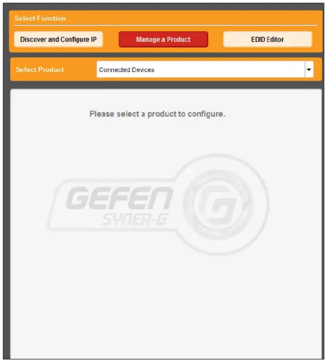
- Select the product from the Select your product drop-down list.
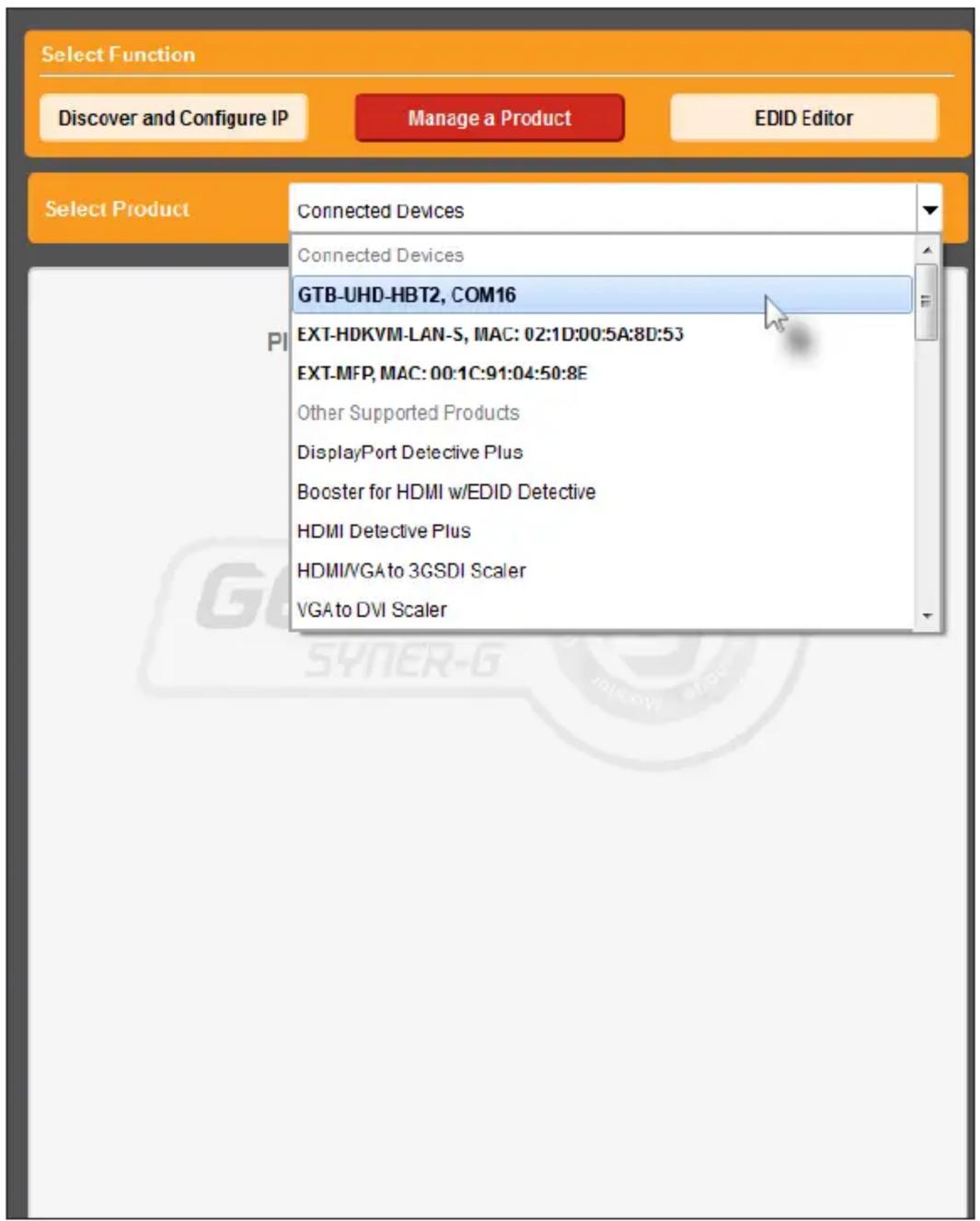
If the product is not detected by Syner-G™, then the product will not be listed in bold type, within the Select your product drop-down list. Verify the following:
The product is powered and connected to the computer that is running the Syner-G™ Software Suite, using a USB-to-Mini USB cable.
Make sure that the USB driver is installed and functioning correctly under Control Panel. See Verifying the USB Driver (page 24) for more information.
- Click the Update tab.
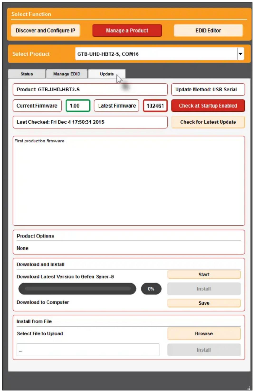
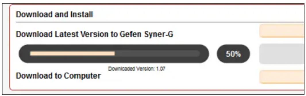
- Click the Start button to begin downloading the firmware.
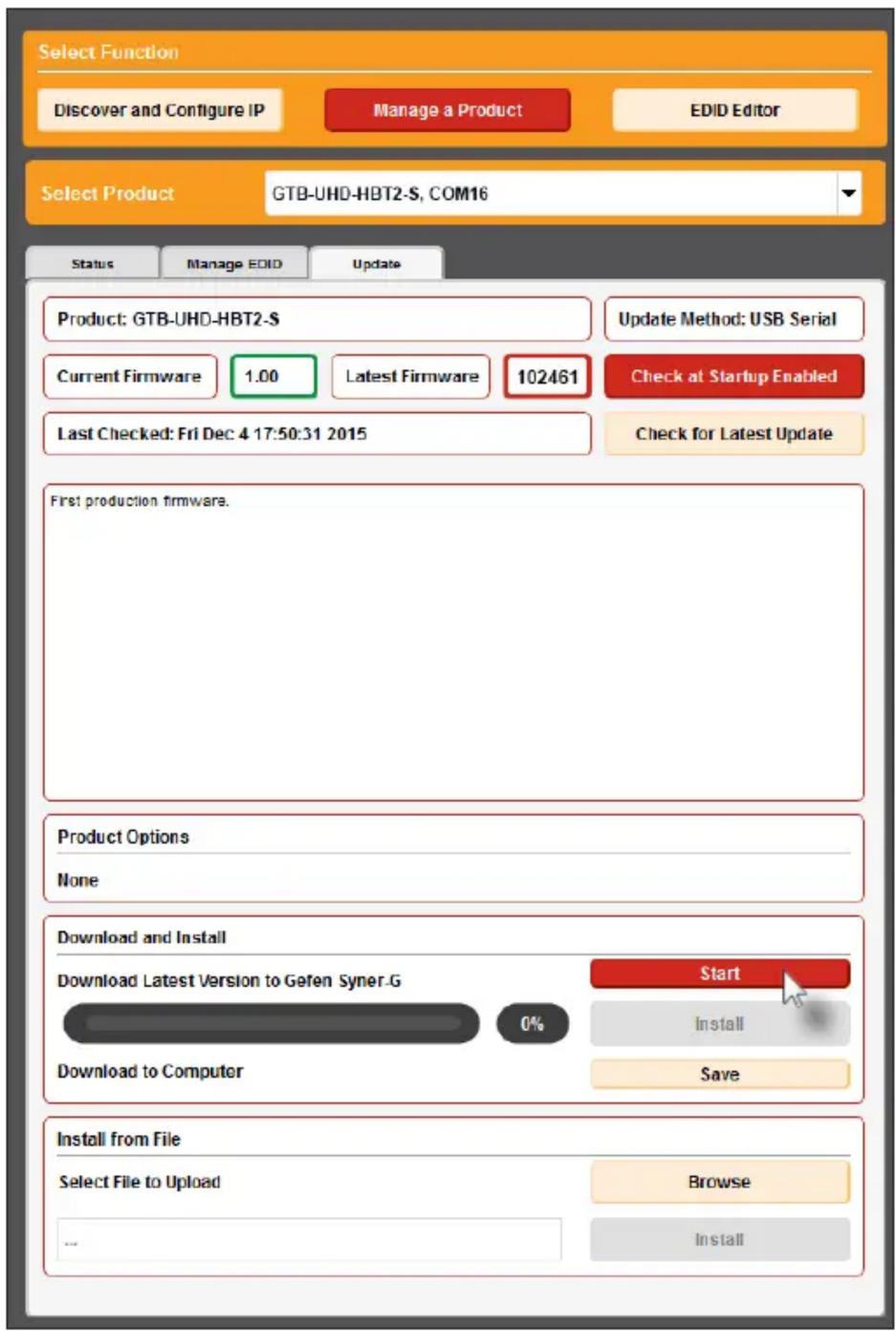
The Syner-G™ Software Suite will automatically download the firmware file for the selected product. This process should take a few seconds.
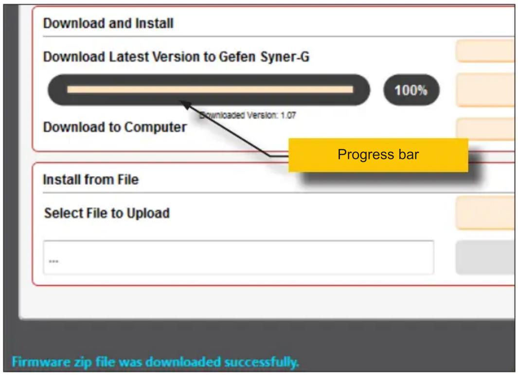
Once the download process has completed, the progress bar will indicate 100% , as shown on the next page.
A message will also appear at the bottom of the window, indicating that the firmware file was successfully downloaded.
- Click the Install button to begin installing the software.
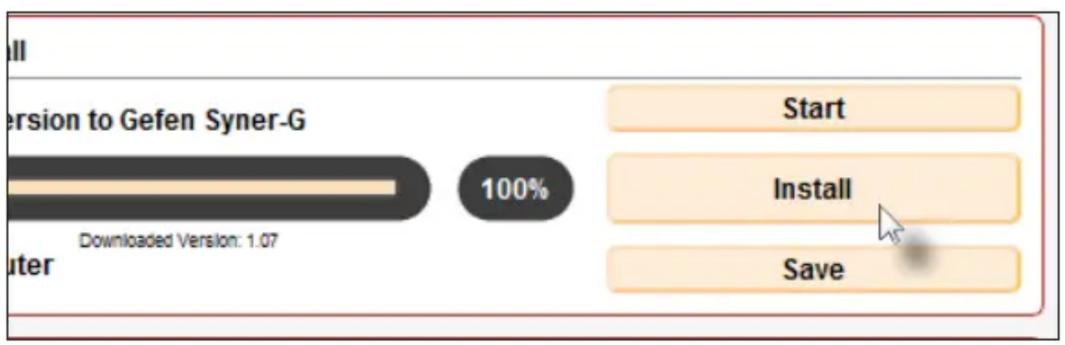
- The installation process will begin and the progress bar will indicate the current status.
- After the firmware update process has completed, the following message will be displayed.
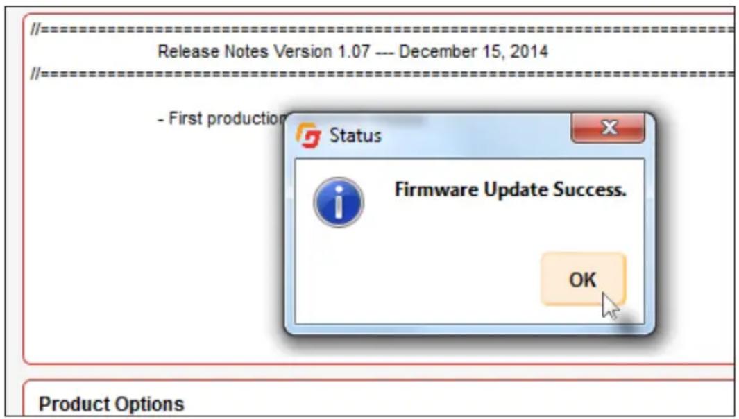
- Click the OK button to dismiss the message box.
- The procedure is now complete.
Sender Unit DIP Switches
| DIP switich Funciton Default setting (OFF position) | |
| 1 EDID mode Pass-through (downstream) EDID | |
| 2 Hot-Plug Detect (HPD) Always high | |
| 3 EDID lock Disabled | |
| 4 HDCP Pass-through | |
| 5 Sender IR carrier Pass-through | |
| 6 Receiver IR carrier Pass-through | |
| 7 IR polarity Uses Gefen part no. EXT-RMT-EXTIRN | |
| 8 Long-Reach mode HDBT Mode | |
| 9 IR carrier frequency 38 kHz | |
| 10 IR carrier frequency Depends on DIP 5 setting | |
| 11 N/A --- | |
| 12 N/A --- | |
Receiver Unit DIP Switches
| DIP swtich Funciton Default setting (OFF position) | ||
| 1 Sender IR carrier Pass-through | ||
| 2 Receiver IR carrier Pass-through | ||
| 3 IR polarity Uses Gefen part no. EXT-RMT-EXTIRN | ||
| 4 Long-Reach mode HDBT Mode: Extend 4K up to 330 ft (4:2:0) | ||
| 5 IR carrier frequency 38 kHz | ||
| 6 IR carrier frequency Depends on DIP 1 setting | ||
| 7 N/A --- | ||
| 8 N/A --- | ||
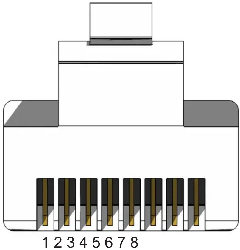
Front of RJ-45 Connector
Gefen recommends the TIA/EIA-568-B wiring option. Use the table below when field-terminating cable for use with Gefen products.
Pin Color Description
1 Orange / White TD+ (Transmit Data, positive differential signal)
2 Orange TD- (Transmit Data, negative differential signal)
3 Green / White RD+ (Receive Data, positive differential signal)
4 Blue Unused
5 Blue / White Unused
6 Green RD- (Receive Data, negative differential signal)
7 Brown / White Unused
8 Brown / White Unused
Supported Formats
Resolutions (max.) 3840 × 2160 p 60 Hz (4:2:0)
- 4096 × 2160p30 Hz( 4 : 4 : 4)
- 3840 × 2160p30 Hz( 4 : 4 : 4)
Connectors, Controls, and Indicators
HDMI In (Sender) · 1 x Type A 19-pin female, locking
HDMI Out (Receiver) • 1 x Type A 19-pin female, locking
RS-232 (Sender) · 1 x DB-9, female
RS-232 (Receiver) · 1 x DB-9, male
Link (Sender / Receiver) • 1 x RJ-45
IR In / Ext (Sender / Receiver) • 1 x 3.5mm mini-stereo
IR Out (Sender / Receiver) · 1 x 3.5mm mini-mono
POH 48V DC (Sender) · 1 x power connector
Non-POH 48V DC (Receiver) · 1 x power connector
USB (Sender / Receiver) • 1 x mini-B type
DIP switches (Sender) · 12 x piano type, 4 per bank
DIP switches (Receiver) • 8 x piano type, 4 per bank
Link Indicator (Sender / Receiver)
Video Indicator (Sender / Receiver)
Power Indicator (Sender / Receiver)
Operational
Maximum pixel clock 300 MHz
Power input 48 V DC
Power consumption (Sender/Receiver,combined) 11W
Operating temperature · +32 to +122^ (0 to +50^)
Operating humidity 5 % to 90 % RH, non-condensing
Storage temperature -4 to +185^ (-20 to +85^)
Storage humidity 0% to 95% RH, non-condensing
MTBF 50000 hours
Physical
Dimensions (W x H x D) 5.8" x 1" x 3.4" (146mm x 25mm x 85mm) (not including connectors)
Unit weight 0.50 lbs (0.23 kg) each
A
Application Diagram 7
B
Bidirectional IR Control controlling the display 17 controlling the source 16 from different locations 18
C
Connection Instructions 6
D
Default Settings receiver unit, DIP 52 sender unit, DIP 52
DIP Switch Configuration 10
receiver unit 13
sender unit 10
E
EDID
copying 31
downloading 26
hot-plug detect 10
local / pass-through 10
lock 11
uploading 29
viewing 33
F
Features vi Firmware updating 46
H
HDCP control 11
1
IR carrier notes 14 receiver unit 11 sender unit 11
IR Carrier Frequency 12, 13, 14
IR polarity 11, 13
L
LED Status 15
Link Quality 37
channel configuration 37
clearing logs 40
error logging 39
help 42
link quality graph 37
max error rate graph 37
max interval 39
saving logs 41
start monitoring 39
stop monitoring 39
thresholds 40
Long-Reach Mode 11, 14
N
Network Cable Diagram 53
P
Packing List vii
R
Receiver Unit 4 RS-232 Interface 19
S
Sender Unit 2
Specifications 54
Syner-G
copying an EDID 31
downloading an EDID 26
link quality. See Link Quality
uploading an EDID 29
verifying the USB Driver 24
viewing an EDID 33
T
Table of Contents viii
U
Updating the Firmware 46
USB Driver 24

GEFEN
1800 S McDowell Blvd. Petaluma CA 94954
(707) 283-5900 (800) 472-5555