
ACRMD4KI-1 - Climatiseur APC - Notice d'utilisation et mode d'emploi gratuit
Retrouvez gratuitement la notice de l'appareil ACRMD4KI-1 APC au format PDF.


| Type d'appareil | Climatiseur rackmount |
| Puissance de refroidissement | 3,5 kW |
| Installation | Montage en rack |
| Type de refroidissement | Air |
| Alimentation électrique | Non précisé |
| Dimensions | Non précisées |
| Poids | Non précisé |
| Débit d'air | Non précisé |
| Niveau sonore | Non précisé |
| Type de contrôle | Non précisé |
| Utilisation | Refroidissement de matériel électronique en rack |
| Type de fluide frigorigène | Non précisé |
| Protection | Non précisée |
| Poignée de transport | Oui |
| Date de sortie | 06/2019 |
| Fabricant | Non précisé |
FOIRE AUX QUESTIONS - ACRMD4KI-1 APC
Questions des utilisateurs sur ACRMD4KI-1 APC
0 question sur cet appareil. Repondez a celles que vous connaissez ou posez la votre.
Poser une nouvelle question sur cet appareil
Téléchargez la notice de votre Climatiseur au format PDF gratuitement ! Retrouvez votre notice ACRMD4KI-1 - APC et reprennez votre appareil électronique en main. Sur cette page sont publiés tous les documents nécessaires à l'utilisation de votre appareil ACRMD4KI-1 de la marque APC.
MODE D'EMPLOI ACRMD4KI-1 APC
Rackmount 3.5-kW Air Conditioning Unit
User Manual
ACRMD4KI-1, ACRMD4KI-2, ACRMD4KI-3
990-6186-001
Release Date: 06/2019
Legal Information
The Schneider Electric brand and any trademarks of Schneider Electric SE and its subsidiaries referred to in this guide are the property of Schneider Electric SE or its subsidiaries. All other brands may be trademarks of their respective owners.
This guide and its content are protected under applicable copyright laws and furnished for informational use only. No part of this guide may be reproduced or transmitted in any form or by any means (electronic, mechanical, photocopying, recording, or otherwise), for any purpose, without the prior written permission of Schneider Electric.
Schneider Electric does not grant any right or license for commercial use of the guide or its content, except for a non-exclusive and personal license to consult it on an "as is" basis. Schneider Electric products and equipment should be installed, operated, serviced, and maintained only by qualified personnel.
As standards, specifications, and designs change from time to time, information contained in this guide may be subject to change without notice.
To the extent permitted by applicable law, no responsibility or liability is assumed by Schneider Electric and its subsidiaries for any errors or omissions in the informational content of this material or consequences arising out of or resulting from the use of the information contained herein.
Table of Contents
Safety 5
Important Safety Instructions — SAVE THESE INSTRUCTIONS.5
Safety During Installation and Operation.. 6
Intended Use 8
General Information 9
Document Overview 9
Original Instructions 9
Save These Instructions 9
Manual Updates 9
Cross-Reference Symbol Used in This Manual. 9
Abbreviations 9
Equipment Disposal 9
General Information 9
Please Recycle 10
Waste Electrical and Electronic Equipment (WEEE) Disposal 10
Receiving and Inspecting the Unit 10
Filing a Claim. 10
Storing the Unit Before Installation 10
Unpacking the Unit 11
Moving the Unit 11
Unit Overview 12
Introduction 12
Equipment Guidelines 13
Working Conditions and Environmental Limits. 13
Standard Features and Options 14
Standard Features 14
Optional Features 15
Technical Data 15
Dimensions and Weights 17
Indoor Unit 17
Outdoor Units 17
Weight 18
Service Clearance 18
Airflow Clearance 18
Access Locations 19
Component Identification 20
Inventory 20
External Components 20
Indoor Unit 20
Outdoor Unit 21
Internal Components 22
Indoor Unit 22
Outdoor Unit 23
Installation 24
Site Preparation 24
Incoming Power Supply Requirements 24
Before You Start 24
Positioning Units. 25
Panel Removal 26
Indoor Unit 26
Outdoor Unit 27
Display Interface 28
Mechanical Connections 28
Installing the Indoor Unit in the Rack 28
Installing the Outdoor Unit 29
Piping Kit Application 30
Refrigerant Piping 31
Drain Connection 36
Electrical Connections 37
Wire Cross-Section Ratings 38
Connection Interface 39
Charging the Refrigeration System 42
Leak Detection 42
Vacuum Pumping. 43
Calculating the Refrigerant Charge 44
Charging the Refrigerant 45
Commissioning 46
Start-Up Inspection Checklist 46
Electrical Inspection Checklist 47
Mechanical Inspection Checklist 48
Operation 49
Using the Display. 49
Maintenance 56
Preventive Maintenance. 56
Safety
Important Safety Instructions — SAVE THESE INSTRUCTIONS
Read these instructions carefully and look at the equipment to become familiar with it before trying to install, operate, service or maintain it. The following safety messages may appear throughout this manual or on the equipment to warn of potential hazards or to call attention to information that clarifies or simplifies a procedure.

The addition of this symbol to a "Danger" or "Warning" safety message indicates that an electrical hazard exists which will result in personal injury if the instructions are not followed.

This is the safety alert symbol. It is used to alert you to potential personal injury hazards. Obey all safety messages with this symbol to avoid possible injury or death.
DANGER
DANGER indicates a hazardous situation which, if not avoided, will result in death or serious injury.
Failure to follow these instructions will result in death or serious injury.
WARNING
WARNING indicates a hazardous situation which, if not avoided, could result in death or serious injury.
Failure to follow these instructions can result in death, serious injury, or equipment damage.
CAUTION
CAUTION indicates a hazardous situation which, if not avoided, could result in minor or moderate injury.
Failure to follow these instructions can result in injury or equipment damage.
NOTICE
NOTICE is used to address practices not related to physical injury. The safety alert symbol shall not be used with this type of safety message.
Failure to follow these instructions can result in equipment damage.
Please Note
Electrical equipment should only be installed, operated, serviced, and maintained by qualified personnel. No responsibility is assumed by Schneider Electric for any consequences arising out of the use of this material.
A qualified person is one who has skills and knowledge related to the construction, installation, and operation of electrical equipment and has received safety training to recognize and avoid the hazards involved.
Safety During Installation and Operation
▲▲DANGER
HAZARD OF ELECTRIC SHOCK, EXPLOSION, OR ARC FLASH
- Apply appropriate personal protective equipment (PPE) and follow safe electrical work practices.
This equipment must be installed and serviced by qualified personnel only. - Turn off all power supplying this equipment before working on or inside the equipment.
- Replace all devices, doors, and covers before turning on power to this equipment.
Always use a properly rated voltage sensing device to confirm power is off. - If the power supply cord is damaged, it must be replaced by an equivalent cord or assembly available from the manufacturer or its service agent.
Failure to follow these instructions will result in death or serious injury.
WARNING
ELECTRICAL HAZARD
- Electrical service must conform to local and national electrical codes and regulations.
The equipment must be grounded.
Failure to follow these instructions can result in death, serious injury, or equipment damage.
WARNING
HAZARD FROM MOVING PARTS
Keep hands, clothing, and jewelry away from moving parts. Check the equipment for foreign objects before closing the doors and starting the equipment.
Failure to follow these instructions can result in death, serious injury, or equipment damage.
WARNING
DAMAGE TO EQUIPMENT OR PERSONNEL
- The equipment is heavy. For safety purposes, adequate personnel must be present when moving this item.
- The load must always be solidly anchored to the bearing element of the lifting equipment and means of transport.
- No one should be near the suspended load, nor in the working area of the crane, forklift, truck, or any other lifting equipment or means of transport.
Failure to follow these instructions can result in death, serious injury, or equipment damage.
▲WARNING
HAZARD TO EQUIPMENT OR PERSONNEL
This equipment is not to be operated or installed by persons with reduced physical, sensory, or mental capabilities, or persons lacking experience or knowledge unless they have been given supervision or instruction. Children are not to operate or play on or around this equipment.
Failure to follow these instructions can result in death, serious injury, or equipment damage.
CAUTION
HAZARD FROM UNPROTECTED OUTPUT
Apply circuit protection to all outputs.
Failure to follow these instructions can result in injury or equipment damage.
CAUTION
HAZARD TO EQUIPMENT OR PERSONNEL
Do not operate your air conditioner in a wet room such as a bathroom or laundry room.
Failure to follow these instructions can result in injury or equipment damage.
NOTICE
STATIC ELECTRICITY HAZARD
Circuit boards contained within this unit are sensitive to static electricity. Use one or more electrostatic-discharge devices while handling the board.
Failure to follow these instructions can result in equipment damage.
NOTICE
DAMAGE FROM EXPOSURE
Leaving the equipment uncovered and exposed to possible damage from the environment will void the factory warranty.
Failure to follow these instructions can result in equipment damage.
NOTICE
DAMAGE TO REFRIGERATION CIRCUIT
- Make sure the compressor has been pre-heated for at least 24 hours in the event the system is not in operation for an extended period of time.
Failure to follow these instructions can result in equipment damage.
NOTICE
DAMAGE TO EQUIPMENT
- If the power supply cord is damaged, it must be replaced by the manufacturer.
- An all-pole disconnection device that has at least 3-mm clearances in all poles and has a leakage current that may exceed 10mA , the residual current device (RCD) having a rated residual operating current not exceeding 30mA , and disconnection must be incorporated in the fixed wiring in accordance with the wiring rules.
Type and rating of fuses: glass tube 250 V, 3.15 A
Failure to follow these instructions can result in equipment damage.
Intended Use
The cooling units provide air conditioning within the limits and methods described in this manual. This equipment must be installed and applied in accordance with the instructions provided. No modifications may be made to the units or their parts without explicit written consent from Schneider Electric. Any mechanical or electrical modification voids factory warranty.
General Information
Document Overview
Original Instructions
These are the original instructions provided by the manufacturer.
Save These Instructions
This manual contains important instructions that must be followed during installation, operation, and maintenance of the cooling unit.
Manual Updates
Schneider Electric™ policy is one of continuous technological innovation and the company reserves the right to amend any data herein without prior notice. The images shown in this manual are for descriptive purposes only and they may differ from specific models that are selected.
NOTE: Unit images and component identification information are examples only. The final configuration of the unit may change according to the different options.
Check for updates to this manual on the Schneider Electric Web site, www.schneider-electric.com/support. Select the Download Documents and Software link under the Support tab and enter the manual part number or SKU for your equipment in the search field. See the back cover of this manual for the part number.
Cross-Reference Symbol Used in This Manual

See another section of this document or another document for more information on this subject.
Abbreviations
The following abbreviations and terms are used in this manual:
CFD: Computational fluid dynamics
- EXV: Electronic expansion valve
PTC: Positive Temperature Coefficient
Equipment Disposal
General Information
- This air-conditioning unit contains fluorinated greenhouse gases.
- Installation, servicing, maintenance, and repair of this unit must be performed by qualified personnel.
- Un-installation and recycling of the product must be performed by qualified personnel.
- When the unit is checked for leaks, proper record keeping of all checks is strongly recommended.
Please Recycle
The shipping materials are recyclable. Save them for later use, or dispose of them appropriately.
Waste Electrical and Electronic Equipment (WEEE) Disposal

Schneider Electric products comply with international directives on the Restriction of Hazardous Substances (RoHS) in electronic and electrical equipment and the disposal of Waste Electrical and Electronic Equipment (WEEE). Dispose of any waste electronic or electrical equipment with the appropriate recycling center. Contact Schneider Electric for assistance.
Receiving and Inspecting the Unit
The cooling unit is packaged in a wooden crate or anchored to a pallet and covered with transparent film.
Upon delivery, check that the unit is intact and immediately notify the carrier in writing of any damage that can be attributed to careless or improper transportation. Check for any damage on the area upon which the display interface is mounted.
In case of shipping damage, do not operate the cooling unit. Keep all packaging for inspection by the shipping company and contact Schneider Electric Corporation.
Filing a Claim
If damage is identified on receipt of the equipment, note the damage on the bill of lading and file a damage claim with the shipping company. Contact Schneider Electric Worldwide Customer Support at one of the numbers listed on the Web page on the back page of this manual for information on how to file a claim with the shipping company. The shipping claim must be filed at the receiving end of the delivery.
NOTE: In case of shipping damage, do not operate the equipment. Keep all packaging for inspection by the shipping company and contact Schneider Electric.
Storing the Unit Before Installation
| NOTICE |
| DAMAGE FROM EXPOSURE |
| Leaving the equipment uncovered and exposed to possible damage from the environment will void the factory warranty. |
| Failure to follow these instructions can result in equipment damage. |
The storage environment for the series AC should comply with GB4798.1-2005.
| Item | Requirements |
| Storage environment | Indoor, clean (without dust) |
| Ambient humidity | 15–85%RH (without condensation) |
| Ambient temperature | -20 to 52°C (-4 to 129.2°F) |
Unpacking the Unit
Move the unit near its final position before unpacking it for inspection.
The unit is packed with corrugated paper. Remove all packing materials on site.
Moving the Unit
▲WARNING
DAMAGE TO EQUIPMENT OR PERSONNEL
- The equipment is heavy. For safety purposes, adequate personnel must be present when moving this item.
- The load must always be solidly anchored to the bearing element of the lifting equipment and means of transport.
- No one should be near the suspended load, nor in the working area of the crane, forklift, truck, or any other lifting equipment or means of transport.
Failure to follow these instructions can result in death, serious injury, or equipment damage.
Lifting and transporting the units must be carried out by qualified personnel as described in this manual.
Use all relevant safety standards to prevent any possible damage to people or objects.
Indoor Unit
The cooling unit is packaged in a carton. The recommended tools for moving and installing the equipment include the following:

Forklift

Pallet Jack
Outdoor Unit
The condensing unit is packaged in a carton. The recommended tools for moving and installing the equipment include the following:

Pallet Jack

Forklift

Crane
Keep the inclination of the outdoor unit within 75-105 degrees.

Unit Overview
Introduction
This AC unit series, an air conditioning system of precision environmental control in a server cabinet, provides precise temperature control, safety and reliability, high energy efficiency design, and remote monitoring.
This series also features efficient refrigeration, high reliability, high sensible-heat factor, intelligent monitoring, rapid installation, convenient maintenance, and compact structure. R410A refrigerant is used as required internationally for environmental protection.
Precise Temperature Control
This series of air conditioners has a temperature control of up to ± 2.0^ (3.6°F). Intelligent microprocessing control monitors any change in the server cabinet and responds with control processing in advance rather than reacting to the change of the environment at that time.
Safety and Reliability
Keep the unit running 24 hours a day to keep it reliable. The advanced microprocessing system of the units automatically adjusts machine operation and reduces faults. Automatic alarms and diagnostics aid in maintenance and servicing to help protect the unit and prolong the life of the unit.
High Energy Efficiency Design
The DC brushless, axial flow, centrifugal fan features minimal vibration, low noise, and high reliability. The high-efficiency, finned-tube heat exchanger greatly improves the heat exchange efficiency. The loop developed and verified to a specific model ensures each loop is uniformly distributed and the heat exchanger is fully used.
Remote Monitoring
Remote monitoring includes an RS485 interface and Modbus protocol.
- Telemetry Function: Remotely read the return and supply air temperature, humidity of return, and working state of the unit.
- Remote Function: Remotely read the open and close state, high or low temperature and return air humidity, and normal or failure fan state.
Cooling Control
- Temperature Control Function
- Indoor temperature controls system
Cooling Regulation Function
Variable-speed compressor
Cooling output range of 25-100% (16-90Hz)
Temperature
Regulated temperature range of 19 - 30^ C (66.2-86.0°F)
Adjustable temperature ± 2.0^ (3.6°F)
Equipment Guidelines
Working Conditions and Environmental Limits
Indoor Unit
| Limit Working Conditions | |
| Power Supply | 200–240 V~, 1 Ph, 50 Hz |
| Room Conditions | |
| Temperature | 16–43°C (60.8–109.4°F) |
| Humidity | 15%–65% RH (without condensation) |
| Maximum Altitude | 1000 m (3281 ft), de-rated for more than 1000 m (3281 ft) |
| Storage Conditions | |
| Temperature | -20 to 52°C (-4.0 to 129.2°F) |
Outdoor Unit
| Limit Working Conditions | |
| Power Supply | 200–240 V~, 1 Ph, 50 Hz |
| Ambient Conditions | |
| Temperature | -35.0 to 45.0°C (-31.0 to 113.0°F) |
| Maximum Altitude | 1000 m (3281 ft), de-rated for more than 1000 m (3281 ft) |
| Storage Conditions | |
| Temperature | -20 to 52°C (-4.0 to 129.2°F) |
Standard Features and Options
Standard Features
Indoor Unit
| Feature | Description |
| Evaporator | The finned tube heat exchanger with high-efficiency internal thread copper pipes, hydrophilic foil, CFD flow field analysis, and optimal matching improve the heat transfer efficiency. |
| EXV | The EXV improves the control precision and response speed for precision cooling while the system is stable to save energy. |
| Fan | The DC fan is continuously variable in speed and can quickly respond to heat loads. It features high airflow, high efficiency, long service life, and low noise. |
| Controller | The unit controller features power recovery and fault warning. It has a terminal block connection interface. |
| Filter | The aluminum air filter provides a clean air supply. |
Outdoor Unit
| Feature | Description |
| Compressor | The inverter-driven compressor adjusts the refrigerating capacity. The frequency conversion control technology of the compressor and the air supply temperature control of the unit enable the unit to flexibly adjust the refrigerating capacity under different heat loads, to provide a constant supply of air temperature, and reduce air temperature fluctuations. The running frequency of the compressor may be minimized under low thermal load conditions to ensure that the supply air temperature of the unit does not drop too low, and the compressor can be prevented from frequent start and stop to improve the efficiency and reliability of the unit and avoid condensation resulting from too low supply air temperature. |
| Fan | An axial flow, low-noise fan blade features wide voltage range and high reliability. The fan has multi-level air flow control, which improves the operation stability of the unit. |
| Condenser | Efficient finned-tube heat exchanger with hydrophilic fins does not retain dust and is easy to clean and maintain. |
Optional Features
| Feature | Description |
| Tube | The copper tube includes threaded joints, bell nuts, and insulation material for the outer package. The tube is sturdy, does not corrode easily, and withstands high temperature and high pressure. |
| Condensate Drain Pump | The low noise DC brushless water pump has a lift that reaches 5 meters (16.4 ft). |
| Low Ambient Temperature Kit | The low ambient temperature kit provides the capability to operate in temperatures below -15°C (-5°F). |
| Positive Temperature Coefficient (PTC) Heater | The structure is compact and the heating is uniform. The PTC heater installed in the indoor unit is used for heat compensation when the IT load is low. |
Technical Data
Indoor Unit
| Total Cooling Capacity | 3.6 kW (12,300 BTU/hr) |
| Sensible Cooling Capacity* | 3.5 kW (11,900 BTU/hr) |
| Rated Power Input | 200–240 V~, 1 Ph, 50 Hz |
| Rated Air Volume | 700 m³/h (410 SCFM) |
| Number of Fans | 1 |
| IDU Fan Input Power | 0.43 kW |
| Size of Liquid Pipe/Air Pipe Connection | 9.52/12.7 mm (0.37/0.50 in.) |
| Energy Efficiency Ratio (EER) | 2.5 |
| Sound Pressure Level | 62.5 dB(A) |
*Data at 35°C (95°F) RAT, 23%RH, outdoor air temperature 35°C (95°F)
Outdoor Unit
| Heat Exchange | 6.3 kW |
| Rated Air Volume | 1700 m3/h (1000 SCFM) |
| Input Power | 1.00 kW |
| Number of Fans | 1 |
| Number of Compressors | 1 |
| Sound Pressure Level | 51.5 dB(A) |
Refrigerant
| Refrigerant Type | R410A |
| Refrigerant Charge | 1.65 kg (58.2 oz) |
| CO2 Equivalent | 3.445 tonnes (7594.9 lb) |
| GWP | 2088 |
Dimensions and Weights
Indoor Unit
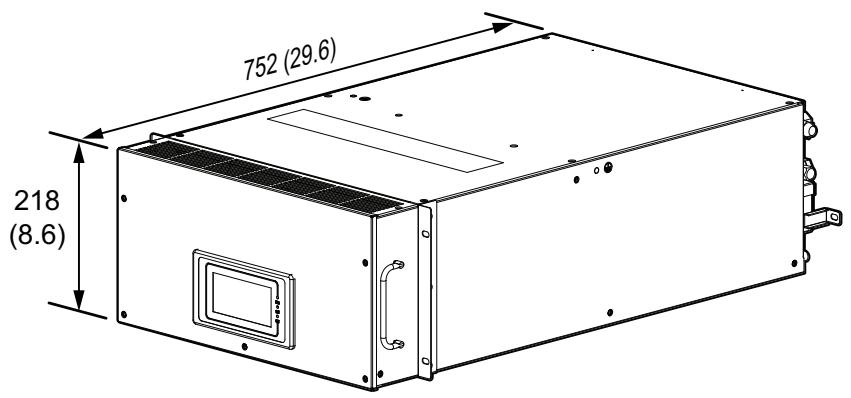
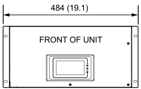
na6186-02a
NOTE: Display interface is optional.
Outdoor Units
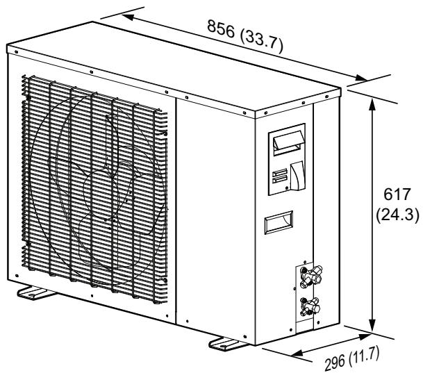
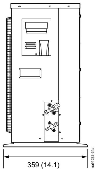
Weight
| Unit | Operating Weight – kg (lb) |
| Indoor unit | 26 kg (57.3 lb) |
| Outdoor unit | 48 kg (105.8 lb) |
Service Clearance
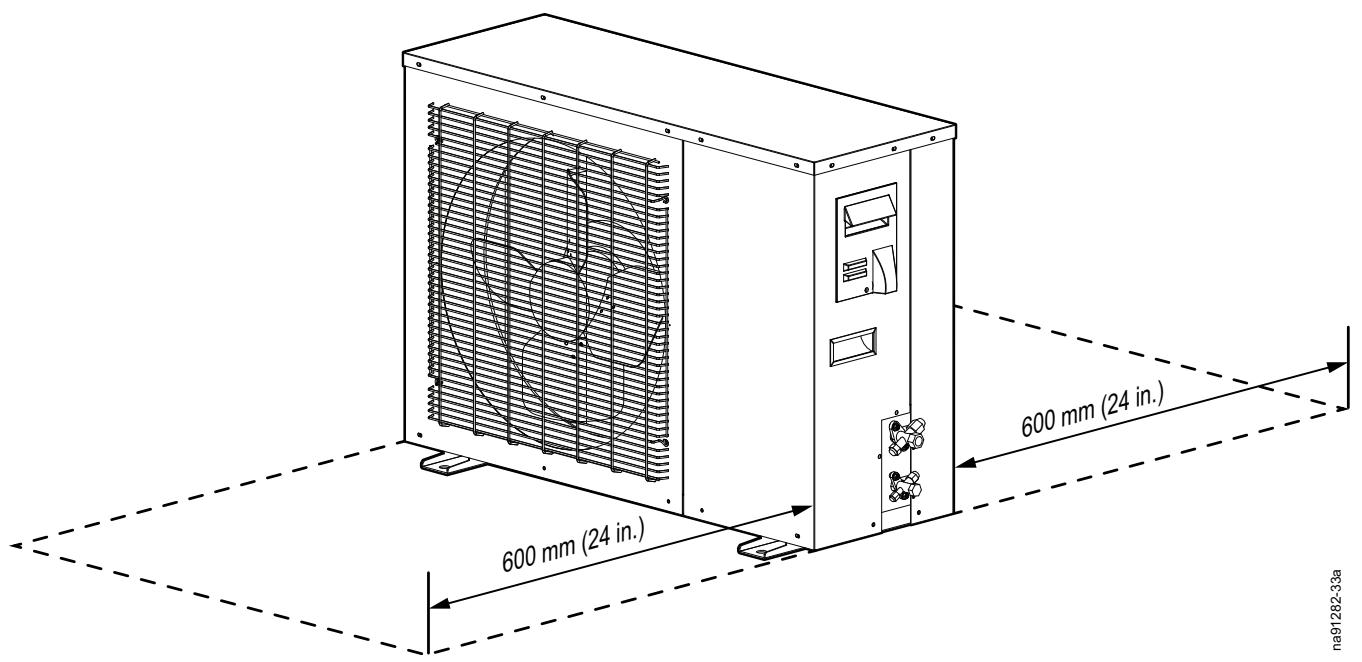
Airflow Clearance
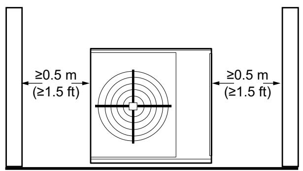
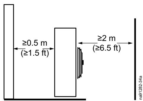
Access Locations
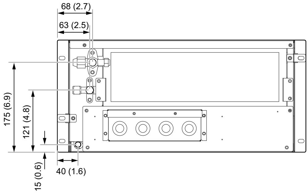
Indoor Unit
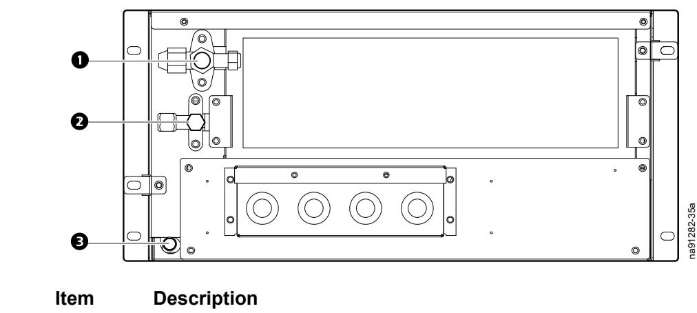
Suction line valve
Liquid line valve
3 Condensate drain line
Component Identification
Inventory
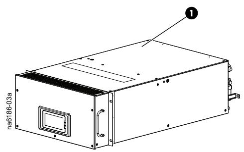
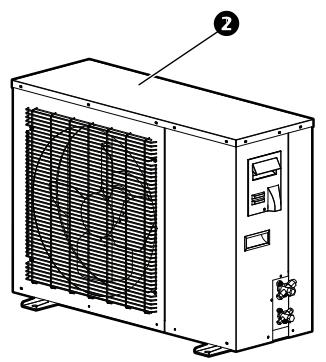
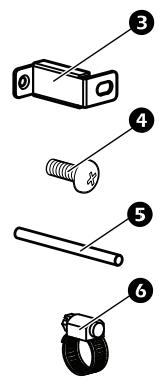
| Item | Description | Quantity |
| ① | Indoor unit | 1 |
| ② | Outdoor unit | 1 |
| ③ | Mounting bracket | 2 |
| ④ | M4x12 screw | 2 |
| ⑤ | Condensate drain hose | 1 |
| ⑥ | Hose clamp | 1 |
External Components
Indoor Unit
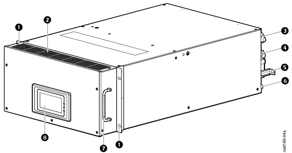
na6186-04a
| Item | Description | Item | Description |
| ① | Mounting flange | ⑤ | Mounting bracket (field installed) |
| ② | Grille | ⑥ | Condensate drain line |
| ③ | Suction line valve | ⑦ | Handle |
| ④ | Liquid line valve | ⑧ | Display interface (field installed) |
Outdoor Unit
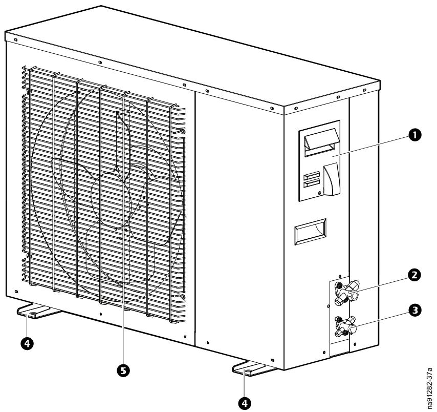
Item Description
Electrical panel access cover
Suction line valve
3 Liquid line valve
4 Mounting support
5 Fan protection grille
Internal Components
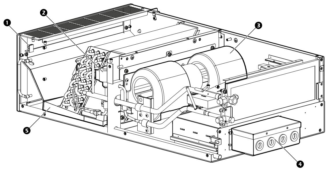
Indoor Unit
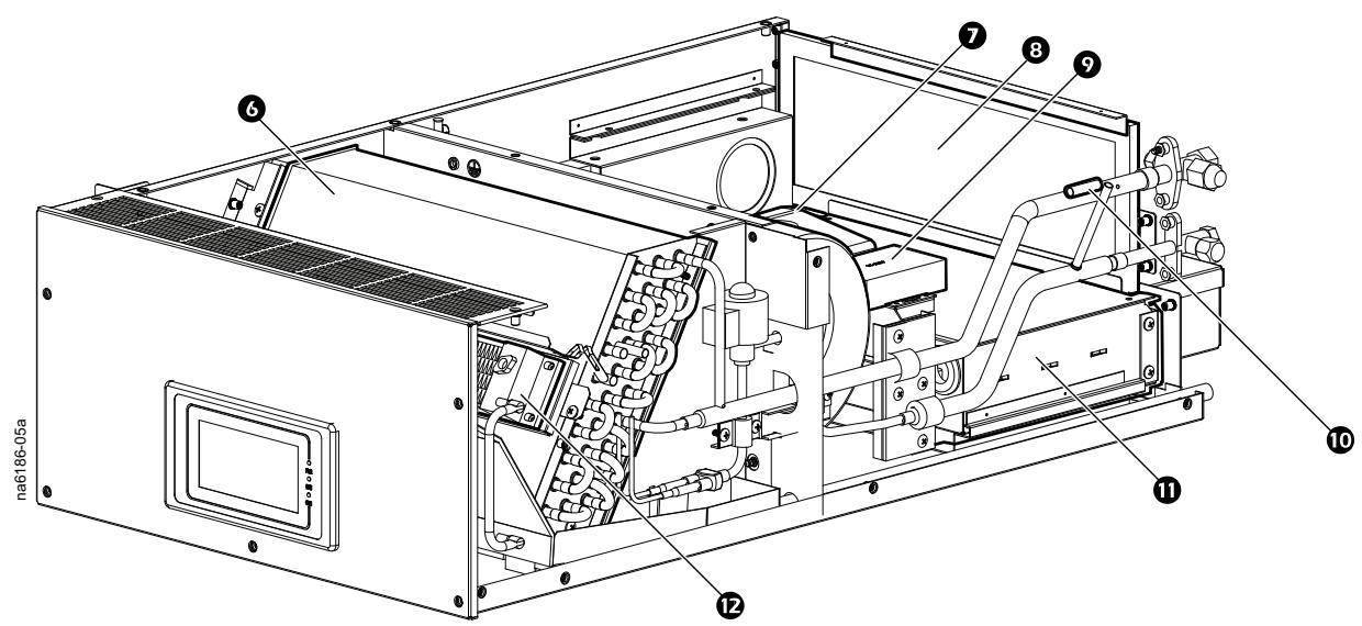
Item Description
Supply air temperature sensor
Electronic expansion valve (EXV)
3 Centrifugal fan
4 Connection access box
5 Condensate drain pan
Evaporative coil
Item Description
7 Temperature and humidity sensor
Air filter
Isolated data repeater
Suction line temperature sensor
1 Electrical box
Electric heater
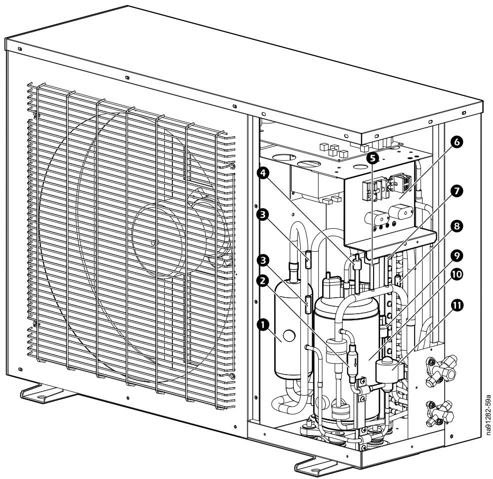
Outdoor Unit
| Item | Description | Item | Description |
| ① | Accumulator | ⑦ | High pressure sensor |
| ② | Filter | ⑧ | Discharge temperature sensor |
| ③ | Suction temperature sensor | ⑨ | Low pressure sensor |
| ④ | Service port | ⑩ | Compressor |
| ⑤ | High pressure switch | ⑪ | Electronic expansion valve (EXV) |
| ⑥ | Electrical panel |
Installation
Site Preparation
Follow these guidelines to prepare the site for installation.
- Moisture proof and insulate the room to ensure the normal functioning of the environmental control system inside the room.
- Use polyethylene film for the moisture barrier on the ceilings and walls.
- Use moisture-proof paints on the concrete walls and floor.
- Minimize the entry of the outdoor air into the IT space as outdoor air may increase heating, cooling, and humidification and dehumidification loads of the system. Maintain intake of outdoor air below 5% of the circulating air.
- Fully enclose all doors and windows with minimized gaps.
Incoming Power Supply Requirements
WARNING
ELECTRICAL HAZARD
- Electrical service must conform to local and national electrical codes and regulations.
The equipment must be grounded.
Failure to follow these instructions can result in death, serious injury, or equipment damage.
- The main power requirement is 200 - 240 ~V / 50 ~Hz .
- Ensure the electrical connection of the unit allows for the total load of the unit and its optional components. The difference between external static pressure of the unit and that of a standard unit may lead to changes in its input power and current. For the total input power and the total current, see the nameplate.
- The incoming power wire must have a circuit breaker of enough capacity with a contact opening distance of at least 3mm (0.11 in.).
- Provide each unit with an independent power supply with power supply cut-off and over-current protection devices.
- Before wiring, ensure the power supply conforms to the specified value on the nameplate.
- Keep the wires away from the cooling line and the moving parts of the compressor, fan, and motor.
Before You Start
The outdoor unit has been charged with refrigerant in the factory, and the indoor unit has been filled with a nitrogen holding charge. If you need to check the gas, do the following:
NOTE: Outdoor unit model ACRMD4KI-3 is not charged with refrigerant in the factory.
- Open the shutoff valve.
- Press the needle valve side of the service valve and check for gas ejection.
- Connect a pressure gauge to get an accurate reading.
Positioning Units
Outdoor Unit
| ▲CAUTION |
| HAZARD FROM SHARP EDGES |
| Many metal parts have sharp edges. Be careful and wear protective gloves and clothing when working around and inside the equipment. |
| Failure to follow these instructions can result in injury or equipment damage. |
| ▲CAUTION |
| DAMAGE TO EQUIPMENT OR PERSONNEL |
| Use concrete or a supporting frame to build a base for the unit. Allow for the floor strength, drainage treatment, duct, and wiring. Insufficient strength may cause the unit to drop resulting in injury or equipment damage. |
| Failure to follow these instructions can result in injury or equipment damage. |
| NOTICE |
| EQUIPMENT DAMAGE RISK |
| Install the unit in an area that is protected from adverse conditions such as an oil source (including engine oil), salt (in a marine region), and sulfide gases (near a hot spring or refinery). |
| Failure to follow these instructions can result in equipment damage. |
Select a location for the installation that adheres to the following guidelines:
- Does not take in hot air from the unit or another unit.
- Allows enough clearance space for maintenance.
- Has no obstacles in the air exhaust and draft ducts of the outdoor unit to stop airflow.
- Provides good ventilation to help the unit exchange heat.
- Has sufficient strength to bear the weight of the unit and its vibration during operation.
- Does not have dirt, oil, salt, or sulfide gases.
Is able to drain rainwater and defrost water. - Is not susceptible to flammable gas. If any flammable gas leaks and accumulates around the unit, an explosion may occur.
- Is not subject to direct blow of a strong breeze or typhoon. Install rainproof, snowproof, and sunproof equipment if possible.
The floor and wall may cause vibration and noises depending on the installation conditions. Adopt anti-vibration measures such as anti-vibration pad or bumper bracket.
Panel Removal
Indoor Unit
Electrical Box Access
- Remove the filter.
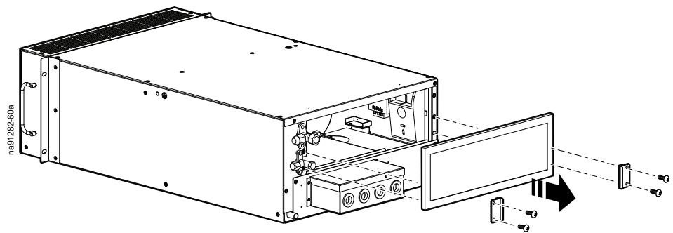
- Remove the electrical panel screws.
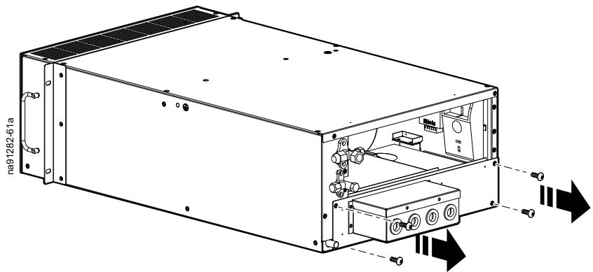
- Slide the electrical box out of the unit.
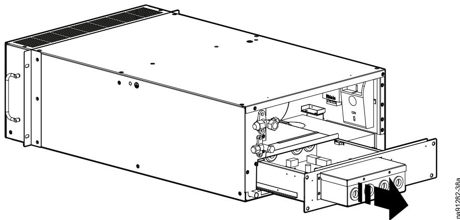
na91282-38a
Outdoor Unit
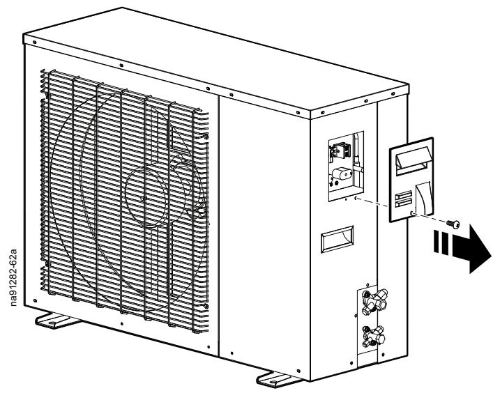
Electrical Panel Access
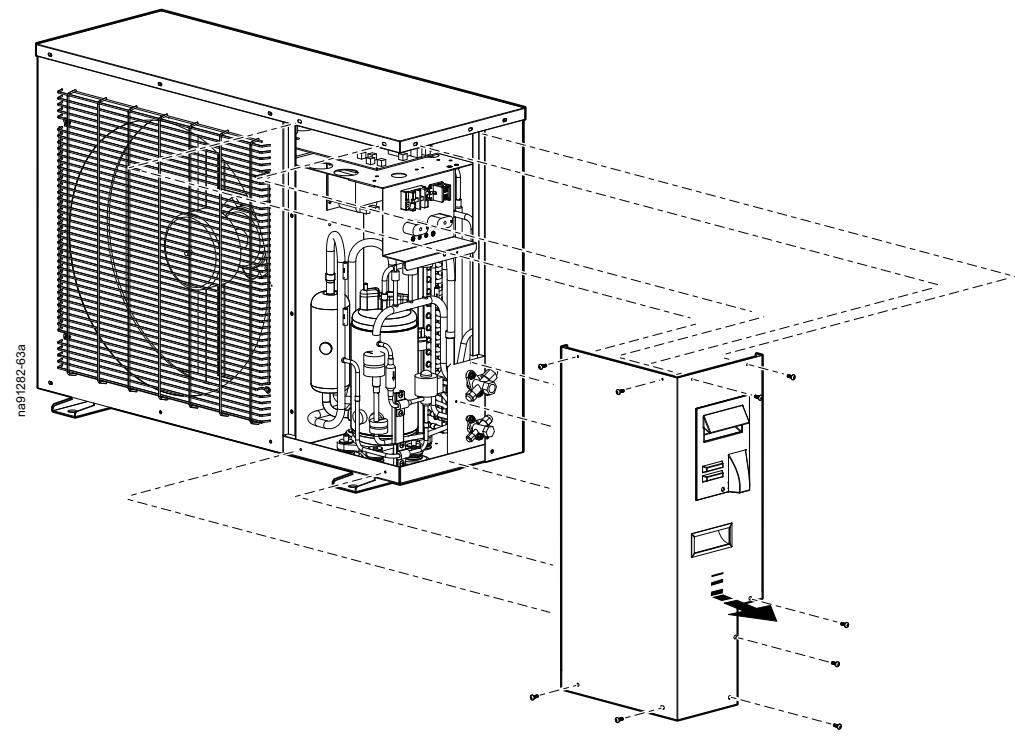
External Panel
Display Interface

See the installation sheet provided with the display interface for installation instructions.
Mechanical Connections
Installing the Indoor Unit in the Rack
The air conditioner is a cabinet refrigeration product that is installed in the standard cabinet of a machine room.
NOTE: Some components not shown for easier viewing.
- Install the optional rail kit in the cabinet where the unit is to be installed.

See the installation instructions in the rail kit.
- Slide the cooling unit into the rack on the rails.
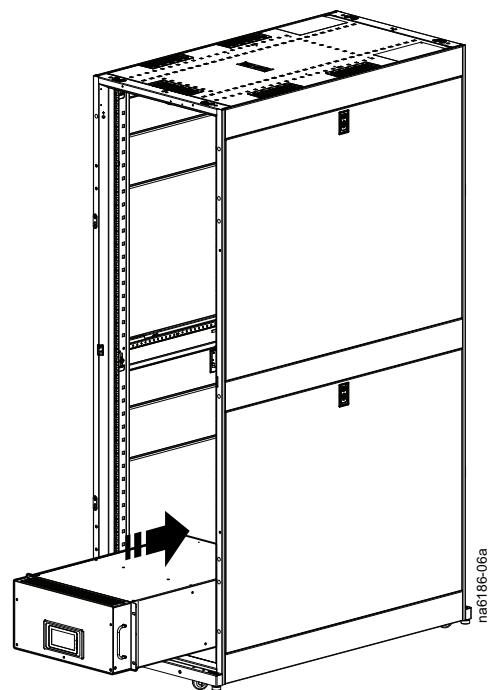
- Attach the front mounting flanges to the vertical mounting rails in the rack with the cage nuts and washers provided with the rack.
- Attach the rear of the unit to the vertical mounting rails with the supplied mounting brackets and the cage nuts and washers provided with the rack.
NOTE: These may not be necessary to support the unit if the rail kit is installed.
Installing the Outdoor Unit
CAUTION
SHARP EDGES
Do not touch the fins of the heat exchanger with bare hands.
Failure to follow these instructions can result in injury or equipment damage.
When installing the outdoor unit, follow these guidelines:
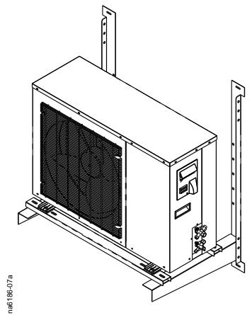
Concrete or a supporting frame should be used to build a base for the unit. When building the base, allow for the floor strength, drainage treatment (drainage water will outflow from the unit when it is in operation), and duct and wiring. Insufficient strength may cause the unit to fall.
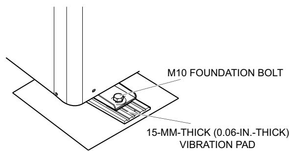
- The outdoor unit should be attached to the frame with M10 bolts at each corner of the mounting base of the outdoor unit.
- Vibrations and noise from the unit may be transmitted to the structure when it is in operation. Use anti-vibration pads or a similar measure to prevent transmission of vibrations and noise.
Piping Kit Application
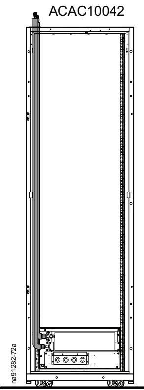
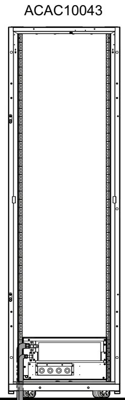
Three piping kits are available as options for use with the cooling unit:
- ACAC10042: Top piping
- ACAC10043: Bottom piping under the raised floor
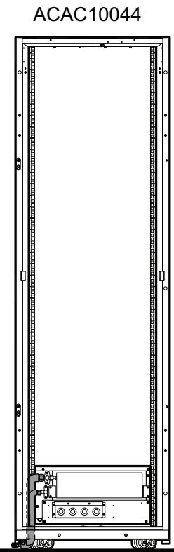
- ACAC10044: Bottom piping under the rack
Refrigerant Piping
Piping Connection
The maximum equivalent piping length between the indoor and outdoor units is 20 m (65.6 ft). The maximum vertical difference for the outdoor unit above or below the indoor unit is 5 m (16.4 ft). The table below outlines pipe sizes for field piping.
| Tube | Size |
| Liquid line | Ø9.52 mm (3/8 in.) |
| Gas line | Ø12.7 mm (1/2 in.) |
| Refrigerant R410A piping (minimum thickness) | 0.8 mm (0.03 in.) |
The minimum thickness of the piping specified in the instructions is based on drawn tube of copper and copper alloys (GB/T1527-2006). The thickness and material of pipes used must be able to withstand a pressure of 4.15 MPa (602 psi) in accordance with applicable laws.
If the unit is in an environment of severe corrosion, increase the thickness of the pipe by at least 0.2mm (0.008 in.).
If the piping has a reduced thickness from bending and tensioning, increase its wall thickness accordingly.
Refer to the sizes in the table for processing the bell mouth of copper piping.
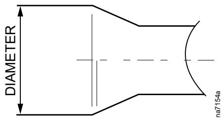
| OD | OD Size | |
| Metric | British | R410A |
| Ø6.35 mm | 1/4 in. | 9.1 mm (0.36 in.) |
| Ø9.52 mm | 3/8 in. | 13.2 mm (0.52 in.) |
| Ø12.70 mm | 1/2 in. | 16.6 mm (0.65 in.) |
| Ø15.88 mm | 5/8 in. | 19.7 mm (0.78 in.) |
| Ø19.05 mm | 3/4 in. | 24.0 mm (0.94 in.) |
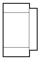
See the table for the corresponding flare nut specifications.
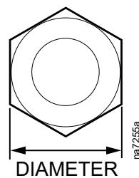
| OD | OD Size | |
| Metric | British | |
| Ø 6.35 mm | 1/4 in. | 17.0 |
| Ø 9.52 mm | 3/8 in. | 22.0 |
| Ø 12.70 mm | 1/2 in. | 24.0 |
| Ø 15.88 mm | 5/8 in. | 27.0 |
| Ø 19.05 mm | 3/4 in. | 36.0 |
Copper Pipe Connection
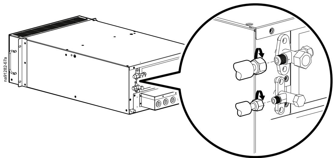
- Remove and keep the flare nuts and remove and discard the copper plugs from the liquid line and suction line connections.

- Connect the pipes from the selected pipe kit (ACAC10042, ACAC10043, or ACAC10044) to the liquid and suction lines.
NOTE: Make sure the piping does not inhibit removal of the electrical box.
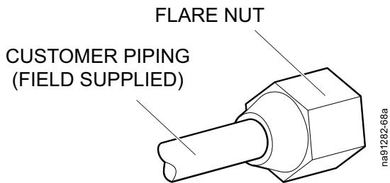
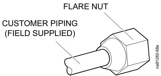
- Use a flaring tool to connect the customer piping (field supplied) to the flare nut.
NOTE: Make sure the flare nut is on the piping before using the flaring tool on the customer piping.
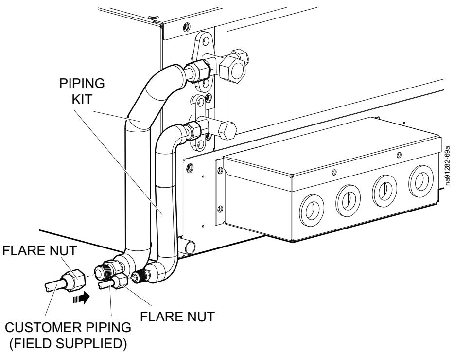
- Route the customer piping through the cabinet and connect the flare nuts to the customer-piping side of the pipe kit.
NOTE: Pipe kit ACAC10044 is shown.
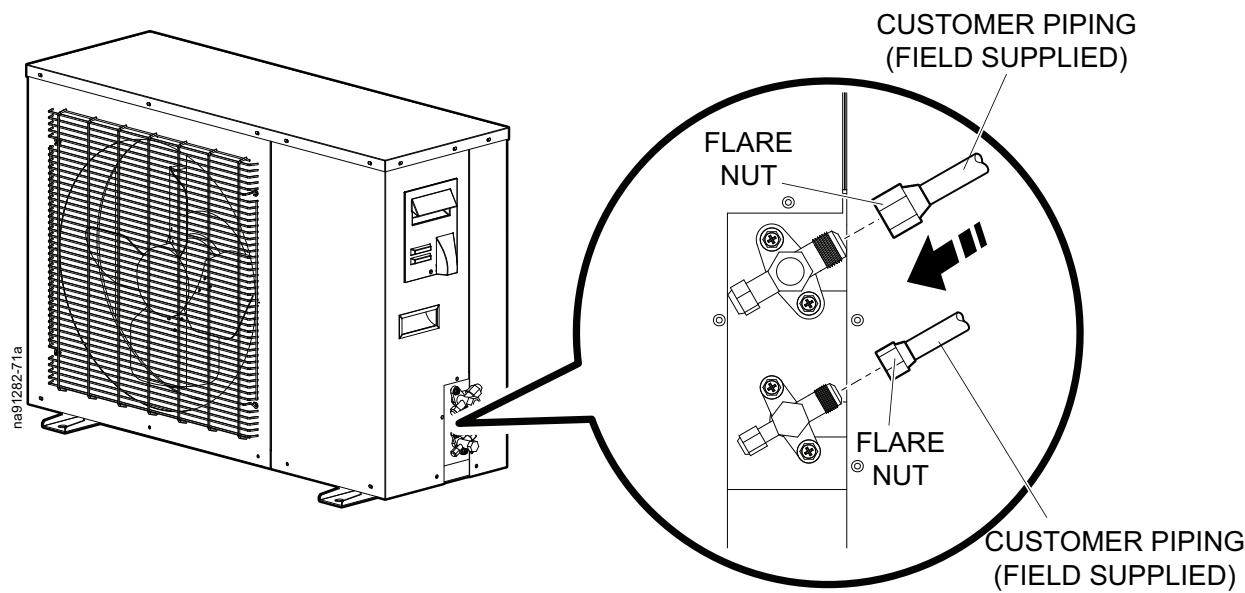
- Remove and keep the flare nuts and remove and discard the copper plugs from the liquid line and suction line connections.
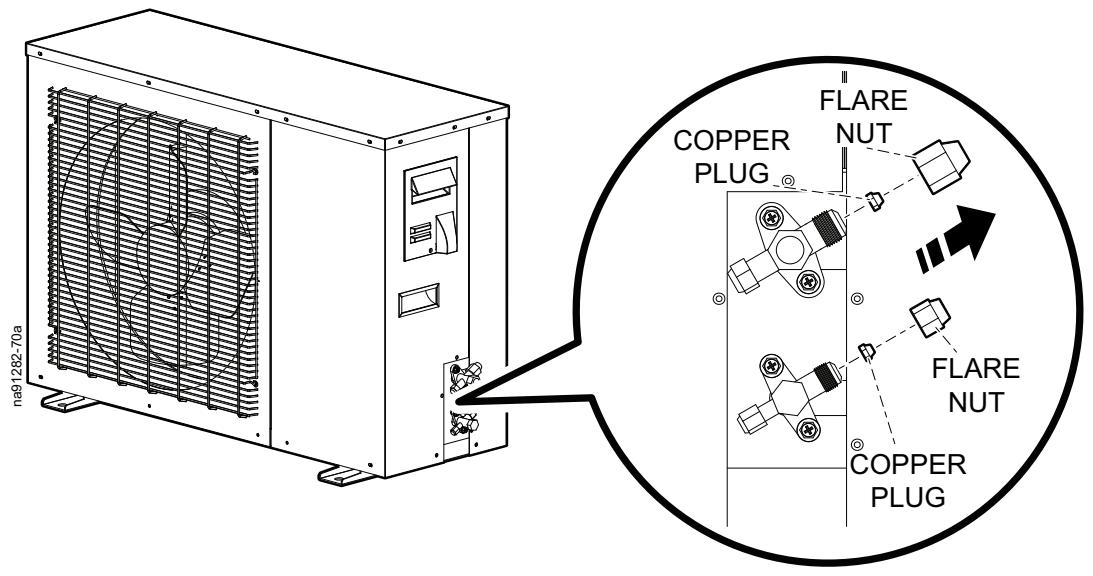
- Use a flaring tool to connect the customer piping (field supplied) to the flare nut.
NOTE: Make sure the flare nut is on the piping before using the flaring tool on the customer piping.
- Connect the flare nuts to the suction and liquid lines of the outdoor unit.
| OD | Tightening Torque | Tightening Angle |
| Ø6.35 mm(1/4 in.) | 14-18 N·m(10.33-13.28 ft-lb) | 60°-90° |
| Ø9.52 mm(3/8 in.) | 35-42 N·m(25.81-30.98 ft-lb) | 60°-90° |
| Ø12.7 mm(1/2 in.) | 50-57.5 N·m(36.88-42.41 ft-lb) | 30°-60° |
| Ø15.88 mm(5/8 in.) | 75-80 N·m(55.32-59.00 ft-lb) | 30°-60° |
| Ø19.05 mm(3/4 in.) | 100-140 N·m(73.76-103.26 ft-lb) | 20°-35° |
Brazing Copper Pipes
- Use a neutral flame to braze and control the ratio of oxygen to acetylene (O_2: C_2H_2 = 1.0 - 1.2) . Heat the base metal 20 - 25mm (0.78-0.98 in.) from the flame core given that the highest temperature is 2 - 3mm (0.7-0.11 in.) from the flame core (for reference only).
- Fill the copper pipe with nitrogen to eliminate air. An oxide film may lead to blockage of the expansion valve, filter, or other system components.
- Maintain the flow of nitrogen at 10–20 l (2.64–5.28 gal) per minute with a pressure regulating valve.
- Fill with nitrogen until the pipe is completely cooled down.
Insulating Refrigerant Pipes
Insulate the refrigerant pipes with closed cell foam insulation of sufficient thickness to cover the liquid pipe and the suction line. Improper insulation materials or installation methods may cause condensation to drip from the refrigerant pipes.
Drain Connection
- Attach the condensate drain hose to the drain connection of the unit with the hose clamp.

- Route the condensate drain hose out of the unit or connect it to the condensate drain pump.

See the condensate drain pump Installation Sheet.
Electrical Connections
▲▲DANGER
HAZARD OF ELECTRIC SHOCK, EXPLOSION, OR ARC FLASH
- Apply appropriate personal protective equipment (PPE) and follow safe electrical work practices.
This equipment must be installed and serviced by qualified personnel only. - Turn off all power supplying this equipment before working on or inside the equipment.
- Replace all devices, doors, and covers before turning on power to this equipment.
Failure to follow these instructions will result in death or serious injury.
▲▲DANGER
ELECTRICAL HAZARD
Overcurrent protection for all incoming power feeds must be provided by the customer. See unit nameplate for equipment ratings.
Failure to follow these instructions will result in death or serious injury.
WARNING
ELECTRICAL HAZARD
- Electrical service must conform to local and national electrical codes and regulations.
The equipment must be grounded.
Failure to follow these instructions can result in death, serious injury, or equipment damage.
WARNING
ELECTRICAL FIRE HAZARD
Use copper conductor wiring only.
Failure to follow these instructions can result in death, serious injury, or equipment damage.
The following electrical connections are required in the field:
- Power connection of the indoor unit (H05VV-F 3 x 1.0 mm² cable)
Power connection of the outdoor unit (H05VV-F 3 x 1.5 mm² cable) - Communication lines between the indoor and outdoor units (PLTC 2 x 0.5 mm² cable)
NOTE: A and B need to be distinguished when connecting.
Remote monitoring line of the unit
Before connecting the circuit, determine the input power voltage with a voltmeter, and turn the power off. Use PVC insulated copper wires or rubber insulated copper wires for the connecting wires of the indoor and outdoor units. The cross-sectional area must meet the maximum requirements for load of the unit and its components. Secure all wiring: Connecting wires of the indoor and outdoor units must be fixed on clips.
Wire Cross-Section Ratings
| Wire Area | Maximum Current |
| 1.0 mm² | 8 A |
| 1.5 mm² | 11 A |
| 2.5 mm² | 15 A |
| 4 mm² | 20 A |
| 6 mm² | 25 A |
| 10 mm² | 35 A |
Do not connect the same power terminal with two wires of different diameters.
When connecting to the terminal block, use a needle-shaped terminal with an insulation sleeve. Ensure the terminal connection to the wires is acceptable.
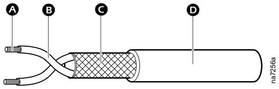
Item Description
Wires (cross copper wires of over 0.5mm^2
Insulating material
Shielding layer (requires more than 95% shielding effectiveness)
Outer layer protection (PVC)
Connection Interface
Connection interfaces include the total power input interface and the remote communication interface of the unit.
Indoor Unit

See the installation sheets provided with the accessories for more information.
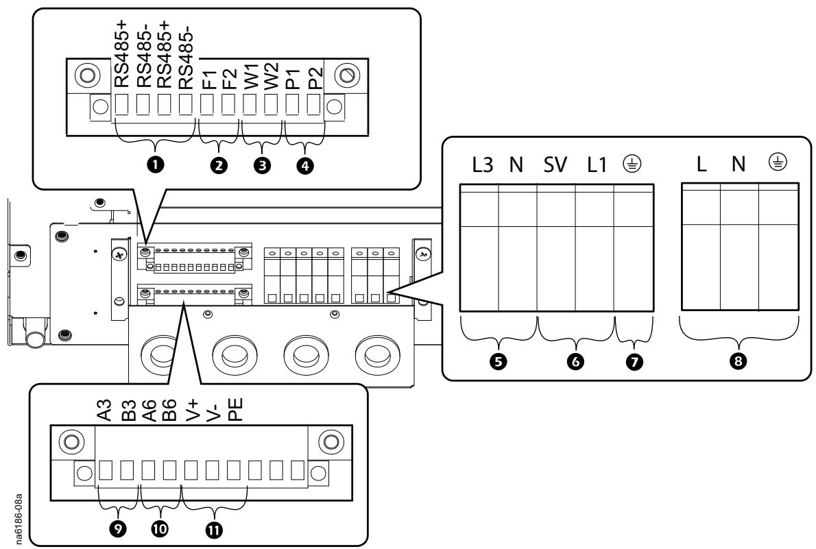
Item
1 Controller communication connections (RS485+, RS485-, RS485+, RS485-)
2 Fire/smoke alarm connection (F1, F2)
3 Leak sensor connection (W1, W2)
4 Condensate drain pump communication connection (P1, P2)
5 Condensate drain pump power supply connection (L3, N)
Low temperature kit connection
- Solenoid valve (SV)
High pressure control and heater (L1)
Item
Description
7
Ground (GND)
8
Power supply connection (L, N, GND)
9
Communication connection to the outdoor unit (A3, B3)
10
Display interface connection (A6, B6)
11
24-VDC power supply (V^+,V^-,PE)
- Remove the cover from the connections box.
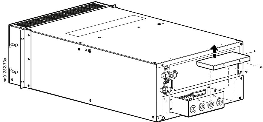
- Remove the communication position connectors from the electrical box to make connections easier.

- Route the power connections through the cable strain reliefs and make the connections in the unit.
- Route the communication connections through the cable strain reliefs and make the connections to the position connectors.
- Replace the communication position connectors.
- Replace the cover.
Outdoor Unit
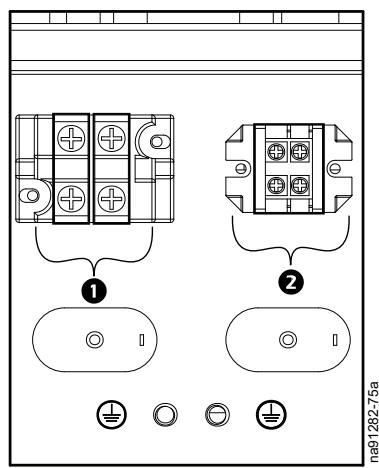
Item Description
Power supply connection (L, N, GND)
2 Communication connection to indoor unit (Ain, Bin)
- Remove the electrical panel cover.

See Panel Removal, page 26.
- Route cables through the cable strain reliefs and make the unit connections.
- Replace the electrical panel cover.
Charging the Refrigeration System
NOTICE
DAMAGE TO EQUIPMENT
Follow the procedures and tables outlined in this manual to charge the refrigerant if the piping exceeds the standard length.
Failure to follow these instructions can result in equipment damage.
Indoor and outdoor units are all provided with service valves. Connect the service valves to pipes for immediate system leak detection, vacuum pumping, and refrigerant filling procedures.
NOTE: Indoor units and outdoor unit model ACRMD4KI-3 are not pre-charged with refrigerant in the factory.
Leak Detection
Method One
- Fill the service valve with nitrogen to increase pressure to 2.8 MPa (406 psi) and 4.15 MPa (601 psi) for refrigerant R410A.
- Apply soapy water at the connecting joints or welding joints of pipes for leak detection.
- Repair leak sources and maintain the pressure for more than six hours to ensure that the pressure is not decreased.
- The low side of the compound gauge cannot be connected to the system.
Method Two
- Fill with the refrigerant and stop when the pressure gauge indicates 0.3MPa (43 psi).
- Fill with nitrogen and stop when the pressure gauge indicates 2.8 MPa (406 psi) and 4.15 MPa (601 psi) for refrigerant R410A.
- Use an HFC electronic leak detector to detect the leak. Use the bubble gas leak testing method.
Vacuum Pumping
- Exhaust the high pressure nitrogen in the system.
- Connect the three flexible pipes of the compound pressure gauge to the corresponding joints of the service valve and the vacuum pump.
- Start the vacuum pump and maintain the pressure inside the system below 650Pa (0.09 psi). Do not start the unit until the pipeline for vacuum pumping is turned off.
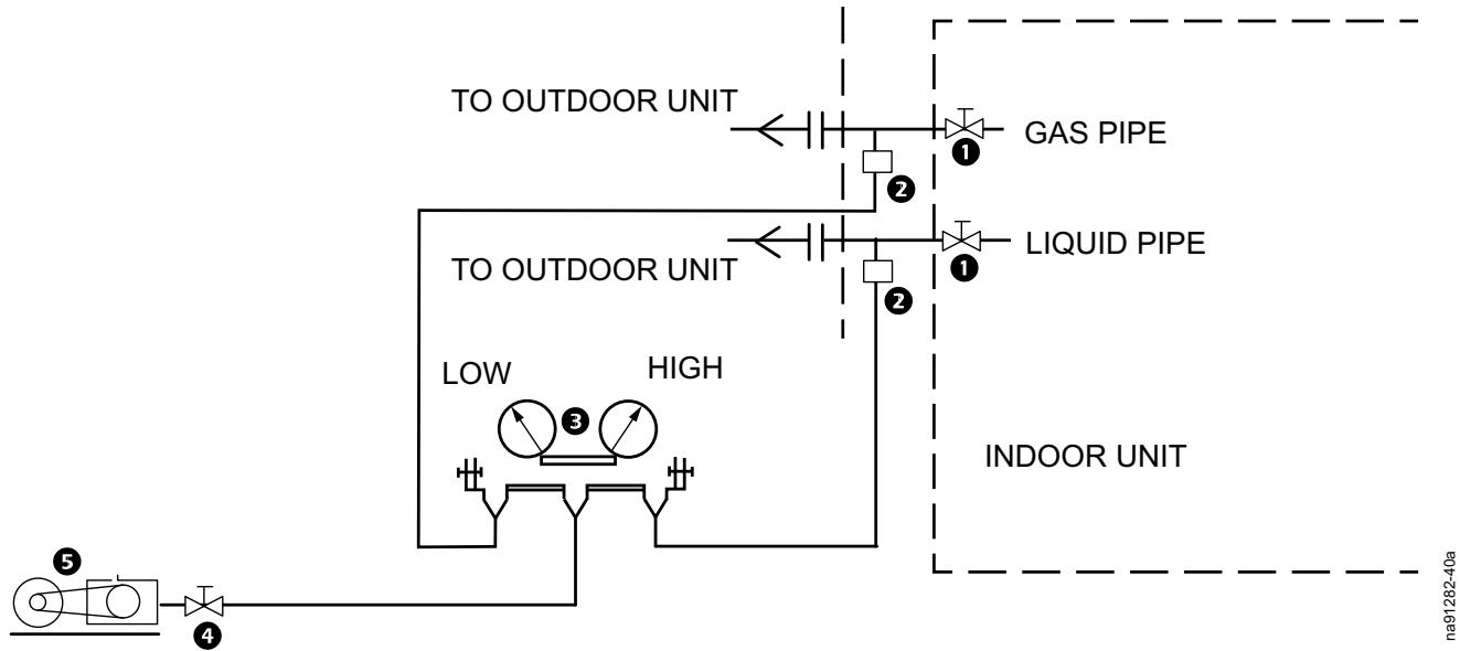
| Item | Description |
| ① | Ball valve |
| ② | Service port |
| ③ | Compound pressure gauge |
| ④ | Check valve |
| ⑤ | Vacuum pump |
Calculating the Refrigerant Charge
When leaving the factory, the outdoor units that have been filled with refrigerant in the factory have enough refrigerant required to cover 5 m (49 ft) of pipe. If the actual length of the pipe exceeds 5 m (49 ft), add more refrigerant for the additional length. Outdoor unit model ACRMD4KI-3 needs to be charged with 1.65 kg (3.64 lb) of R410A refrigerant for the initial 5 m (49 ft).
| Liquid Pipe Specifications – mm | R410A Refrigerant – g/m (lb/ft) | Actual Pipe Length |
| Ø22.23 | 350 (0.24) | L1 |
| Ø19.05 | 260 (0.17) | L2 |
| Ø15.88 | 180 (0.12) | L3 |
| Ø12.7 | 120 (0.08) | L4 |
| Ø9.52 | 70 (0.05) | L5 |
| Ø6.35 | 45 (0.03) | L6 |
The refrigerant to be added is calculated on the basis of the length and thickness of the lengthened pipe. The formula is: refrigerant to be added (kg) = 0.35 × L1 + 0.26 × L2 + 0.18 × L3 + 0.12 × L4 + 0.07 × L5 + 0.045 × L6 .
If the calculated result is less than 0.1kg , round it to 0.1kg . For example, if the calculated result is 28.62kg , then add 28.7kg as the charge amount.
Charging the Refrigerant
- Open the gas and liquid valves of the indoor and outdoor units.
- If the filling tank for R410A does not have siphons, invert it.
- Measure the filling amount with an electronic scale to prevent excessive filling.
Fill the gas pipe and the liquid pipe with liquid refrigerant at the same time. If the pressure is too large to fill the refrigerant, fill the refrigerant with a compressor during the test run.
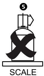
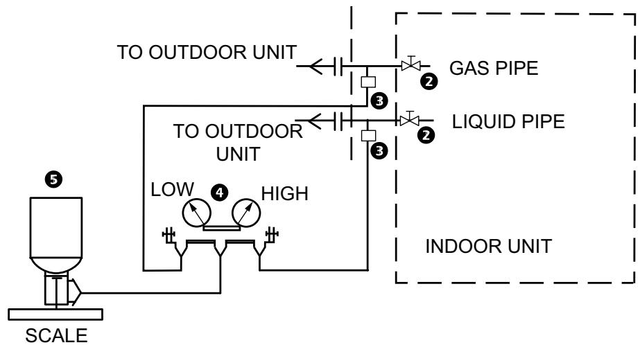
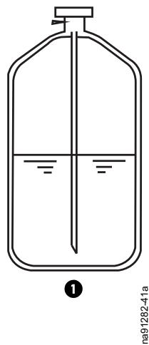
| Item | Description |
| ① | Cylinder with siphon |
| ② | Ball valve |
| ③ | Service port |
| ④ | Compound pressure gauge |
| ⑤ | Refrigerant tank |
Commissioning
After installation, verify that all components are working properly and the equipment is ready to begin operation.
Start-Up Inspection Checklist
The start-up inspection ensures that the equipment is operating properly after the initial start-up. This inspection verifies that all modes of operation are working correctly and the cooling unit is ready for normal operation.
Ensure that
The power core model of the outdoor and indoor units is correct.
The fan and motor of the indoor unit are working normally.
The fan and motor of the outdoor unit are working normally.
□ Communication lines are correctly connected.
The condensate pipe of the indoor unit is unblocked and the water seal installation is correct.
The equipment is properly grounded and insulation is correct (10 megohm).
The indoor and outdoor units have power supply in line with the nameplate, and the input voltage is not too high or too low.
The system has no leaks.
The main menu shows no fault after the unit is powered on.
Parameters on the manual operator are correctly set.
After the unit is started, the safety device does not trip.
The air-out temperature of the unit is within its normal range.
The air-out or air-return speed of the unit is within its normal range.
The unit has no abnormal sound and its components have no abnormal vibration.
The unit can operate normally by setting the switch mode and its components work accordingly.
After a Long Shutdown
If the outdoor unit is restarted after a long shutdown, energize it for at least 8 hours before restarting the compressor.
Electrical Inspection Checklist
▲▲DANGER
HAZARD OF ELECTRIC SHOCK, EXPLOSION, OR ARC FLASH
- Apply appropriate personal protective equipment (PPE) and follow safe electrical work practices.
This equipment must be installed and serviced by qualified personnel only. - Turn off all power supplying this equipment before working on or inside the equipment.
- Replace all devices, doors, and covers before turning on power to this equipment.
Failure to follow these instructions will result in death or serious injury.
WARNING
ELECTRICAL HAZARD
- Electrical service must conform to local and national electrical codes and regulations.
- The equipment must be grounded.
Failure to follow these instructions can result in death, serious injury, or equipment damage.
The electrical inspection verifies that all electrical connections are secure and correct and that the equipment is properly grounded.
Ensure that
The power core model of the outdoor and indoor units is proper.
□ Incoming voltages match the phase and voltage rating on the nameplate.
Electrical wiring complies with local and national codes and regulations.
The equipment is properly grounded and insulation is correct (10 megohm).
Electrical connections are tight, including contactors, terminal blocks, controllers, switches, relays, auxiliary devices, and field connections.
Circuit breakers are correct and securely attached to the DIN rail.
□ Communication lines are correctly connected.
Mechanical Inspection Checklist
CAUTION
HAZARD TO EQUIPMENT OR PERSONNEL
- The equipment is shipped from the factory with a nitrogen holding charge. Remove the nitrogen holding charge using the service ports located on the internal refrigerant piping.
- Improperly installed piping may result in improper operation and possible damage to the cooling unit or surrounding equipment.
Failure to follow these instructions can result in injury or equipment damage.
The mechanical inspection verifies that all mechanical components and connections are secure and tight and ready for start-up.
Ensure that
Clearance space around the unit is appropriate.
The fan and motor of the indoor unit are working normally.
The fan and motor of the outdoor unit are working normally.
The units are placed upright and fasteners used for installation are locked.
Pipes connecting the indoor and outdoor units are installed.
The drain pipe of the indoor unit is connected.
The condensate pipe of the indoor unit is unblocked and the water seal installation is correct.
All copper pipe joints are fastened.
The system has no leaks.
Fasteners for transport are removed.
Transport materials, structure materials, and tools inside or around the equipment are removed.
Operation
Using the Display
| Main Interface | ||||||
| Description | Screen | |||||
| Press the buttons on the Main Interface screen to access the following functions: • Alarm • ON/OFF • Input/Output (Operating Parameters) • Setpoint • User • Maintenance • Manufacturer | Air outlet temperature 0.0°C Air return temperature 0.0°C Air return humidity 0.0°C Operating mode Refrigeration/cooling | |||||
| ON/OFF | Input/Output | Setpoint | User | Mainten ance | Manufac turer | |
| Turning the Unit ON/OFF | ||
| Description | Screen | |
| Path: Main Interface > ON/OFF | 2019-03-20 16:11 | |
| ON OFF V1 Press the appropriate button to turn the unit on or off. | ||
| Operating Parameters-IDU Controller | ||
| Description | Screen | |
| Path: Main Interface > Input/Output > IDU Controller Operating Parameters | 2019-03-20 16:11 | |
| IDU Controller Operating Parameters | ODU Controller Operating Parameters | |
| Historical Data | Historical Alarms | |
| This screen provides information about the A01-EC fan and the IDU expansion valve steps. | 2019-03-20 16:11 | |
| A01-EC fan 0.0 V IDU expansion valve steps 0 | I1 | |
| Digital input:ON-No alarmOFF-Alarm | 2019-03-2016:11 | |
| Digital inputFire alarm / Remote ON/OFF ONHigh level switch of pump ONWater on the floor ON | ||
| Temperature and humidity parameters | 2019-03-2016:11 | |
| Air out temperature °CCoil Inlet temperature °CCoil outlet temperature °CCoil return temperature °CCoil return humidity | ||
| Parameters for alarms, pump, heater, fan, and low temperature kit | 2019-03-2016:11 | |
| Digital inputSerious alarm ONCommon alarm ONCondensation pump ONPTC heater ONIDU fan ONSV of low temperature kit ON | ||
| Fan and compressor run time | 2019-03-2016:11 | |
| Main fan 0.0 h#1 Compressor runtimes 0.0 h | ||
| Operating Parameters-ODU Controller | ||
| Description | Screen | |
| Path: Main Interface > Input/Output > ODU Controller Operating Parameters | 2019-03-20 16:11 | |
| IDU Controller Operating Parameters | ODU Controller Operating Parameters | |
| Historical Data | Historical Alarms | |
| Temperature parameters | 2019-03-20 16:11 | |
| #1 ODU parameter Operation frequency 0 Hz Ambient temperature 0.0°C Suction temperature 0.0°C Exhaust temperature 0.0°C System low pressure 0.0 Bar System high pressure 0.0 Bar | A10 A10 A10 A10 A10 A10 A10 A10 A10 A10 A10 A10 A10 A10 A10 A10 A10 A10 A10 A10 A10 A10 A10 A10 A10 A10 | |
| Operating Parameters-Historical Data | ||
| Description | Screen | |
| Path: Main Interface > Input/Output > Historical Data | 2019-03-20 16:11 | |
| IDU Controller Operating Parameters | ODU Controller Operating Parameters | |
| Historical Data | Historical Alarms | |
| Historical Humidity Data | ||
| Historical Data | ||
| 100 | ||
| 75 | ||
| 50 | ||
| 25 | ||
| 0 | ||
| 9:28 | 9:40 9:52 10:04 10:16 10:28 | |
| 2019-03-20 | 2019-03-20 2019-03-20 2019-03-20 2019-03-20 | |
| Operating Parameters-Historical Alarms | |||
| Description | Screen | ||
| Path: Main Interface > Input/Output > Historical Alarms | 2019-03-20 16:11 | ||
| IDU Controller Operating Parameters | ODU Controller Operating Parameters | ||
| Historical Data | Historical Alarms | ||
| Path: Main Interface > Input/Output > Historical Alarms > Alarm Press and hold Clear Alarm to clear alarms. | Historical Alarm | ||
| Time | Date | Alarm Message | |
| Setpoint | ||
| Description | Screen | |
| Path: Main Interface > Setpoint The password for the Setpoint screen is 1000. | 2019-03-20 16:11 | |
| Item Default | Air return temp.: 35°C Air outlet temp.: 22°C Minimum humidity: 15°C Maximum humidity: 80°C | |
| Air return temperature 35°C | ||
| Air outlet temperature 22°C | ||
| Minimum humidity 15°C | ||
| Maximum humidity 80°C | ||
| User | |||
| Description | Screen | ||
| Path: Main > User > User Password The default user password is 1000. Password error displays if a wrong password is entered. Enter the password within 5 seconds after the password error. | Please enter your password **** Password error. Confirm Cancel | ||
| Item | Default | Option | 2019-03-20 16:11 |
| Language | Chinese | English | PTC Heater YES Condensation pump YES P1 Unit OFF |
| PTC Heater | YES | NO | |
| Condensation pump | NO | YES | |
| Condensation pump alarm | UNIT OFF | ALARM | |
| User | ||||||
| Description | Screen | |||||
| Item | Default | Range | 2019-03-20 16:11 | |||
| Air outlet temperature limit | ||||||
| Air outlet temperature limit | Maximum 27°C | |||||
| Maximum | 27°C | 0-35°C | Minimum 13°C | P2 | ||
| Minimum | 13°C | 0-20°C | Air return temperature limit | |||
| Air return temperature limit | Maximum 42°C | |||||
| Maximum | 42°C | 0-50°C | Minimum 16°C | |||
| Minimum | 16°C | 0-35°C | ||||
| Item | Default | Range | 2019-03-20 16:11 | |||
| Air return temperature alarm | ||||||
| Air outlet temperature limit | High temperature 45°C | |||||
| High temperature | 45°C | 0-50°C | Return humidity alarm | |||
| Return humidity alarm | Low humidity 15% | |||||
| Low humidity | 15% | 0-95% | High humidity 95% | |||
| High humidity | 95% | 0-100% | Air outlet temperature alarm | |||
| Air outlet temperature alarm | Low temperature 8°C | |||||
| Low temperature | 8°C | 0-13°C | High temperature 32°C | |||
| High temperature | 32°C | 0-25°C | ||||
| Item | Default | Range | 2019-03-20 16:11 | |||
| BMS control YES | ||||||
| BMS control | YES | NO | Modbus address 0 | |||
| Modbus address | 0 | 0-255 | Comunication speed 9600 | |||
| Communication speed | 9600 | 4800/9600/19200 | New user password 0 | |||
| New user password | 1000 | 0-65535 | Touch Screen Sound ON/OFF | |||
| Press Date Time to show the date and time. Press Touch Screen Sound to turn the sound on or off. | ||||||
| Description | Screen | |||||
| Path: Main > Maintenance | 2019-03-20 16:11 | |||||
| IDU board version: SE(IDC_EN1.3 ODU board version: SE(IDC_EN1.3 HMI version: SE_HMIC_EN 1.3 | Touch Screen Sound ON/OFF | Alarm Sound ON/OFF | Reset Touch Screen | F1 | ||
| Outlet temperature off | 19°C | |||||
| Item | Default | Range | IDU board version | SE(IDC_EN 1.3 ODU board version | SE(IDC_EN 1.3 ODU board version | |
| Outlet temperature for unit off | 19°C | 14-24°C | HMI version | SE_HMIC_EN 1.3 | ||
| Select YES for manual operation. Select Manual and ON from the drop-down lists. | 2019-03-20 16:11 | |||||
| Manual operation | NO | |||||
| Serious alarm | Auto | OFF | ||||
| Common alarm | Auto | OFF | F2 | |||
| Condensation pump | Auto | OFF | ||||
| PTC heater | Auto | OFF | ||||
| IDU fan | Auto | OFF | ||||
| SV low temperature kit | Auto | OFF | ||||
| IDU maintenance information | 2019-03-20 16:11 | |||||
| IDU fan speed | Auto | 0.0V | ||||
| IDU EEV steps | Auto | 0 | F3 | |||
| IDU maintenance information | 2019-03-20 16:11 | |||||
| Modify run hours IDU fan hours reset | NO | |||||
| #1 Compressor hours reset | NO | F4 | ||||
| Threshold running hours alarm IDU fan | 0.0 h | |||||
| IDU maintenance information for temperature and humidity | 2019-03-20 16:11 | |||||
| Probe setting Air outlet temperature | 0.0°C | |||||
| Coil inlet temperature | 0.0°C | F5 | ||||
| Coil outlet temperature | 0.0°C | |||||
| Air return temperature | 0.0°C | |||||
| Air return humidity | 0.0% | |||||
| Press the appropriate buttons to clear and download alarm or date. | 2019-03-20 16:11 | |||||
| New maintenance password | 0 | |||||
| Clear History Alarm | Clear History Date | Download Alarm to U Disk | Download Date to U Disk | |||
| Manufacturer | ||||
| Description | Screen | |||
| Path: Main > Manufacturer Enter a new manufacturer password. | 2019-03-20 16:11 | |||
| Default value NO New manufacturer password 0 | ||||
| Configuration Management | Parameters Timing | |||
| Path: Main > Manufacturer > Configuration Management | 2019-03-20 16:11 | |||
| Item | Default | Option | BMS Network Standard D11 Function selection Fire/Smoke Condensation pump alarm NO Water on floor NO Maintenance alarm YES | |
| BMS Network | Standard | Custom | ||
| DI1 Function selection | Fire/Smoke | Remote | ||
| Condensation pump alarm | NO | YES | ||
| Water on floor | NO | YES | ||
| Maintenance alarm | YES | NO | ||
| Path: Main > Manufacturer > Parameters | 2019-03-20 16:11 | |||
| Item | Default | Maximum speed of EC/DC fan 0.0 V Minimum speed of EC/DC fan 0.0 V Failure speed of EC/DC fan 0.0 V Dehumidifying speed EC/DC fan 0.0 V | ||
| Maximum speed of EC/DC fan | 10 | |||
| Maximum speed of EC/DC fan | 10 | |||
| Failure speed of EC/DC fan | 10 | |||
| Dehumidifying speed of EC/DC fan | 5 | |||
| Path: Main > Manufacturer > Timing | 2019-03-20 16:11 | |||
| Item | Default | Delay time to stop fan 5 seconds Delay alarm low/high temperature30 seconds Delay alarm condensation pump 5 seconds Delay alarm output 10 seconds | ||
| Delay time to stop fan | 5 seconds | |||
| Delay alarm low/high temperature | 30 seconds | |||
| Delay alarm condensation pump | 5 seconds | |||
| Delay alarm output | 10 seconds | |||
Maintenance
Preventive Maintenance
▲▲DANGER
HAZARD OF ELECTRIC SHOCK, EXPLOSION, OR ARC FLASH
- Apply appropriate personal protective equipment (PPE) and follow safe electrical work practices.
This equipment must be installed and serviced by qualified personnel only. - Turn off all power supplying this equipment before working on or inside the equipment.
- Replace all devices, doors, and covers before turning on power to this equipment.
Failure to follow these instructions will result in death or serious injury.
WARNING
HAZARD TO EQUIPMENT OR PERSONNEL
All work must be performed by Schneider Electric qualified personnel.
Failure to follow these instructions can result in death, serious injury, or equipment damage.
Perform the following maintenance check list.
Prepared By:
Model Number:
Serial Number:
Date:
Electrical Maintenance
Perform visual inspection and processing of electrical connections.
| ☐ Perform a total electrical insulation test. Find the non-conforming contacts for processing. Disconnect the control switch or air switch during the test to avoid any damage to the control device from high voltage. | |
| ☐ Statically detect whether each contactor is pulled in flexibly without jamming. | |
| ☐ Remove dust from the electrical and control components with a brush or dry compressed air. | |
| ☐ Check for arcing or burn marks on the contacts. Replace the contactor if necessary. | |
| ☐ Fasten each electrical connection terminal. | |
| ☐ Check whether the quick connector is in good contact and replace the terminal if necessary. | |
| ☐ Check the appearance of the adapter and test its output voltage for the indoor and outdoor units. | |
| ☐ Check the output connection from the control interface board to each contactor and the input connection of the high and low voltage switches, and filter plug switch. Replace the plug terminal immediately if it is loose or has bad contacts. | |
| ☐ Replace the control fuse (or air switch), control board, and other electrical components if necessary. |
Control Maintenance
Perform visual inspection and simple function testing of the control segment for processing.
| □ | Check for obvious aging on the surface of the control interface board and the display control board. |
| □ | Remove the dust and dirt on the control components and control boards with a brush and an electronic deducting agent. |
| □ | Check and fasten the I/O plug interface of the control interface board, including the connection between the display control board and the control interface board and the connection between the control interface board and the temperature and humidity sensor board. |
| □ | Check the specifications and aging of the control wire and the power wire and replace if necessary. |
| □ | Check and calibrate the readings of the temperature and humidity sensor with an instrument of high measuring accuracy. Select relative humidity control as the humidity control mode. |
| □ | Clean the air filter net. Place on a hard surface and gently tap to remove heavy particles. If necessary, wash the filter with a neutral detergent in warm water and dry it before re-installation. |
| □ | Use a vacuum cleaner and a nylon brush to clean the dust and other debris on the surface of the heat exchanger. If a compressed air source is available, use the compressor to spray the dust off the surface. |
| □ | Regularly check the motor, impeller, and other components of the fan. If necessary, consult the manufacturer for more details. |
| □ | Before operating the unit, ensure the drainage pipe is not blocked. |
Worldwide Customer Support
Customer support for this or any other product is available at no charge in any of the following ways:
-
Visit the Schneider Electric Web site to access documents in the Schneider Electric Knowledge Base and to submit customer support requests.
-
www.schneider-electric.com (Corporate Headquarters)
Connect to localized Schneider Electric Web sites for specific countries, each of which provides customer support information.
- www.schneider-electric.com/support/
Global support searching Schneider Electric Knowledge Base and using esupport.
- Contact the Schneider Electric Customer Support Center by telephone or e-mail.
Local, country-specific centers: go to www.schneider-electric.com/support/contactwww.schneider-electric.com > Support > Operations around the world for contact information.
For information on how to obtain local customer support, contact the representative or other distributors from whom you purchased your product.
Schneider Electric (China) Co., Ltd Shanghai Pu Dong Branch 4F Building 9, No 3000 Long Dong Avenue, 201203
Pu Dong, Shanghai
People's Republic of China
www.schneider-electric.com
As standards, specifications, and design change from time to time, please ask for confirmation of the information given in this publication.