MODE D'EMPLOI E511S GPS EACHINE
natural_image
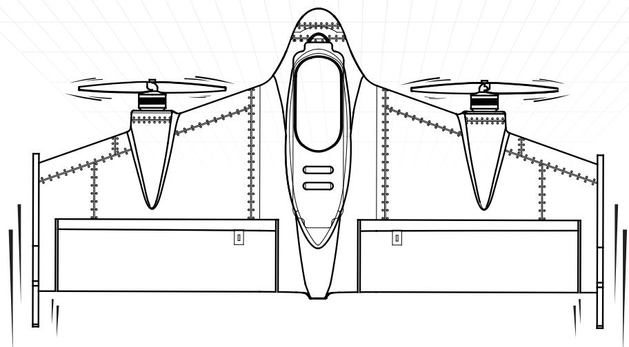
Technical line drawing of a flying aircraft with two propellers and control panels (no text or symbols)
Vertical Fixed Wing
Fly Over Infinity!
Product description
This product is a multi-function aircraft capable of vertical take-off and landing flights, one-touch automated transition design, differential control and a variety of flight modes so that you can even in the absence of complex mechanical devices and cumbersome software programming can Easily switch between multi-rotor and fixed-wing mode control, and it is equipped with the FPV system is allowing you to easily fly in the sky to fly, to bring you a different kind of flight experience.
Table of Contents
1.0 Know Your Aircraft 1
2.0 The main parameters 1
3.0 Product features 2
4.0 Flight Control Port Definition 2
5.0 Remote control introduction 3
5.0.1 Remote control panel function 3
5.0.2 Remote control battery installation 3
6.0 LED definition 4
7.0 Pre-Flight Preparation 4
7.0.1 Vertical tail mounting 4
7.0.2 FPV System Installation 5
7.0.3 Custom applique installation 5
7.0.4 Aircraft battery charging 6
7.0.5 Battery Installation 6
7.0.6 Propeller installation 6
7.0.7 Horizontal calibration - - - - - - - - - - - - - - - - - - 7
7.0.8 Unlock and lock 7
8.0 FPV System Operation Guide 8
9.0 Aircraft basic operation and control 9
9.0.1 Vertical flight mode 9
9.0.2 Horizontal flight mode 9
10.0 Flight Mode Description 10
11.0 Flight Environment 11
12.0 Troubleshooting 12
12.1 FPV Troubleshooting 12
13.0 FLYSKY Receiver (1)---- 12
13.1 FRSKY Receiver (2) 13
14.0 Parts List 13
1.0 Know Your Aircraft
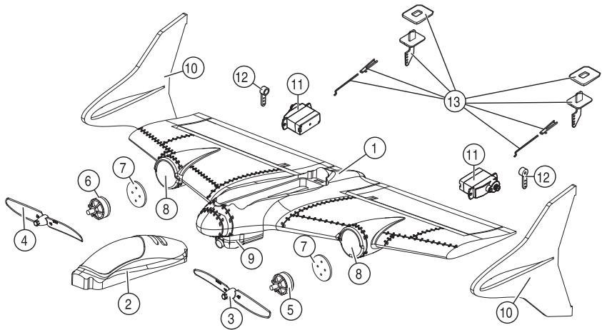
This product uses a new modular and plug-in design, improved product development, easy installation and maintenance, replacement and upgrading. The EPP body material, which makes the entire aircraft more lightweight and durable.
-
Body
-
Hatch cover
-
Forward rotation propeller
-
Reverse the propeller
-
Forward motor
-
Reverse motor
-
Motor Block
-
Motor installation location
-
FPV system components
-
Vertical tail
-
Servo
-
Rudder arm
-
Rocker arm assembly
2.0 The main parameters
Propeller: 5030 two-leaf self-locking paddle
Camera: Mini 7mm 1000TVL camera
Material: EPP
Motor: 1806 brushless motor 2300KV
Battery: 7.4V 600mAh 25C
Servo: 3.7g
Flight Difficulty: Average
Working environment temperature: -10 °C to +40 °C
Flight weight: 180g
Center of gravity: 125-135mm (measured forward from the trailing edge of the wing)
Wingspan: 500mm
Body size: 500 × 255 × 81mm (excluding vertical tail)


(180g)
3.0 Product features
● Supports three flight modes
● Support flight mode a key transition switch
● Support vertical take-off and landing and hand-throw takeoff
● With differential control, the flight response is more agile and faster
● Support a very small range take off and land flights EPP material, the body lighter and more durable.
● Support FPV flight, easy to enjoy the God perspective, Overlooking the earth.
● Support low-speed flight
● Support the size of the rudder switch

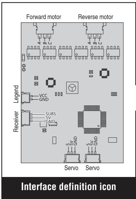
4.0 Flight Control Port Definition

natural_image
Technical line drawing of a mechanical or electrical component assembly (no text or symbols visible)
5.0 Remote control introduction
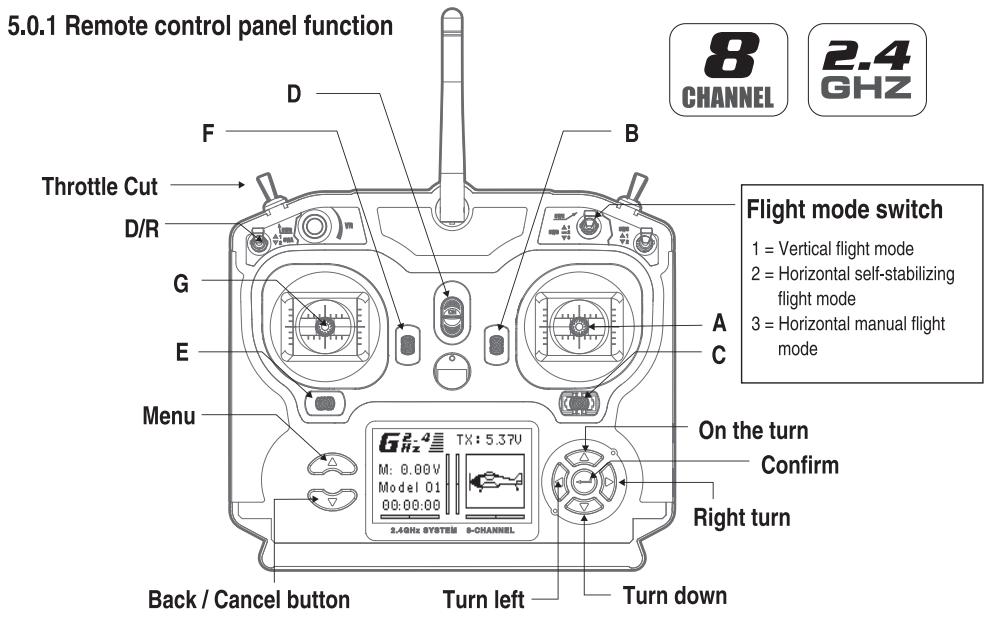

Tips:
CH5 used in a set of three switches to switch flight mode; Set CH6 on a two-stage switch to switch the size of the rudder;
| A | B | C | D | E | F | G |
| Model 1 | Aileron(Left/Right) Throttle(Up/Down) | Throttle Trim | Aileron Trim | ON/OFF Switch | Rudder Trim | Elevator Trim | Rudder(Left/Right) Elevator(Up/Down) |
| Model 2 | Aileron(Left/Right) Elevator(Up/Down) | Elevator Trim | Aileron Trim | ON/OFF Switch | Rudder Trim | Throttle Trim | Rudder(Left/Right) Throttle(Up/Down) |
5.0.2 Remote control battery installation

6.0 LED definition
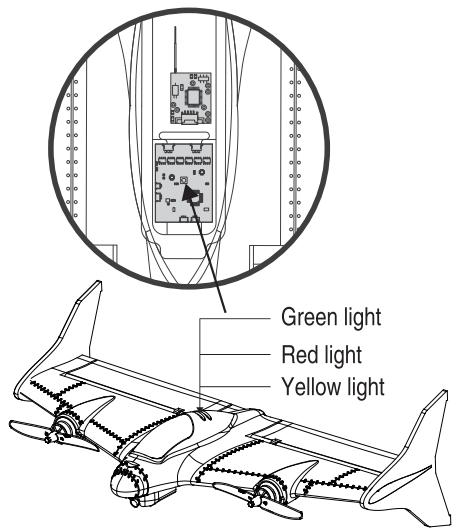
Aircraft indicator definition
Red light: vertical flight mode indication
Green light: horizontal self-propelled flight mode indication
● Yellow light: Horizontal manual mode indication
7.0 Pre-flight preparation
7.0.1 Vertical tail mounting: Remove the vertical tail from the fitting and attach it to the wing in the correct direction.

Note: First confirm the correct assembly direction and then hit the plastic.

natural_image
Technical line drawing of a mechanical component with labeled section A (no text or symbols beyond label)

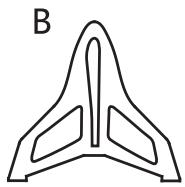
Vertical tail
Vertical tail interface
Vertical interface smear glue
7.0.2 FPV System Installation
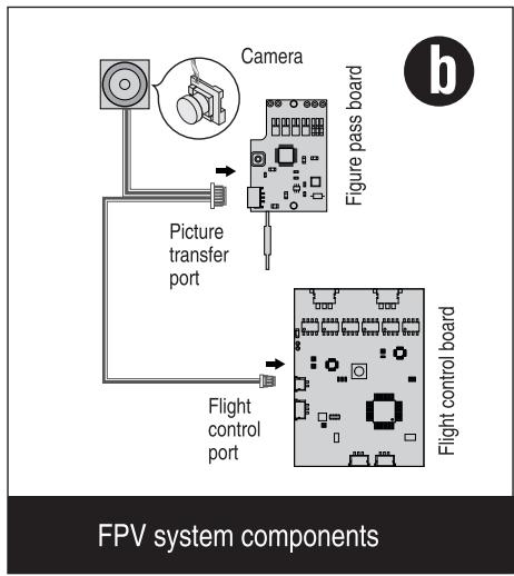
- Buy the FPV system components and install it in the aircraft's designated location (as shown in Figure a)
- Wiring Diagram (Refer to Figure b)

flowchart
graph TD
    A["Camera"] --> B["Figure pass board"]
    B --> C["Flight control board"]
    D["Picture transfer port"] --> C
    E["Flight control port"] --> C
    style A fill:#f9f,stroke:#333
    style B fill:#ccf,stroke:#333
    style C fill:#cfc,stroke:#333
    style D fill:#ffc,stroke:#333
    style E fill:#fcc,stroke:#333
7.0.3 Custom applique installation
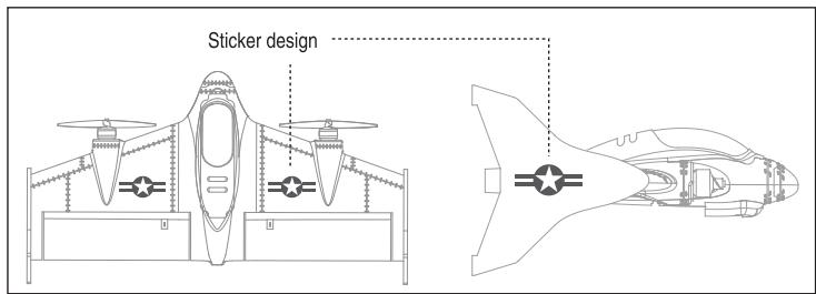
This product matching design with two styles of stickers, the user according to their own preferences paste.

7.0.4 Aircraft battery charging
Connect the charging cable to the USB port of the computer (or the USB interface with DV5V output), the red light on the charging cable will be on and the balanced charging port on the battery end will be connected to the balanced charging port of the charging cable, and the green light above the charging cable will flash. When the green light is full, turn on the green light. When the green light is on, recharge the battery for another 20 minutes to reach full power.

Tips: Please charge before use!

7.0.5 Battery Installation
Open the nacelle cover, remove the Velcro from the accessory, attach it to the battery and the battery compartment, and then attach the battery to the nacelle.

7.0.6 Propeller installation
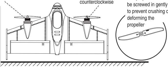
Install the propeller: pinch the motor with your left hand, pinch the small hat of the propeller with your right hand and align it with the motor shaft (Forward motor: turn the screw counterclockwise, turn the motor: screw the screw clockwise and tighten)

Tips:
Propeller installation has positive and negative requirements, the user needs the following method to install.
Reverse motor
Propeller screwed clockwise
7.0.7 Horizontal calibration
Calibration method
Placing the aircraft vertically on a horizontal ground first sets the throttle stick and pitch stick to the lowest position simultaneously to calibrate the aircraft. The status indicator on the aircraft side flashes three times in succession after calibration, and the calibration is successful after the flashing.

Tips: Before taking off the aircraft, be sure to place the aircraft on the water level to make sure that the aircraft will fly smoothly after takeoff. When the aircraft is hit or collided after the deviation, but also the same method of calibration.
The status light
flashes three times in
a row

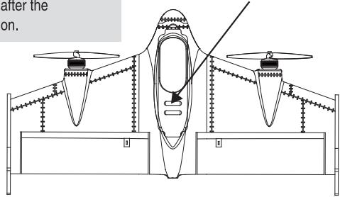
At the same time placed in
the lowest position
7.0.8 Unlock and lock
Use the throttle switch to unlock and lock, but also can play a role in preventing misuse
Unlock and lock method

8.0 FPV system operation guide
- Frequency (Offic.VHHz)
| CH1 | CH2 | CH3 | CH4 | CH5 | CH6 | CH7 | CH8 |
| 5658 | 5695 | 5732 | 5769 | 5806 | 5843 | 5880 | 5917 |
- Frequency switching mode. Short press the button in order to cycle
- Frequency instructions
CH1, the frequency indicator blue light (as shown on the right) flashes every 2 seconds; CH2 flashes 2 seconds every 2 seconds; CH3 flashes 3 seconds every 2 seconds; CH4 flashes 4 times every 2 seconds, followed by analogy.

9.0 Aircraft basic operation and control
Joystick operation mode
The product supports two main flight modes of vertical flight and horizontal flight. It is very important to understand the different control methods and responses in different modes. Please read the following carefully before the first flight.

Tips:
Due to its responsiveness, it is recommended to beginners to operate the rocker slowly and avoid drastically boosting the throttle. For horizontal flight, it is recommended to use a horizontal self-propelled mode.
9.0.1 Vertical flight mode
Throttle

Throttle up
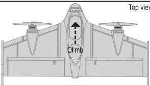
Top view

Throttle down

9.0.1 Vertical flight mode
Elevator
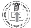
Elevator down
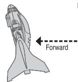
Left side view
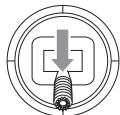
Elevator up
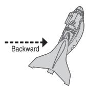
Left side view
Aileron
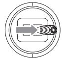
Aileron right
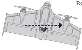
Top view
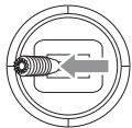
Aileron left
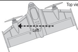
Top view
Rudder
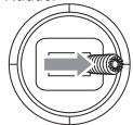
Rudder right


Rudder left
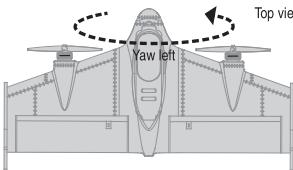
Top view

When flying outdoors, the vertical flight mode is only recommended for use as a vertical takeoff and landing function, otherwise there is a risk of crash when improper operation occurs!
9.0.2 Horizontal flight mode
Throttle

Throttle up
Left side view

Left side view

Throttle down

Left side view
Elevator
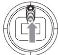
Elevator down

Left side view
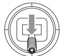
Elevator up
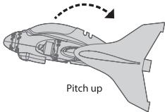
Left side view
9.0.2 Horizontal flight mode
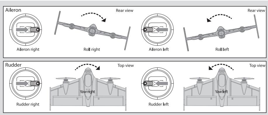
10.0 Flight Mode Description
Vertical flight mode:
In this mode, two propellers rotate to generate lift, make it fly vertically and move, hover or take off and land according to the player's control instruction, and even switch to this mode with a key in case of emergency Save the machine, to avoid unnecessary losses.

Horizontal self-stable flight mode: In this mode, the aircraft responds to pitch, ailerons and heading in the same way as a typical aircraft and constantly corrects itself, even if it is obstructed by an obstacle, simply removing it and continuing its flight back to normal. This mode, the pitch, aileron and heading are limited, this setting makes the control more intelligent, easier and more relaxed, so it is suitable for beginner player manipulation exercises.
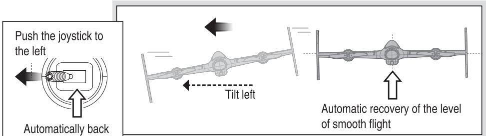
10.0 Flight Mode Description
Horizontal Manual Flight Mode: In this mode, the model has been completely transformed into a flexible, autonomous flying wing. No angle or self-balancing. In addition, because you have two front-end brushless motor thrust, then you have a strong power and speed, and it uses a differential control, so even you can use the different thrust of the motor for yaw control, Complete the wild rotation and rolling action. A substantial, long lift or aileron allows you to experience the most intense on-site experience while maneuvering, as well as performing a series of aerobatics.

11.0 Flight environment
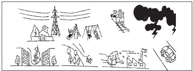
Do not use this product under the following conditions to avoid accidental injury or damage to the aircraft.
1) High-voltage line lots, parks, railway lots, highway lots
2) Thunderstorm, windy weather, rain and snow weather
natural_image
Illustration of a traffic accident scene with buildings, smoke, and a train (no text or symbols)
End the flight
Fly through


t
[Non-Text]
[Non-Text]
[Non-Text]
[Non-Text]
[Non-Text]
[Non-Text]
[Non-Text]
[Non-Text]
[Non-Text]
[Non-Text]
[Non-Text]
[Non-Text]
[Non-Text]
[Non-Text]
[Non-Text]
[Non-Text]
[Non-Text]
[Non-Text]
[Non-Text]
[Non-Text]
[Non-Text]
[Non-Text]
[Non-Text]
[Non-Text]
[Non-Text]


① Turn the flight mode to vertical flight mode and slowly land
② First turn off the aircraft power, then turn off the remote control power.
③ Remove the aircraft battery from the aircraft.


12.0 Troubleshooting
12.0.1 The no responding solution for Remote control and aircraft:
1) Make sure the code is OK!
2) If the battery is low or not.
12.1 FPV Troubleshooting
12.1.1 Goggles received poor quality image signal or wireless transmission distance close:
1) Is there any interference with radio transmitting equipment of the same frequency in the vicinity? The FPV system should choose other frequencies to avoid the interference frequency or to avoid using in the same place.
2) Whether the goggles antenna is installed.
3) Whether there are obstacles such as mountain, house and tree between the goggles and the aircraft. Please use the FPV system in the open space.
13.0 FLYSKY Receiver (1)
- Hold down the receiver BIND button then set up power, the indicator light flashing.
- Turn on the remote control and start up BIND button, the receiver indicator light will flash slowly.
- Turn off the remote control power then restart, the receiver indicator becomes long bright, the code is completed.
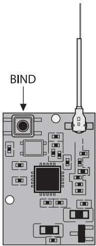
(Pic a)
13.1 FRSKY Receiver (2)
1. X9D remote control code method:
- Remote control select D8 mode
- Press and hold the receiver BIND button and set up power on the receiver, and the LED keep on long time.
- Select the remote control BIND button and start up, then LED light go off means the receiver over the frequency match.
- To exit the remote control checking mode, the receiver release BIND button, disconnect the receiver and then re-power to use at once.
2. DJT, DFT tuner method:
- First press and hold the tuner button and turn on the power of the remote control, then the tuner enters the tuner mode.
- Press and hold the BIND button on the receiver, then set up power for the receiver and make the frequency match. After the completion of the frequency the receiver LED will go off.
- Re-start the remote control, release the receiver BIND button and re-power to use at once.
3. XJT tuner method:
- XJT tuner dip switch to select D8 mode
- First press and hold the tuner button and turn on the power of the remote control, then the tuner enters the tuner mode.
- Press and hold the BIND button on the receiver, then set up power for the receiver and make the frequency match. After the completion of the frequency the receiver LED will go off.
- Re-start the remote control, release the receiver BIND button and re-power to use at once.

natural_image
Pure electrical circuit lines without any symbols
(Pic b)
14.0 Parts List
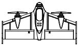 Aircraft x1 Aircraft x1 | 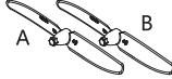 Propeller Ax2Propeller Bx2 Propeller Ax2Propeller Bx2 | 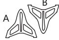 Vertical tail Ax1Vertical tail Bx1 Vertical tail Ax1Vertical tail Bx1 |  Velcro x1 Velcro x1 |
 Decorative stickers x1 Decorative stickers x1 | 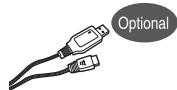 USB charging cable x1 USB charging cable x1 | 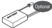 Aircraft battery x1 Aircraft battery x1 |  Manual x1 Manual x1 |
 FPV System Components x1 FPV System Components x1 | 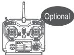 Remote control x1 Remote control x1 | 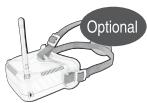 VR Goggles x1 VR Goggles x1 | |