
2100L - Récepteur audio MARANTZ - Notice d'utilisation et mode d'emploi gratuit
Retrouvez gratuitement la notice de l'appareil 2100L MARANTZ au format PDF.

| Type d'appareil | Radio AM/FM stéréophonique |
| Bandes de fréquences | AM et FM |
| Stéréophonie | Oui |
| Type de syntoniseur | Analogique |
| Alimentation | Secteur |
| Affichage | Non précisé |
| Contrôle de tonalité | Non précisé |
| Sortie audio | Stéréo |
| Dimensions | Non précisé |
| Poids | Non précisé |
| Fonctions supplémentaires | Non précisé |
| Type d'antenne | Non précisé |
| Compatibilité | Non précisé |
| Fabrication | Non précisé |
| Utilisation | Écoute radio AM/FM en stéréo |
FOIRE AUX QUESTIONS - 2100L MARANTZ
Questions des utilisateurs sur 2100L MARANTZ
0 question sur cet appareil. Repondez a celles que vous connaissez ou posez la votre.
Poser une nouvelle question sur cet appareil
Téléchargez la notice de votre Récepteur audio au format PDF gratuitement ! Retrouvez votre notice 2100L - MARANTZ et reprennez votre appareil électronique en main. Sur cette page sont publiés tous les documents nécessaires à l'utilisation de votre appareil 2100L de la marque MARANTZ.
MODE D'EMPLOI 2100L MARANTZ
SERVICE
MANUAL
text_image
marantz model 2100 Am/Fm Stereophonic TunerTABLE OF CONTENTS
Section Title Page
-
P.W. BOARDS 1
-
TEST EQUIPMENT REQUIRED FOR SERVICING 2
-
AM ALIGNMENT PROCEDURES 2
3.1 AM IF Alignment 2
3.2 AM Frequency Range and Tracking Alignment 2
- FM ALIGNMENT PROCEDURES 2
4.1 FM Frequency Range and Tracking Alignment 2
4.2 Stereo Separation Alignment 3
4.3 Muting Threshold Adjustment 3
4.4 FM Output Level Adjustment 3
-
VOLTAGE CONVERSION FOR EUROPEAN MODEL 3
-
DIAGRAMS 5
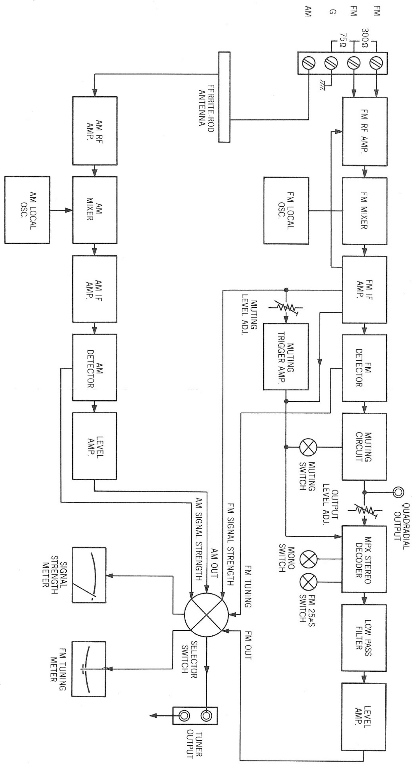
6.1 Block Diagram 5
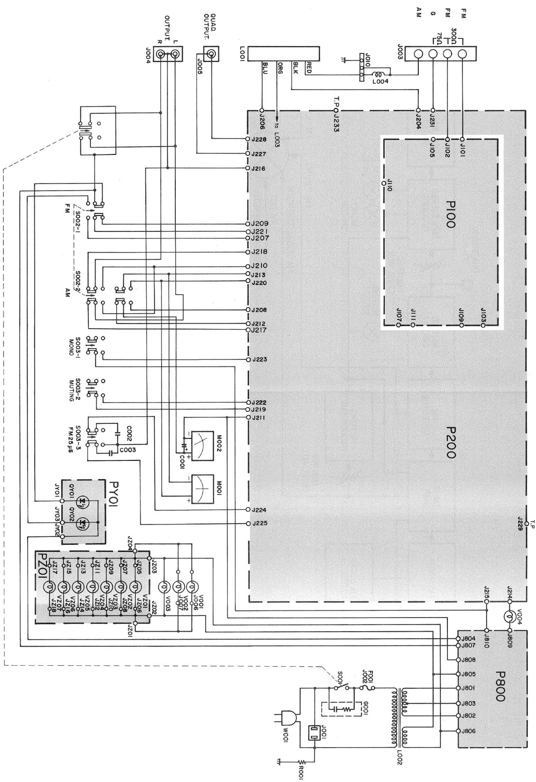
6.2 Connection Diagram - U.S.A. & Canada 7
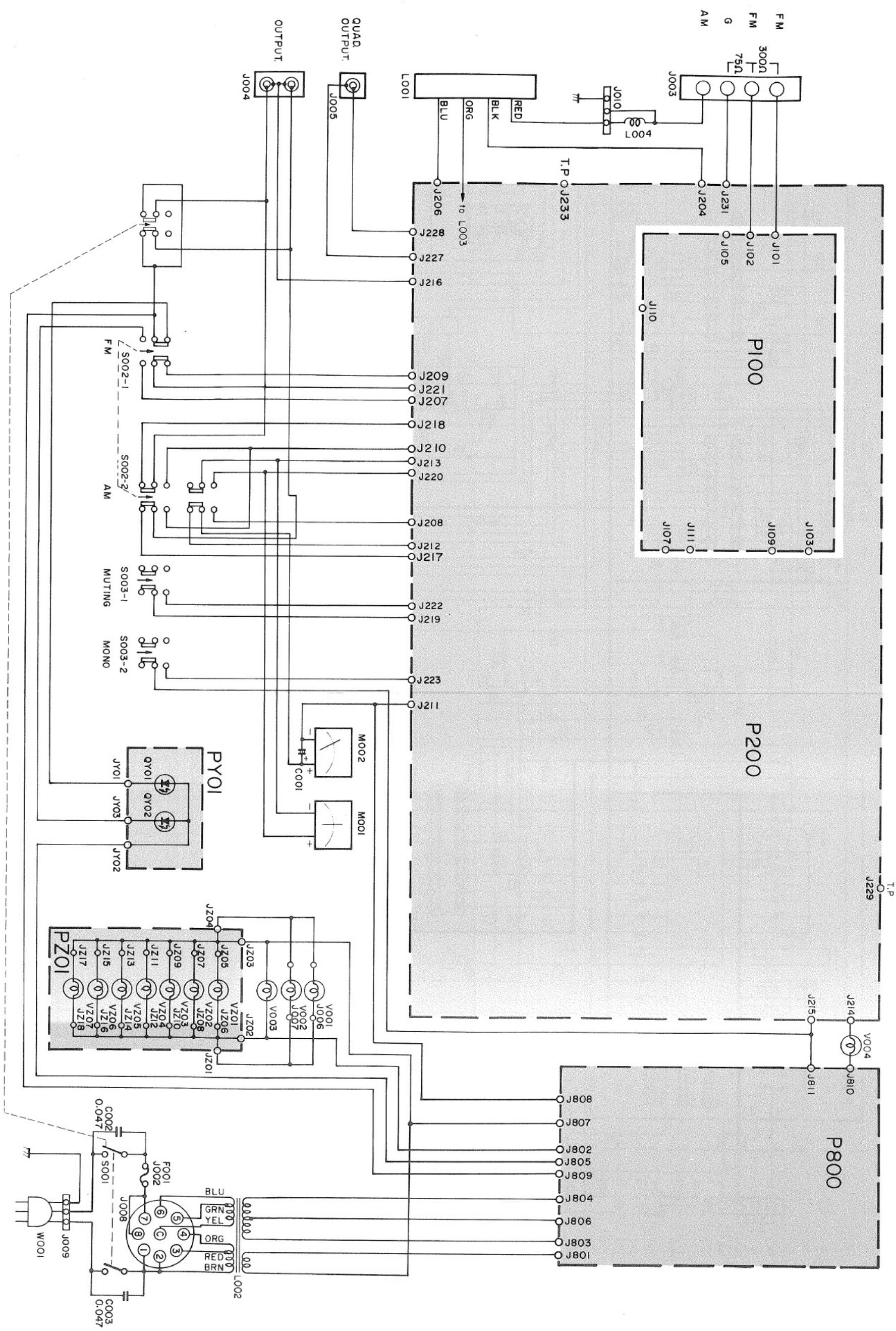
6.3 Connection Diagram - Europe 9
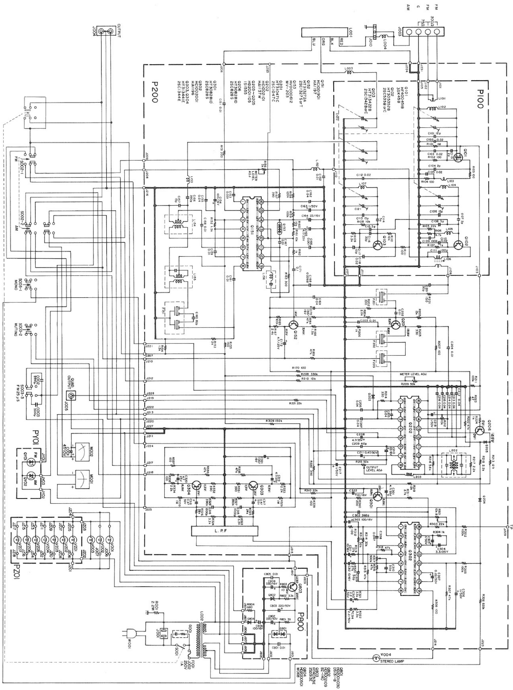
6.4 Schematic Diagram - U.S.A. & Canada 11
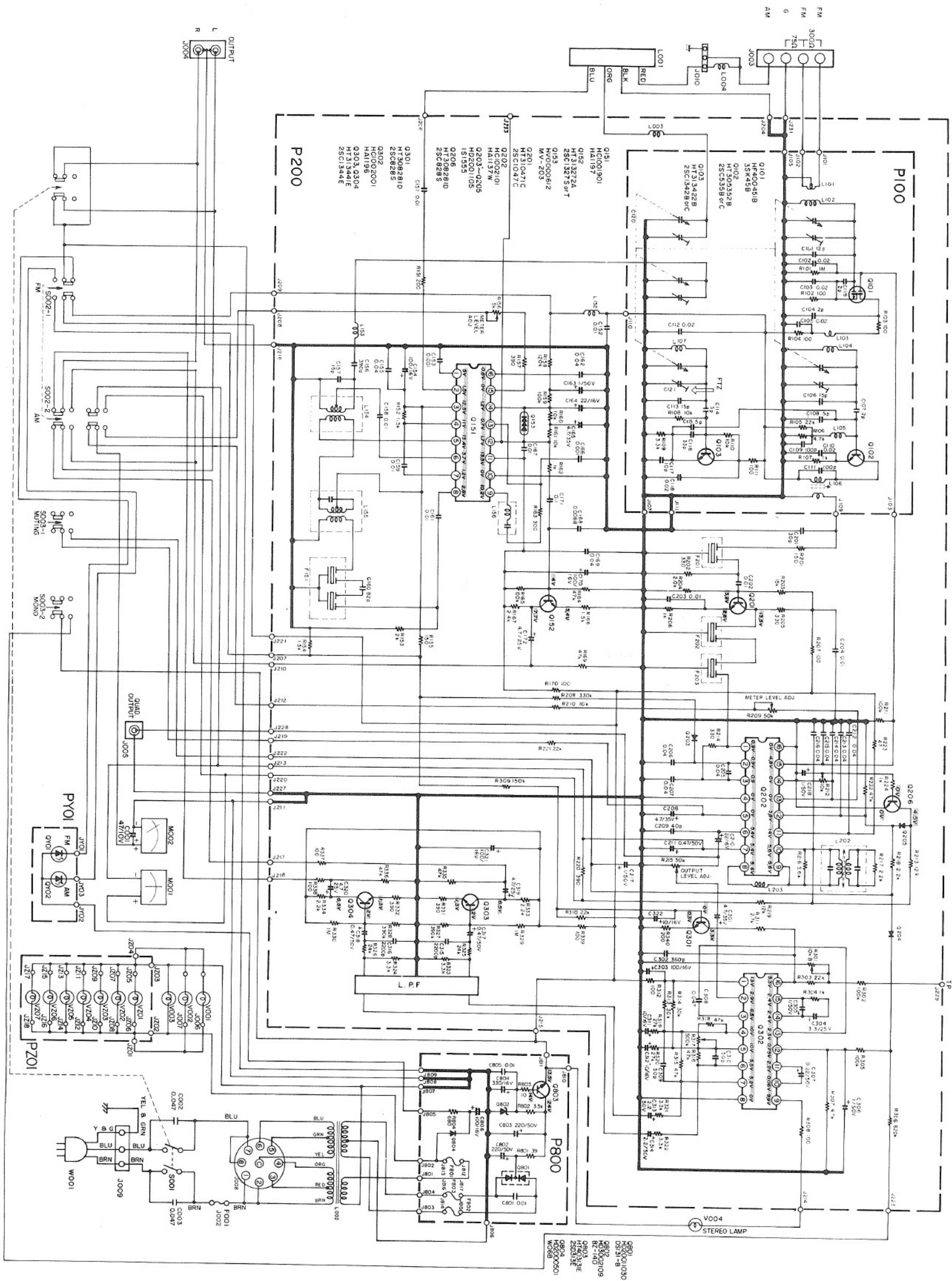
6.5 Schematic Diagram - Europe 13
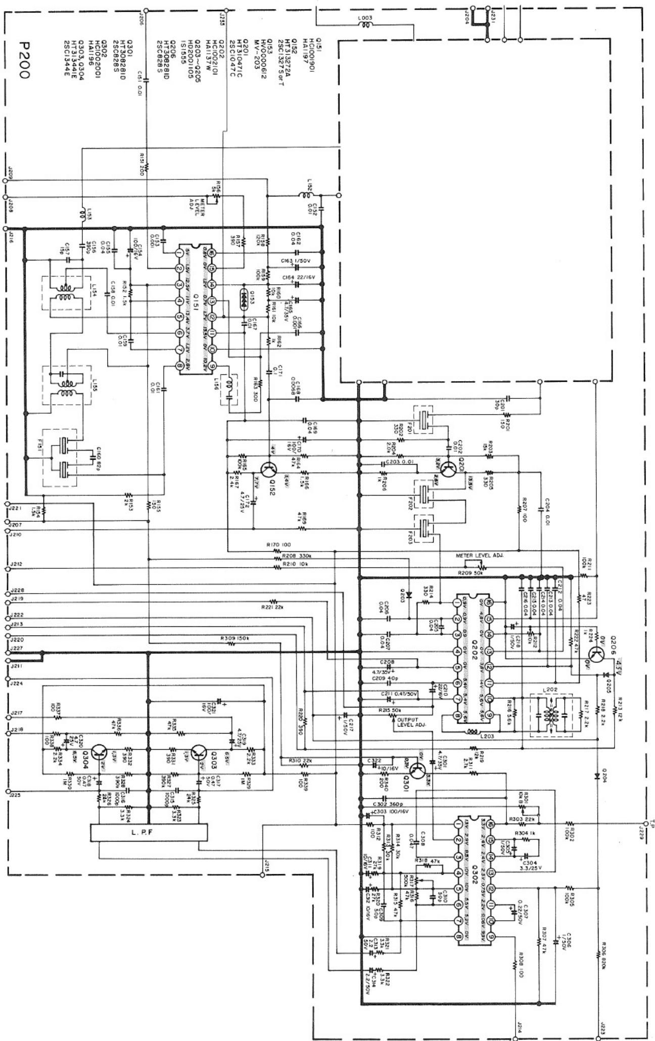
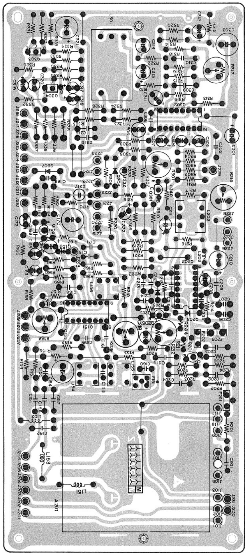
6.6 Tuner Board Schematic Diagram and Component Locations - P200 15
6.7 Front End Board Schematic Diagram and Component Locations - P100 19
6.8 Power Supply Board Schematic Diagram and Component Locations - P800 - U.S.A. & Canada 20
6.9 Power Supply Board Schematic Diagram and Component Locations - P800 - Europe 20
6.10 Function Indicator Board Schematic Diagram and Component Locations - PY01 21
6.11 Dial Lamp Board Schematic Diagram and Component Locations - PZ01 21
- MAJOR COMPONENT LOCATIONS 22
7.1 Cabinet - Front View - U.S.A. & Canada 22
7.2 Chassis - Top View - U.S.A. & Canada 22
7.3 Cabinet - Rear View - U.S.A. & Canada 23
7.4 Chassis - Bottom View - U.S.A. & Canada 23
7.5 Cabinet - Front View - Europe 24
7.6 Chassis - Top View - Europe 24
7.7 Cabinet - Rear View - Europe 25
7.8 Chassis - Bottom View - Europe 25
- EXPLODED VIEWS 26
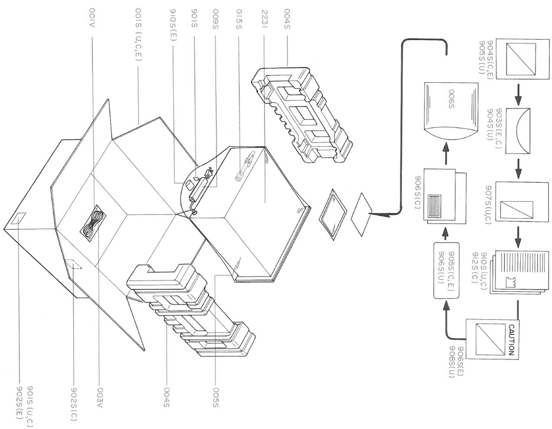
8.1 Packing Material Exploded View 26
8.2 Mechanical Exploded View 27
-
PARTS LIST 29
-
TECHNICAL SPECIFICATIONS 34
INTRODUCTION
This service manual was prepared for use by Authorized Warranty Stations and contains service information for Marantz Model 2100 AM/FM Stereophonic Tuner.
Servicing information and voltage data included in this manual are intended for use by the knowledgeable and experienced technician only. All instructions should be read carefully. No attempt should be made to proceed without a good understanding of the operations in the receiver.
The parts list furnishes information by which replacement parts may be ordered from the Marantz Company. A simple description is included for parts which can usually be obtained through local suppliers.
1. P.W. BOARDS
As can be seen from the circuit diagram, the chassis of Model 2100 consists of the following units. Each unit mounted on a printed circuit board is described within the square enclosed by a bold dotted line on the circuit diagram.
- Front End .... mounted on P.W. Board P100
- Tuner ..... mounted on P.W. Board P200
- Power Supply ..... mounted on P.W. Board P800
- Dial Lamp ..... mounted on P.W. Board PZ01
- Function Indicator .... mounted on P.W. Board PY01
text_image
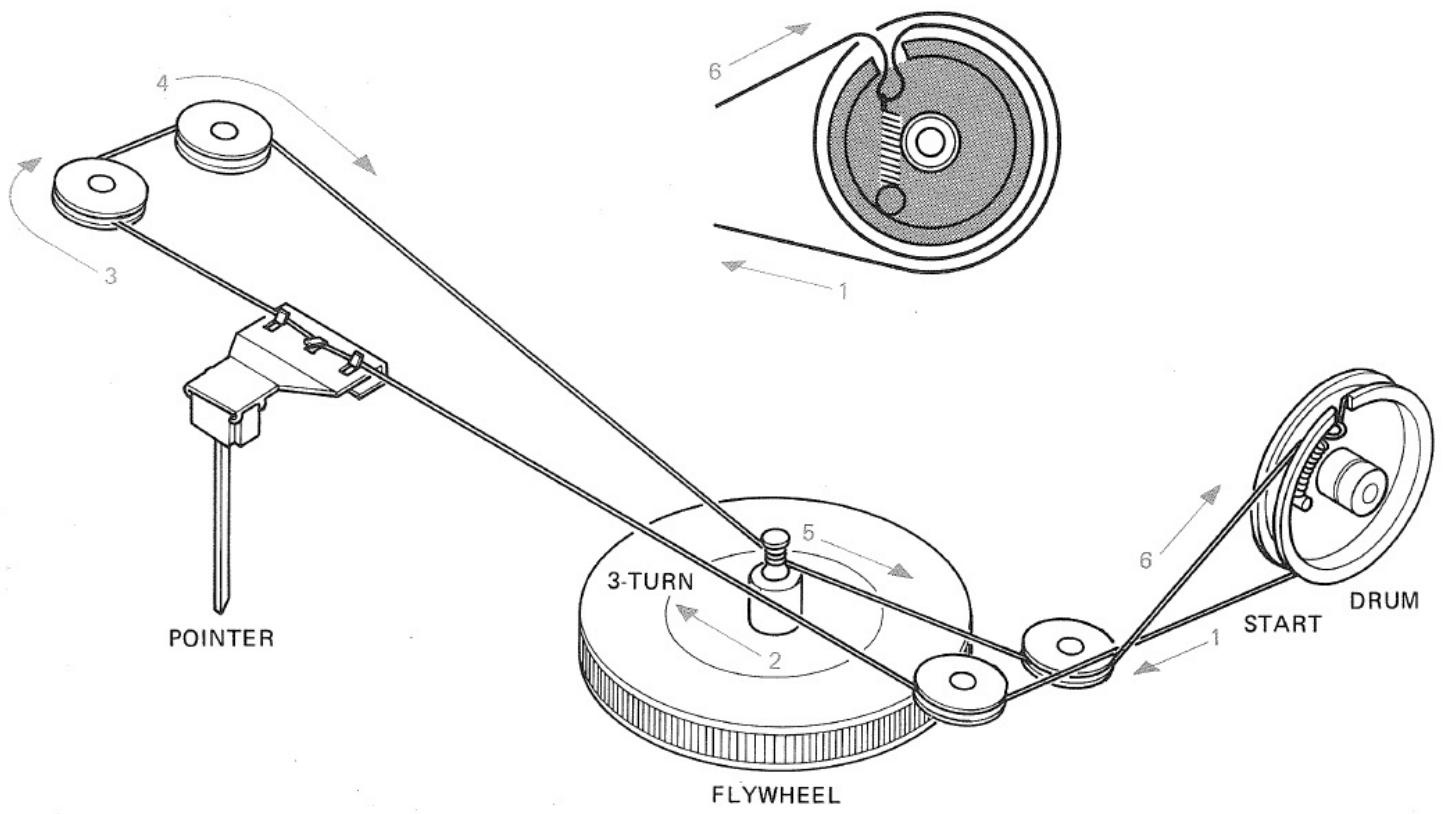
4 3 6 1 3-TURN 5 2 6 1 START DRUM POINTER FLYWHEELFigure 1. Dial Stringing
2. TEST EQUIPMENT REQUIRED FOR SERVICING
This table lists the test equipment required for servicing the Model 2100 Tuner.
| Item | Manufacturer and Model No. | Use |
| AM Signal Generator | Signal source for AM alignment | |
| Test Loop | Use with AM Signal Generator | |
| FM Signal GeneratorMPX Signal Generator | Sound TechnologyModel 1000A | Signal source for FM alignmentStereo separation alignment and trouble shooting |
| Distortion AnalyzerAudio OscillatorAC VTVM | Sound TechnologyModel 1700A | Distortion measurementsSinewave and squarewave signal sourceVoltage measurements (AC) |
| Oscilloscope | Tektronix Model T932Philips Model 3232 | Waveform analysis and trouble shooting |
| Frequency Counter | Fluke Model 1900A | MPX Oscillator adjustment (VCO) |
| Circuit Tester | Trouble shooting | |
| DC VTVM | Fluke Model 8000 “Digital” Simpson Model 313, Triplet Model 801 | Voltage measurements (DC) |
| AC Wattmeter | Simpson Model 1379 | Monitors primary power to tuner |
| Line Voltmeter | Simpson Model 1359 | Monitors potential of primary power to tuner |
| Variable Autotransformer | Superior Electronic Co.,Powerstat Model 116B-10A | Adjusts level of primary power to tuner |
3. AM ALIGNMENT PROCEDURES
3.1 AM IF ALIGNMENT
- Connect a sweep generator to the L153 and an alignment scope to the J233 (T.P.).
- Rotate each core of IF transformers L155 and L156 for the maximum height and flat top symmetrical response.
3.2 AM FREQUENCY RANGE AND TRACKING ALIGNMENT
- Set AM signal generator to 515 kHz. Turn the tuning capacitor fully closed (place the tuning pointer at the low end) and adjust the oscillator coil L154 for maximum audio output.
- Set the signal generator to 1650kHz . Place the tuning pointer in the high frequency end and adjust the oscillator trimmer on the oscillator tuning capacitor for maximum audio output.
- Repeat steps 1 and 2 until no further adjustment is necessary.
- Set the generator to 600kHz , tune the tuner to the same frequency and adjust a slug core of AM ferrite-rod antenna L001 for maximum output.
- Set the generator to 1400kHz and tune the tuner to the same frequency and adjust the trimming capacitor on the antenna tuning capacitor for maximum output.
- Repeat procedures 4 and 5 until no further adjustment is necessary.
NOTE: During tracking alignment reduce the signal generator output as necessary to avoid AGC action.
4. FM ALIGNMENT PROCEDURES
4.1 FM FREQUENCY RANGE AND TRACKING ALIGNMENT
- Connect an FM signal generator to the FM antenna terminals and an oscilloscope and an audio distortion analyzer to the OUTPUT jacks on the rear panel.
- Set the generator to 87.4MHz and provide about 3 to 5 V . Place the tuning pointer at the low frequency end by rotating the tuning knob and adjust the pitch of oscillator coil L107 to obtain maximum audio output.
- Set the generator to 109 MHz and provide about 3 to 5 V. Rotate the tuning knob and place the tuning pointer at the high frequency end and adjust the trimming capacitor C121 for maximum output.
- Repeat steps 2 and 3 until no further adjustment is necessary.
- Set the generator to 90MHz and tune the tuner to the same frequency. Decrease signal generator output until the audio output level decreases with the decreasing generator output. Adjust the pitch of antenna coil L102 and RF coil L104 for maximum output.
- Set the generator to 106 MHz and tune the tuner to the same frequency. Decrease the signal generator output until the audio output level decreases with the decreasing generator output. Adjust the trimming capacitors of antenna and RF tuning circuits for maximum output.
- Repeat steps 5 and 6 until no further adjustment is necessary.
- Adjust the primary core (lower core) of discriminator transformer L202 so that the center tuning meter point-
er indicates its center at no signal applied. Set the FM signal generator to 98 MHz and increase its output level 1 k V and tune the tuner to the same frequency so that the center tuning meter pointer indicates its center. Adjust the secondary core (upper core) of L202 for minimum distortion.
4.2 STEREO SEPARATION ALIGNMENT
- Set the FM signal generator to provide 1 k V at 98 MHz. Tune the tuner to the same frequency so that the center tuning meter pointer indicates its center. Then turn off the modulation of the generator, connect a frequency counter to test point J229 and adjust R301 so that the frequency counter may precisely read 76 kHz.
- Modulate the generator with stereo composite signal consisting of only L or R channel (of course a pilot signal must be included).
- Adjust the trimming resistor R317 for maximum and same separation in both channels.
4.3 MUTING THRESHOLD ADJUSTMENT
- Set the FM signal generator output to provide 12.5 V (IHF) at 98 MHz and tune tuner to the same frequency.
Adjust the trimming resistor R212 for the threshold level of 12.5 V . (During this adjustment turn the FM MUTING pushswitch “on”).
4.4 FM 25 μS OUTPUT LEVEL ADJUSTMENT
- Set the FM signal generator to provide a 400 Hz, 50% modulated 98 MHz mono signal, at 1 k V output. Precisely tune the tuner to 98 MHz.
- Depress the FM 25 S pushswitch, and adjust R215 until the outputs of both channels are 580 mV.
5. VOLTAGE CONVERSION FOR EUROPEAN MODEL
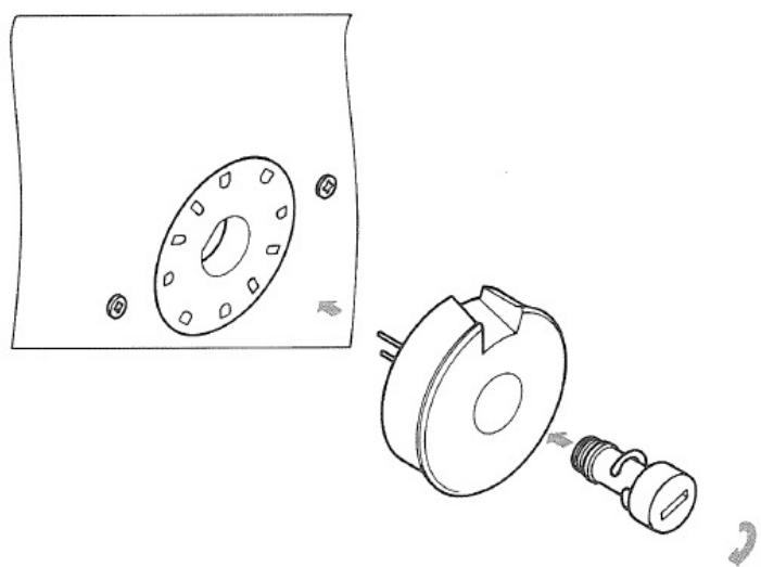
The European version of the Model 2100 is equipped with a universal power transformer that may be adjusted to operate at 110 V, 120 V, 220 V, or 240 V AC at 50 to 60 Hz. To convert the unit to a different power source voltage, reposition conversion plug as shown in Figure 2.
CAUTION: DISCONNECT POWER SUPPLY CORD FROM AC OUTLET BEFORE CONVERTING VOLTAGE.
natural_image
Technical line drawing of a mechanical assembly with flange, housing, and screw (no text or symbols)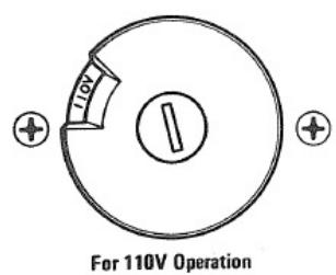
text_image
110V For 110V Operation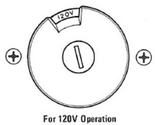
text_image
120V For 120V Operation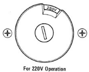
text_image
220V For 220V Operation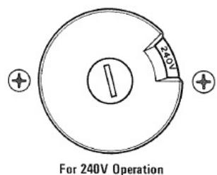
text_image
For 240V OperationFigure 2. Voltage Conversion Chart
FTZ REGULATION
Instruction for the use in the range other than specified in FTZ codes.
Achtung für die Leute, die in dem Gebiet wohnen, wo die FTZ-Bestimmungen vorherrschend sind.
Sollte des Gerät auch für Frequenzen auszerhalb des in den FTZ-Bestimmungen angegebenen Bereiches empfangebereit sein, bitten wir, den Bereich durch Nachstellen des Kernes in der Oszillatorspule (in der Abbildung mit "FTZ" gekennzeichnet) so zu korrigieren, dass er den Bestimmungen entspricht.
flowchart
graph TD
    A["FM 300Ω"] --> B["FM RF AMP."]
    C["FM 75Ω"] --> D["FM MIXER"]
    E["G"] --> F["FM IF AMP."]
    G["AM"] --> H["FERRITE-ROD ANTENNA"]
    H --> I["AM RF AMP."]
    I --> J["AM MIXER"]
    J --> K["AM IF AMP."]
    L["FM LOCAL OSC."] --> M["MUTING TRIGGER AMP."]
    N["FM DETECTOR"] --> O["MUTING CIRCUIT"]
    P["MUTING SWITCH"] --> Q["MPX STEREO DECODER"]
    R["OUTPUT LEVEL ADJ."] --> S["MPX STEREO DECODER"]
    T["MONO SWITCH"] --> U["MPX STEREO DECODER"]
    V["FM 25μS SWITCH"] --> W["MPX STEREO DECODER"]
    X["TUNER OUTPUT"] --> Y["Selector SWITCH"]
    Z["AM OUT"] --> AA["AM SIGNAL STRENGTH"]
    AB["SIGNAL STRENGTH METER"] --> AC["AM SIGNAL STRENGTH"]
    AD["FM TUNING METER"] --> AE["AM SIGNAL STRENGTH"]
    AF["TUNER OUTPUT"] --> AG["AM SIGNAL STRENGTH"]
    AH["QUADRADIAL OUTPUT"] --> AI["MPX STEREO DECODER"]
    AJ["LOW PASS FILTER"] --> AK["MPX STEREO DECODER"]
    AL["LEVEL AMP."] --> AM["MPX STEREO DECODER"]
text_image
PZ01 2JZ17 2JZ16 2JZ15 2JZ14 2JZ13 2JZ12 2JZ11 2JZ10 2JZ09 2JZ08 2JZ07 2JZ06 2JZ05 2JZ04 2JZ03 2JZ02 2JZ01 V003 V002 V001 V000 PY01 QV01 QV02 S003-3 FM25 fis COO3 COO2 SOO3-2 MOINO SOO3-MONO SOO3-MONO AM COO1 COO2 M001 M002 U255 U244 U239 U236 U233 U231 U229 U227 U225 U223 U221 U219 U217 U216 U215 U214 U213 U212 U211 U210 U209 U208 U207 U206 U205 U204 U203 U202 U201 U200 PPO0 P800 1.7" V004 1.5" V809 1.810 1.915 PPO0 P800 FMA 75N AM 6 75N AM FM 300N AM FL 10 LO03 BLu 16 17 18 19 20 21 22 23 24 25 26 27 28 29 30 31 32 33 34 35 36 37 38 39 40 41 42 43 44 45 46 47 48 49 50 51 52 53 54 55 56 57 58 59 60 61 62 63 64 65 66 67 68 69 70 71 72 73 74 75 76 AM6.2 CONNECTION DIAGRAM - U.S.A. & CANADA
text_image
P800 1.5 2.14 2.15 2.16 2.17 2.18 2.19 2.20 2.21 2.22 2.23 J107 J108 J109 J110 J111 J103 J104 J105 J106 J107 J108 J109 J110 J111 J103 J104 J105 J106 J107 J108 J109 J110 J111 J103 J104 J105 J106 J107 J109 J110 J111 J103 J104 J105 J106 J107 J109 J110 J111 J103 J104 J105 J106 J107 J109 J110 J111 J102 J103 J104 J105 J106 J107 J109 J110 J111 J103 J104 J105 J106 J107 J109 J110 J111 J103 J104 J105 J107 J109 J110 J111 J103 J104 J105 J106 J107 J109 J110 J111 J103 J104 J105 J106 J107 J109 J110 J11I J229 P80Zd P8ZbZbZbZbZbZbZbZbZbZbZbZbZbZbZbZbZbZbZbZbZbZbZbZbZbZbZbZbZbZbZbZbZbZbZbZbZbZbZbZbZbZbZbZbZbZbZbZbZbZbZaMAMMUMINGSMMOLOMOOIOOMOIOOMOIOOMOIOOMOIOOMOIOOMOIOOMOIOOMOIOOMOIOOMOIOOMOIOOMOIOOMOIOOMOIOOMOIOOMOIOOMOIOOMOIOOMOIOOMOIOOMOIOOMOIOOMOIOOMOIOOMOIOOMOIOOMOIOOMOIOOMOIOOMOIOOMOIOOMOIOOMOIOOMoIOOMoIOOMoIOOMoIOOMoIOOMoIOOMoIOOMoIOOMoIOOMoIOOMoIOOMoIOOMoIOOMoIOOMoIOOMoIOOMoIOOMoIOOMoIOOMoIOOMoIOOMoIOOMoIOOMoIOOMoIOOMoIOOMoIOOMoIOOMoIOOMoIOOMoIOOMoIOOMoIOOMoioomomomomomomomomomomomomomomomomomomomomomomomomomomomomomomomomomomomomomomomomomomomomomomomomomomomomomomomomomomomomomomomomomomomomomomomomomomomomomomomomomomomomomomomomomomomomomomomomomomomomohmamamamamamamamamamamamamamamamamamamamamamamamamamamamamamamamamamamamamamamamamamamamamamamamamamamamamamamamamamamamamamamamamamamamamamamamamamamamamamamamamamamamamamamamamamumonononononononononononononononononononononononononononononononononononononononononononononononononononononononononononononononononononononononononononononononononononononononononononononononononononononeououououououououououououououououououououououououououououououououououououououououououououououououououououououououououououououououououououououououououououououououououououououououououououououououououououauuoooooooooooooooooooooooooooooooooooooooooooooooooooooooooooooooooooooooooooooooooooooooooooooooooooooooooooooooooooooooooooooooooooooooooooooooooooooooooooooooooooooooooooooooooooooooooooooooooaaacaaacaaacaaacaaacaaacaaacaaacaaacaaacaaacaaacaaacaaacaaacaaacaaacaaacaaacaaacaaacaaacaaacaaacaaacaaacaaacaaacaaacaaacaaacaaacaaacaaacaaacaaacaaacaaacaaacaaacaaacaaacaaacaaacaaacaaacaaacaaacaaacaaacaaocuaoutopoutpoutpoutpoutpoutpoutpoutpoutpoutpoutpoutpoutpoutpoutpoutpoutpoutpoutpoutpoutpoutpoutpoutpoutpoutpoutpoutpoutpoutpoutpoutpoutpoutpoutpoutpoutpoutpoutpoutpoutpoutpoutpoutpoutpoutpoutpoutpoutpoutpoutpoutpputpputpputpputpputpputpputpputpputpputpputpputpputpputpputpputpputpputpputpputpputpputpputpputpputpputpputpputpputpputpputpputpputpputpputpputpputpputpputpputpputpputpputpputpputpputpputpputpputpputppurpputpputpputpputpputpputpputpputpputpputpputpputpputpputpputpputpputpputpputpputpputpputpputpputpputpputpputpputpputpputpputpputpputpputpputpputpputpputpputpputpputpputpputpputpputPPUTPPUTPPUTPPUTPPUTPPUTPPUTPPUTPPUTPPUTPPUTPPUTPPUTPPUTPPUTPPUTPPUTPPUTPPUTPPUTPPUTPPUTPPUTPPUTPPUTPPUTPPUTPPUTPPUTPPUTPPUTPPUTPPUTPPUTPPUTPPUTPPUTPPUTPPUTPPUTPPUTPPUTPPUTPPUTPPUTPPUTPPUTPPUTPPUTPPUTPPATUOPUOPUOPUOPUOPUOPUOPUOPUOPUOPUOPUOPUOPUOPUOPUOPUOPUOPUOPUOPUOPUOPUOPUOPUOPUOPUOPUOPUOPUOPUOPUOPUOPUOPUOPUOPUOPUOPUOPUOPUOPUOPUOPUOPUOPUOPUOPUOPUOPUOPUUP UO O O O O O O O O O O O O O O O O O O O O O O O O O O O O O O O O O O O O O O O O O O O O O O O O O O O O O O O O O O O O O O O O O O O O O O O O O O O O O O O O O O O O O O O O O O O O O O O O O O O O I U 2233 2233 2233 2233 2233 2233 2233 2233 2233 2233 2233 2233 2233 2233 2233 2233 2233 2233 2233 2233 223C 223C 223C 223C 223C 223C 223C 223C 223C 223C 223C 223C 223C 223C 223C 223C 223C 223C 223C 223C 223 C 223 C 223 C 223 C 223 C 223 C 223 C 223 C 223 C 223 C 223 C 223 C 223 C 223 C 223 C 223 C 223 C 223 C 223 C 223 C 223C 875N 75N FMFMFMFMFMFMFMFMFMFMFMFMFMFMFMFMFMFMFMFMFMFMFMFMFMFMFMFMFMFMFMFMFMFMFMFMFMFMFMFMFMFMFMFMFMFMFMFMFMFMFMFMFMFMFMFMFMFMFMFMFMFMFMFMFMFMFMFMFMFMFMFMFMFMFMFMFMFMFMFMFMFMFMFMFMFMFMFMFMFMFMFMFMFMFMFMFMFMFMFMFMF M FM FM FM FM FM FM FM FM FM FM FM FM FM FM FM FM FM FM FM FM FM FM FM FM FM FM FM FM FM FM FM FM FM FM FM FM FM FM FM FM FM FM FM FM FM FM FM FM FM FM FM FM FM FM FM FM FM FM FM FM FM FM FM FM FM FM FM FM FM FM FM FM FM FM FM FM FM FM FM FM FM FM FM FM FM FM FM FM FM FM FM FM FM FM FM FM FM FM FM FM F M F M F M F M F M F M F M F M F M F M F M F M F M F M F M F M F M F M F M F M F M F M F M F M F M F M F M F M F M F M F M F M F M F M F M F M F M F M F M F M F M F M F M F M F M F M F M F M F M F M F F M F M F M F M F M F M F M F M F M F M F M F M F M F M F M F M F M F M F M F M F M F M F M F M F M F M F M F M F M F M F M F M F M F M F M F M F M F M F M F M F M F M F M F M F M F M F M F M F M F MFMFMFMMFMMFMMFMMFMMFMMFMMFMMFMMFMMFMMFMMFMMFMMFMMFMMFMMFMMFMMFMMFMMFMMFMMFMMFMMFMMFMMFMMFMMFMMFMMFMMFMMFMMFMMFMMFMMFMMFMMFMMFMMFMMFMMFMMFMMFMMFMMFMMFMMFMMF MM GMMGMGMGMGMGMGMGMGMGMGMGMGMGMGMGMGMGMGMGMGMGMGMGMGMGMGMGMGMGMGMGMGMGMGMGMGMGMGMGMGMGMGMGMGMGMGMGMGMGMGMGMGMGMGMGMGMGMGMGMGMGMGMGMGMGMGMGMGMGMGMGMGMGMGMGMGMGMGMGMGMGMGMGMGMGMGMGMGMGMGMGMGMGMGMGMGMGMGMGMGMGAMMAMMAMMAMMAMMAMMAMMAMMAMMAMMAMMAMMAMMAMMAMMAMMAMMAMMAMMAMMAMMAMMAMMAMMAMMAMMAMMAMMAMMAMMAMMAMMAMMAMMAMMAMMAMMAMMAMMAMMAMMAMMAMMAMMAMMAMMAMMAMMAMMAMMAMmAaAaAaAaAaAaAaAaAaAaAaAaAaAaAaAaAaAaAaAaAaAaAaAaAaAaAaAaAaAaAaAaAaAaAaAaAaAaAaAaAaAaAaAaAaAaAaAaAaAaA a A a A a a a a a a a a a a a a a a a a a a a a a a a a a a a a a a a a a a a a a a a a a a a a a a a a a a a a a a a a a a a a a a a a a a a a a a a a a a a a a a a a a a a a a a a a a a a a a a a a a a a a c m f m f m f m f m f m f m f m f m f m f m f m f m f m f m f m f m f m f m f m f m f m f m f m f m f m f m f m f m f m f m f m f m f m f m f m f m f m f m f m f m f m f m f m f m f m f m f m f m f m f m e o u o o o o o o o o o o o o o o o o o o o o o o o o o o o o o o o o o o o o o o o o o o o o o o o o o o o o o o o o o o o o o o o o o o o o o o o o o o o o o o o o o o o o o o o o o o o o o o o o o o o o n e u p u t p u t p u t p u t p u t p u t p u t p u t p u t p u t p u t p u t p u t p u t p u t p u t p u t p u t p u t p u t p u t p u t p u t p u t p u t p u t p u t p u t p u t p u t p u t p u t p u t p u t P U T U T U T U T U T U T U T U T U T U T U T U T U T U T U T U T U T U T U T U T U T U T U T U T U T U T U T U T U T U T U T U T U T U T U T U T U T U T U T U T U T U T U T U T U T U T U T U T U T U T U6.3 CONNECTION DIAGRAM·EUROPE
text_image
P200 P100 P800 OUTRUT 1000 1000 1000 1000 1000 1000 1000 1000 1000 1000 1000 1000 1000 1000 1000 1000 1000 1000 1000 1000 100 P201 P201 P201 P201 P201 P201 P201 P201 P201 P201 P201 P201 P201 P201 P201 P201 P201 P201 P201 P201 P202 P202 P202 P202 P202 P202 P202 P202 P202 P202 P202 P202 P202 P202 P202 P203 P203 P203 P203 P203 P203 P203 P203 P203 P203 P203 P203 P203 P203 P203 P203 P203 P203 P203 P203 P204 P204 P204 P204 P204 P204 P204 P204 P204 P204 P204 P204 P204 P204 P204 P204 P204 P205 P205 P205 P205 P205 P205 P205 P205 P205 P205 P205 P205 P205 P205 P205 P206 P206 P206 P206 P206 P206 P206 P206 P206 P206 P206 P206 P206 P206 P206 P206 P206 P206 P207 P207 P207 P207 P207 P207 P207 P207 P207 P207 P207 P207 P207 P207 P207 P207 P219 1999 1999 1999 1999 1999 1999 1999 1999 1999 1999 1999 1999 1999 1999 1999 1999 1999 1999 1999 1999 1988 1988 1988 1988 1988 1988 1988 1988 1988 1988 1988 1988 1988 1988 1988 1988 1988 1988 1988 1988 1987 1987 1987 1987 1987 1987 1987 1987 1987 1987 1987 1987 1987 1987 1987 1987 1987 1987 1987 1987 1986 1986 1986 1986 1986 1986 1986 1986 1986 1986 1986 1986 1986 1986 1986 1986 1986 1986 1986 1986 1985 1985 1985 1985 1985 1985 1985 1985 1985 1985 1985 1985 1985 1985 1985 1985 1985 1985 1985 1985 1984 1984 1984 1984 1984 1984 1984 1984 1984 1984 1984 1984 1984 1984 1984 1984 1984 1984 1984 19846.4 SCHEMATIC DIAGRAM·U.S.A. & CANADA
text_image
P100 FM 30Ω FM 75Ω G AM J003 LOO4 LED RED BLK DNG BLU Q101 HF400-45/B 5X45B Q102 HT305352B 2SC5358/FC Q103 HT313422B 2SC3428/FC Q104 Q105 Q106 Q107 Q108 Q109 Q110 Q111 Q112 Q113 Q114 Q115 Q116 Q117 Q118 Q119 Q120 Q121 Q122 Q123 Q124 Q125 Q126 Q127 Q128 Q129 Q130 Q131 Q132 Q133 Q134 Q135 Q136 Q137 Q138 Q139 Q140 Q141 Q142 Q143 Q144 Q145 Q146 Q147 Q148 Q149 Q150 Q151 Q152 Q153 Q154 Q155 Q156 Q157 Q158 Q159 Q160 Q161 Q162 Q163 Q164 Q165 Q166 Q167 Q168 Q169 Q170 Q171 Q172 Q173 Q174 Q175 Q176 Q177 Q178 Q179 Q180 Q181 Q182 Q183 Q184 Q185 Q186 Q187 Q188 Q189 Q190 Q191 Q192 Q193 Q194 Q195 Q196 Q197 Q198 Q199 Q200 P200 P800 P20I HDDOIO-030 05B3-IB QBDI HDDOIO-030 05B3-IB QBDI HDDOIO-030 05B3-IB QBDI HDDOIO-030 05B3-IB QBDI HDDOIO-030 05B3-IB QBDI HDDOIO-030 05B3-IB QBDI HDDOIO-030 QBDI HDDOIO-030 05B3-IB QBDI HDDOIO-030 05B3-IB QBDI HDDOIO-030 05B3-IB QBDI HDDOIO-030 05B3-IB QBDI HDDOIO-030 05B3-IB QBDI HDDOIO-040 QBDI HDDOIO-040 05B3-IB QBDI HDDOIO-040 05B3-IB QBDI HDDOIO-040 05B3-IB QBDI HDDOIO-040 05B3-IB QBDI HDDOIO-040 05B3-IB QBDI HDDOIO-040 05B3-IB QBDI HDDOIO-05B RBDI HDDOIO-05B RBDI HDDOIO-05B RBDI HDDOIO-05B RBDI HDDOIO-05B RBDI HDDOIO-05B RBDI HDDOIO-05B RBDI HDDOIO-05B RBDI HDDOIO-05B RBDI HDDOIO-05B RBCR GND C.267 2.6x V. T. T. T. T. T. T. T. T. T. T. T. T. T. T. T. T. T. T. T. T. T. T. T. T. T. T. T. T. T. T. T. T. T. T. T. T. T. T. T. T. T. T. T. T. T. T. T. T. T. T.6.5 SCHEMATIC DIAGRAM - EUROPE
text_image
P200 051 015 050 031 020 011 000 0000612 M-W-03 050131274 H11179 H11178 0232 R207 R207 R207 R207 R207 R207 R207 R207 R207 R207 R207 R207 R207 R207 R207 R207 R207 R207 R207 R207 R206 R206 R206 R206 R206 R206 R206 R206 R206 R206 R206 R206 R206 R206 R206 R206 R206 R206 R206 R206 R205 R205 R205 R205 R205 R205 R205 R205 R205 R205 R205 R205 R205 R205 R205 R205 R205 R205 R205 R205 R204 R204 R204 R204 R204 R204 R204 R204 R204 R204 R204 R204 R204 R204 R204 R204 R204 R204 R204 R204 R203 R203 R203 R203 R203 R203 R203 R203 R203 R203 R203 R203 R203 R203 R203 R203 R203 R203 R203 R203 R202 R202 R202 R202 R202 R202 R202 R202 R202 R202 R202 R202 R202 R201 R201 R201 R201 R201 R201 R201 R201 R201 R201 R201 R201 R201 R199 8.749 8.749 8.749 8.749 8.749 8.749 8.749 8.749 8.749 8.749 8.749 8.749 8.749 8.749 8.749 8.749 8.749 8. C191 8.749 8.749 8.749 8.749 8.749 8.749 8.749 8.749 8.749 8.749 8.749 8.749 8. C191 8.749 8.749 8.749 8,8,8,8,8,8,8,8,8,8,8,8,8,8,8,8,8,8,8,8,8,8,8,8,8,8,8,8,8,8,8,8,8,8,8,8,8,8,8,8,8,8,8,8,8,8,8,8,8,8,8, C191 8.749 8.749 8.749 8.749 8.749 8.749 8.749 8.749 8.749 8.749 8.749 8.749 8.749 8. C191 8.749 8.749 8,8,8,8,8,8,8,8,8,8,8,8,8,8,8,8,8,8,8,8,8,8,8,8,8,8,8,8,8,8,8,8,8,8,8,8,8,8, C191 8.749 8.749 8.749 6.366 6.366 6.366 6.366 6.366 6.366 6.366 6.366 6.366 6.366 6.366 6.366 6.366 6.366 6.366 6.366 6.366 6.555 6.555 6.555 6.555 6.555 6.555 6.555 6.555 6.555 6.555 6.555 6.555 6.555 6.555 6.555 6.555 6.555 6.366 6.366 6.366 6.366 6.366 6.366 6.366 6.366 6.366 6.366 6.366 6.366 6.366 6.3666.6 TURNER BOARD SCHEMAIC DIAGRAM AND COMPONENT LOCATIONS.P200
text_image
Circuit board layout diagram with labeled components and traces, including resistors, capacitors, inductors, and connectors.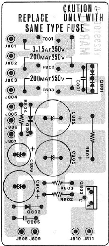
text_image
REPLACE SAINE TYPE FUSE ONLY WITH CAUTION J801 J802 J803 J804 J805 J806 J807 J808 J809 J810 J811 C801 C802 C803 C804 C805 Q801 Q802 Q803 Q804 Q805 Q806 + - + - + - + - R801 R802 R803 R804 R805 R806 R807 3.15AT250V 200MAT250V 200MAT250V 3.15AT250V F801 F802 F803 F804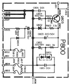
text_image
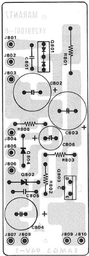
P800 126 15V 24V 10V 32V 10V 40V 10V 50V 10V 60V 10V 70V 10V 80V 10V 90V 10V 100V 10V 110V 10V 120V 10V 130V 10V 140V 10V 150V 10V 160V 10V 170V 10V 180V 10V 190V 10V 200V 10V 210V 10V 220V 10V 230V 10V 240V 10V 250V 10V 260V 10V 270V 10V 280V 10V 290V 10V 300V 10V 310V 10V 320V 10V 330V 10V 340V 10V 350V 10V 360V 10V 370V 10V 380V 10V 390V 10V 400V 10V 410V 10V 420V 10V 430V 10V 440V 10V 450V 10V 460V 10V 470V 10V 480V 10V 490V 10V 500V 10V 510V 10V 520V 10V 530V 10V 540V 10V 550V 10V 560V 10V 570V 10V 580V 10V 590V 10V 600V 10V 610V 10V 620V 10V 630V 10V 640V 10V 650V 10V 660V 10V 670V 10V 680V 10V 690V 10V 700V 10V 710V 10V 720V 10V 730V 10V 740V 10V 750V 10V 760V 10V 770V 10V 780V 10V 790V 10V 800V 10V 810W6.9 POWER SUPPLY BOARD SCHEMAIC DIAGRAM AND COMPONENT LOCATIONS - P800 - EUROPE
text_image
J807 J808 C804 + Q803 C B R803 R802 C806 Q804 Q805 Q806 + - Q804 Q805 Q806 + Q803 C803 C806 + Q801 R801 Q801 C801 Q801 J803 J802 J801 STARAM O-120195N/A f-Vap E O MA3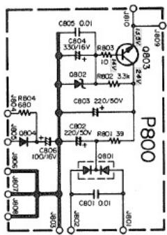
text_image
P800 108R 108R 908R 908R 100V C203 C204 C205 C206 C207 C208 C209 C210 C211 C212 C213 C214 C215 C216 C217 C218 C219 C220 C221 C222 C223 C224 C225 C226 C227 C228 C229 C230 C231 C232 C233 C234 C235 C236 C237 C238 C239 C240 C241 C242 C243 C244 C245 C246 C247 C248 C249 C250 C251 C252 C253 C254 C255 C256 C257 C258 C259 C260 C261 C262 C263 C264 C265 C266 C267 C268 C269 C270 C271 C272 C273 C274 C275 C276 C277 C278 C279 C280 D80B6.7 FRONT END BOARD SCHEMAIC DIAGRAM AND COMPONENT LOCATICINS - P100
6.8 POWER SUPPLY BOARD SCHEMAIC DIAGRAM AND COMPONENT LOCATIONS - P800 - U.S.A. & CANADA
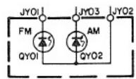
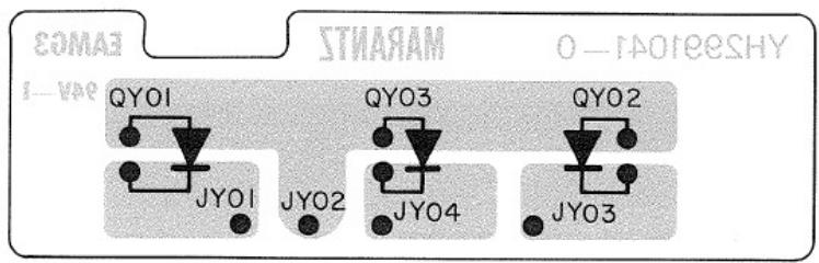
6.10 FUNCTION INDICATOR BOARD SCHEMATIC DIAGRAM AND COMPONENT LOCATIONS - PY01
text_image
SOMA3 STUARAM O-RAOESHY QY01 QY03 QY02 JY01 JY02 JY04 JY036.11 DIAL LAMP BOARD SCHEMATIC DIAGRAM AND COMPONENT LOCATIONS - PZ01
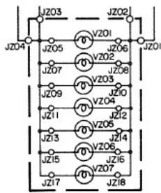
text_image
JZ03 JZ04 V201 JZ05 JZ06 JZ07 V202 JZ08 JZ09 V203 JZ10 JZ11 V204 JZ12 JZ13 V205 JZ14 JZ15 V206 JZ16 JZ17 V207 JZ18
text_image
MARANTZ Y62891001-0 RAMG3 94V-17. MAJOR COMPONENT LOCATIONS
7.1 CABINET - FRONT VIEW - U.S.A. & CANADA
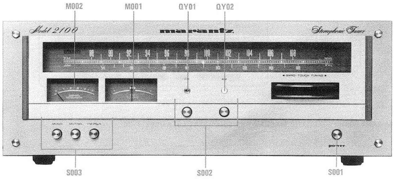
text_image
M002 M001 QY01 QY02 Model 2100 masero-amiz Stereophonic Tuner VDD 98 90 92 94 96 90 100 102 104 106 108 MAX KRC AVRO TOUCH TUNING AVRO S003 S002 S001 power7.2 CHASSIS - TOP VIEW - U.S.A. & CANADA
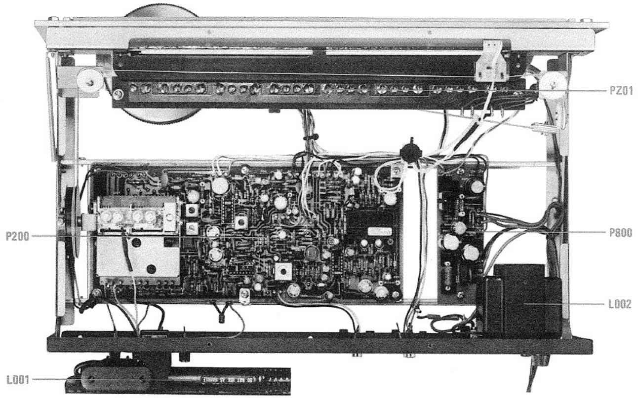
text_image
PZ01 P200 P800 L002 L0017.3 CABINET - REAR VIEW - U.S.A. & CANADA
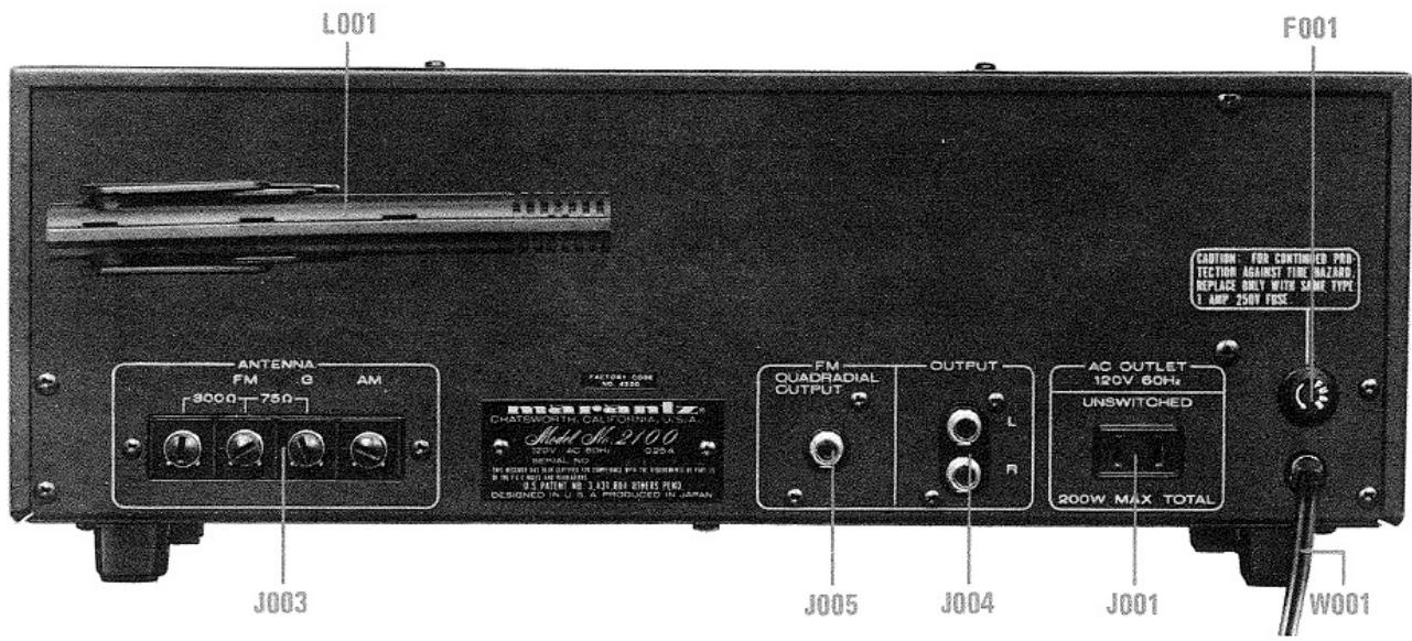
text_image
L001 F001 ANTENNA FM Q AM 9000 750 J003 FACTORY CORE MC 4255 EASTRA EYAMIZ CHATESWORTH CALIFONTIA, U.S.A. Audio No. 2100 120V AC 60Hz 520A W00A NO. AC OUTLET 120V 60Hz UNSWITCHED 200W MAX TOTAL J005 J004 J001 W001 CAUTION: FOR CONTINUED PROTECTION AGAINST TIME NAZARD; REPLACE ONLY WITH SOME TYPE I AMP 250V FUSE7.4 CHASSIS-BOTTOM VIEW-U.S.A.&CANADA
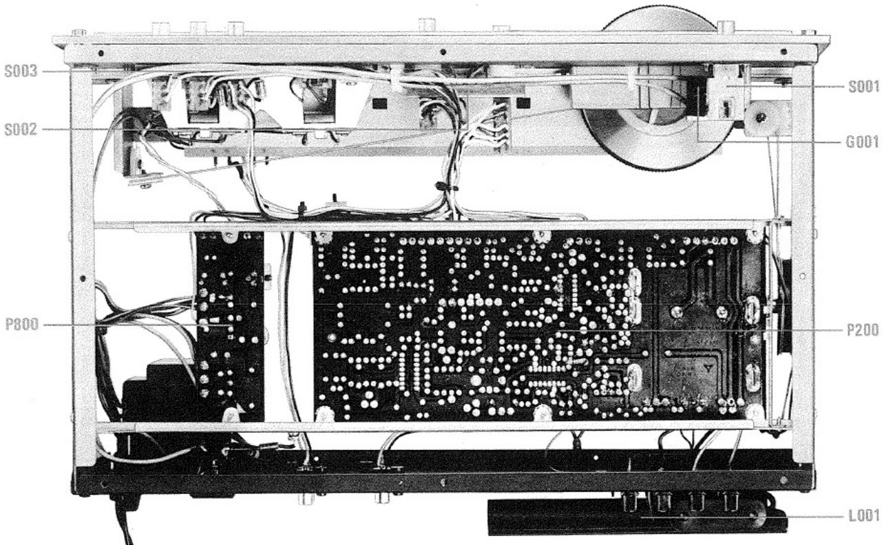
text_image
S003 S002 P800 S001 G001 P200 L0017.5 CABINET - FRONT VIEW - EUROPE
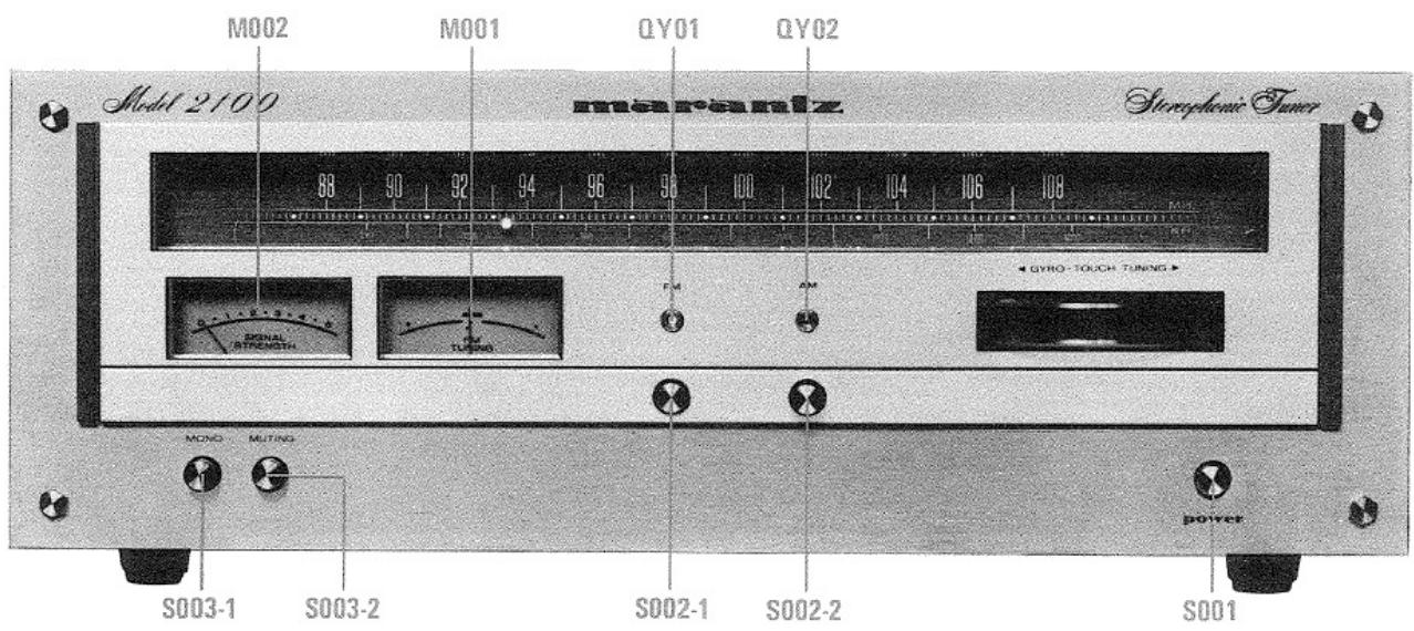
text_image
Model 2100 M002 M001 QY01 QY02 maserantz Storaphonic Tuner 88 90 92 94 96 98 100 102 104 106 108 HYRO-TOUCH TUNING S003-1 S003-2 S002-1 S002-2 S001 MONO MATING power7.6 CHASSIS - TOP VIEW - EUROPE
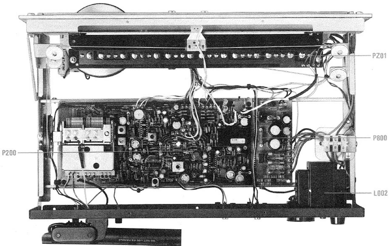
text_image
PZ01 P800 L002 P200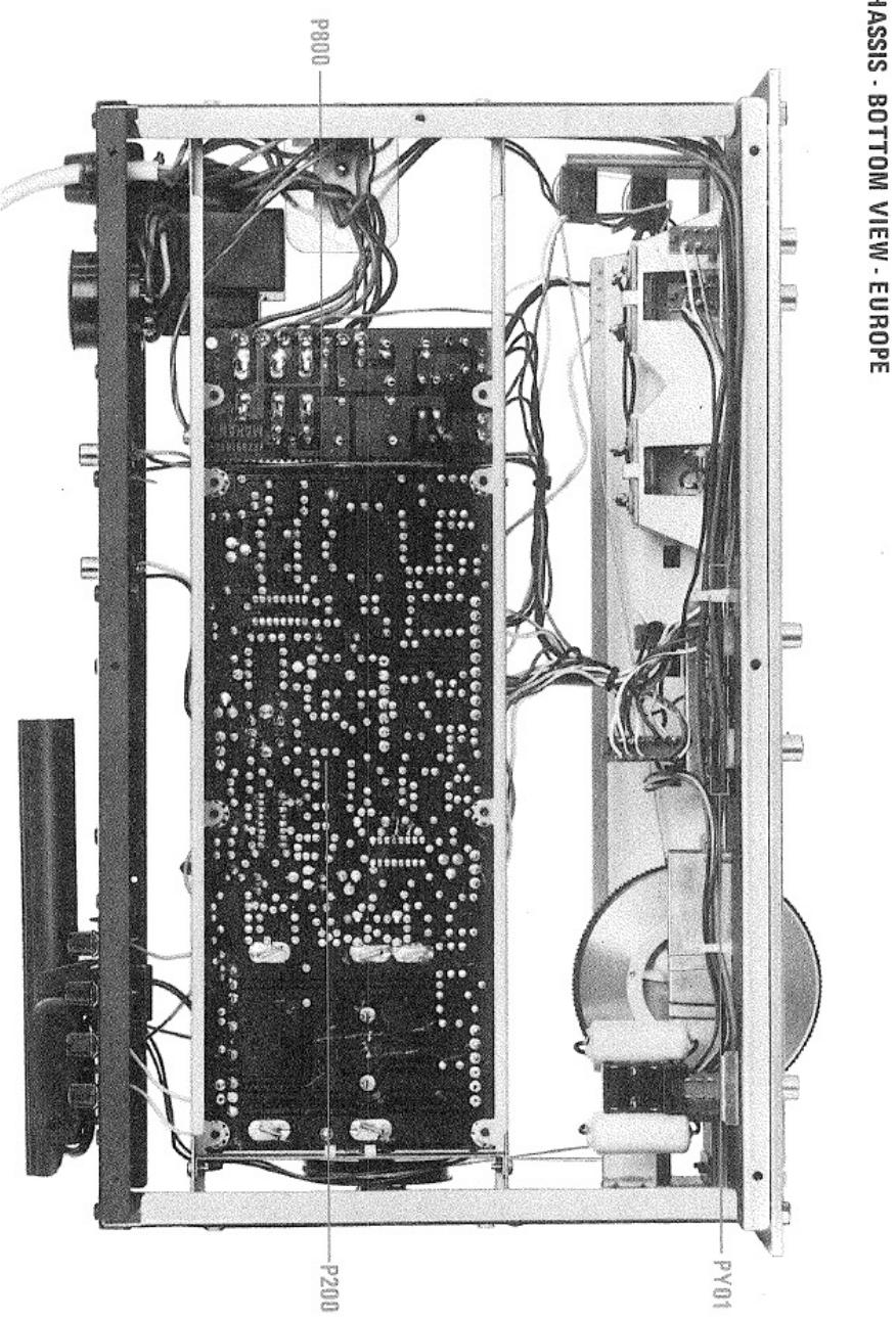
text_image
P200 P800 PY01 PASSIS · BOTTOM VIEW · EUROPE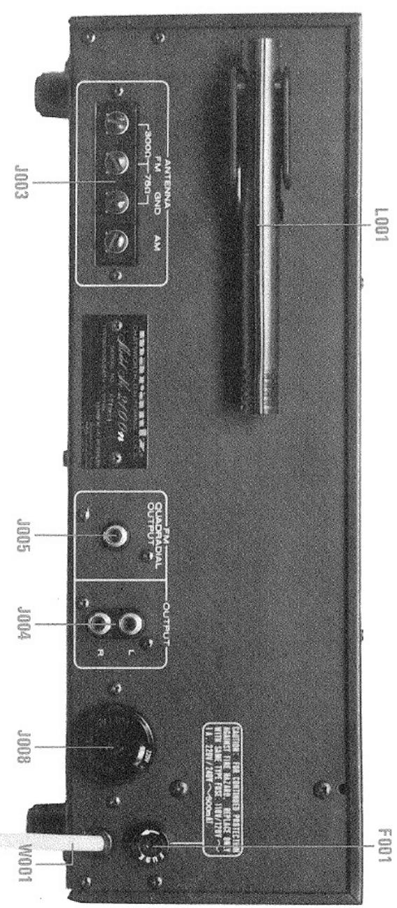
text_image
LOO1 FOO1 1001 2008 3009 4004 5005 6008 7009 8003 9004 1005 GMONOLK OUTPUT AMOUNTAL OUTRUN AMOUNTAL AMOUNTAL AMOUNTAL AMOUNTAL AMOUNTAL AMOUNTAL AMOUNTAL AMOUNTAL AMOUNTAL AMOUNTAL AMOUNTAL AMOUNTAL AMOUNTAL AMOUNTAL AMOUNTAL AMOUNTAL AMOUNTAL AMOUNTAL AMOUNTAL AMOUNTAL AMOUNTAL AMOUNTAL AMOUNTAL AMOUNTAL AMOUNTAL AMOUNTA AMOUNTA AMOUNTA AMOUNTA AMOUNTA AMOUNTA AMOUNTA AMOUNTA AMOUNTA AMOUNTA AMOUNTA AMOUNTA AMOUNTA AMOUNTA AMOUNTA AMOUNTA AMOUNTA AMOUNTA AMOUNTA AMOUNTA AMOUNTA AMOUNTA AMOUNTA AMOUNTA AMOUNTA AMOUNT A AMOUNT B AMOUNT C AMOUNT D AMOUNT E AMOUNT F AMOUNT G AMOUNT H AMOUNT I AMOUNT J AMOUNT K AMOUNT L AMOUNT M AMOUNT N AMOUNT O AMOUNT P AMOUNT Q AMOUNT R AMOUNT S AMOUNT T AMOUNT U AMOUNT V AMOUNT W AMOUNT X AMOUNT Y AMOUNT Z7.7 CABINET. REAR VIEW. EUROPE
- EXPLODED VIEWS
text_image
902S(E) 901S(U,C) 902S(C) 903V 003Y 004S 005S 001V 001S(U,C,E) 001S(U,C,E) 910S(E) 910S(E) 901S 909S 009S 015S 2231 004S 906S(C) 906S(C) 906S(E) 908S(U) 906S(E) 912S(C) 910S(U,C) 907S(U,C) 903S(E,C) 904S(U) 904S(C,E) 905S(U)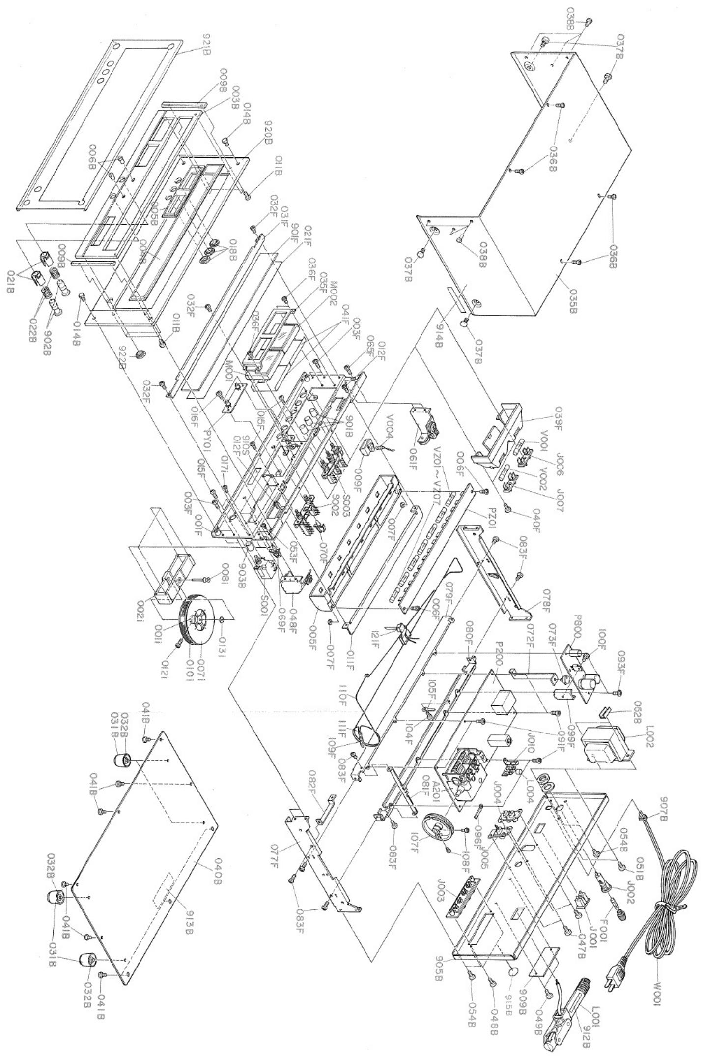
text_image
Exploded view diagram of a device assembly with numbered components and labeled parts in Chinese.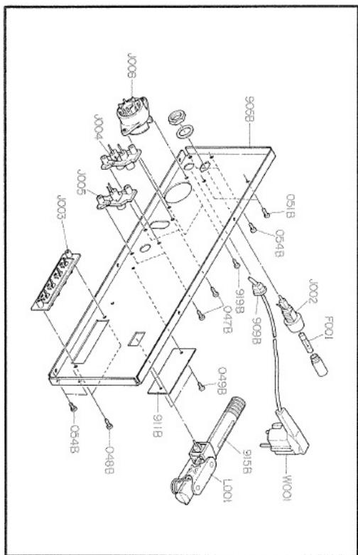
text_image
Technical diagram of a mechanical assembly with labeled components and part numbersEUROPEAN MODEL
- PARTS LIST
U: For U.S.A.
C: For Canada
E : For Europe
| REF. DESIG. | Q'TY | PART NO. | DESCRIPTION | ||
| U | C | E | |||
| A | 1 | 1 | 2991063400 | Front Panel Assembly | |
| A1 | 1 | 2991063410 | Front Panel Assembly | ||
| 003B | 1 | 1 | 1 | 2991063024 | Escutcheon |
| 004B | 1 | 1 | 1 | 2991158110 | Window |
| 005B | 1 | 1 | 1 | 2991158120 | Window |
| 006B | 2 | 2 | 2 | 2979259022 | Bushing |
| 009B | 2 | 2 | 2 | 2965063050 | Escutcheon |
| 011B | 9 | 9 | 9 | 51480306A9 | F. Washer Screw |
| 021B | 2 | 2 | 2 | 2979259012 | Bushing |
| 920B | 1 | 2991063013 | Escutcheon | ||
| 920B | 1 | 1 | 2991063110 | Escutcheon | |
| 921B | 1 | 2991053010 | Cover | ||
| 921B | 1 | 1 | 2991053110 | Cover | |
| 922B | 4 | 4 | 3 | 2978259010 | Bushing |
| B | 1 | 1 | 1 | 2219273400 | Flywheel Assembly |
| 001I | 1 | 1 | 1 | 2219273010 | Flywheel |
| 007I | 2 | 2 | 2 | 2219063030 | Escutcheon |
| 010I | 1 | 1 | 1 | 2219353010 | Ring |
| 0121 | 1 | 1 | 1 | 51820206B0 | P.H.M. Screw, P2x6 |
| C | 1 | 1 | 1 | 2991159400 | Drum Assembly |
| 107F | 1 | 1 | 1 | 2991159010 | Drum |
| 108F | 2 | 2 | 2 | 51064019A0 | P.H.M. Screw, P4x19 |
| 109F | 1 | 1 | 1 | 71101569M0 | Spring |
| MECHANICAL PARTS | |||||
| P208 | 12 | 12 | 12 | 2933118020 | Spacer |
| P211 | 13 | 13 | 13 | 75061251P0 | Jumper Wire |
| P808 | 5 | 5 | 5 | 2933118020 | Spacer |
| 001F | 1 | 1 | 1 | 2991160015 | Bracket |
| 001S | 1 | 1 | 1 | 2991801010 | Packing Case |
| 001V | 1 | 1 | 1 | ZA02000070 | External Antenna, FM |
| 002I | 1 | 1 | 1 | 2991104500 | Retainer |
| 002V | 1 | 1 | 1 | ZD00150160 | Connective Cord |
| 003F | 4 | 4 | 4 | 51280306B0 | B.H. Tapped Screw, B3x6ST |
| 003V | 1 | 1 | 1 | 9013025010 | Polyethylene Bag, Accessories |
| 004S | 2 | 2 | 2 | 2970809010 | Cushion |
| 005B | 1 | 1 | 1 | 2991158120 | Window |
| 005F | 1 | 1 | 1 | 2991274013 | Reflector |
| 005S | 1 | 1 | 1 | 9014335330 | Polyethylene Bag, Set |
| 006F | 2 | 2 | 2 | 51480308A9 | F. Washer Screw |
| 006S | 1 | 1 | 1 | 9013025010 | Polyethylene Bag, Printed Matter |
| 007F | 2 | 2 | 2 | 53110303E9 | Hexagon Nut |
| 008I | 1 | 1 | 1 | 2219112010 | Shaft |
| 009B | 2 | 2 | 2 | 2965063050 | Escutcheon |
| 009F | 1 | 1 | 1 | 2218274032 | Reflector |
| 009S | 1 | 1 | 1 | 2864804010 | Sleeve |
| 011F | 1 | 1 | 1 | 2991051012 | Guide |
| 012F | 2 | 2 | 2 | 51042608A0 | F.H.M. Screw, F2.6x8 |
| 013I | 1 | 1 | 1 | 59031405G9 | Washer |
| 014B | 4 | 4 | 4 | 52017069J0 | H. Head Bolt |
| 015F | 6 | 6 | 6 | 51100306A9 | B.H.M. Screw, B3x6 |
| 015S | 1 | 1 | 1 | 2819056010 | Buffer |
| 016F | 2 | 2 | 2 | 51280306B0 | B.H. Tapped Screw, B3x6ST |
| 017I | 4 | 4 | 4 | 51470306A9 | L. Washer Screw |
| 021F | 1 | 1 | 1 | 2991107010 | Sheet |
| REF. DESIG. | Q'TY | PART NO. | DESCRIPTION | ||
| U | C | E | |||
| 022B | 2 | 2 | 2 | 2979115012 | Spring |
| 031B | 4 | 4 | 4 | 2932057010 | Leg |
| 031F | 1 | 1 | 1 | 2991269015 | Protector |
| 032B | 4 | 4 | 4 | 51570410S9 | P. Tapped Screw, P4x10ST |
| 032F | 3 | 3 | 3 | 51280306B0 | B.H. Tapped Screw, B3x6ST |
| 035B | 1 | 1 | 1 | 2970257012 | Lid |
| 035F | 1 | 1 | 1 | 2991160053 | Bracket |
| 036B | 4 | 4 | 4 | 51280306U0 | B.H. Tapped Screw, B3x6ST |
| 036F | 4 | 4 | 4 | 51280306B0 | B.H. Tapped Screw, B3x6ST |
| 037B | 4 | 4 | 4 | 51480406S9 | F. Washer Screw |
| 038B | 6 | 6 | 6 | 2979259030 | Bushing |
| 039F | 1 | 1 | 1 | 2218274022 | Reflector |
| 040B | 1 | 1 | 1 | 2978257023 | Lid |
| 040F | 2 | 2 | 2 | 51280306B0 | B.H. Tapped Screw, B3x6ST |
| 041B | 8 | 8 | 8 | 51280408U0 | B.H. Tapped Screw, B4x8ST |
| 041F | 1 | 1 | 1 | 2991107020 | Sheet |
| 042F | 1 | 1 | 1 | 2991107020 | Sheet |
| 047B | 4 | 4 | 4 | 51280308U0 | B.H. Tapped Screw, B3x8ST |
| 048B | 2 | 2 | 2 | 51280308U0 | B.H. Tapped Screw, B3x8ST |
| 048F | 1 | 1 | 1 | 2991262503 | Pulley |
| 049B | 2 | 2 | 2 | 51280306U0 | B.H. Tapped Screw, B3x6ST |
| 051B | 2 | 2 | 2 | 51100408S9 | B.H.M. Screw, B4x8 |
| 052B | 2 | 2 | 2 | 2922005010 | Clamper |
| 053F | 2 | 2 | 2 | 51280306B0 | B.H. Tapped Screw, B3x6ST |
| 054B | 4 | 4 | 4 | 51280306U0 | B.H. Tapped Screw, B3x6ST |
| 061F | 1 | 1 | 1 | 2991262512 | Pulley |
| 065F | 2 | 2 | 2 | 51280306B0 | B.H. Tapped Screw, B3x6ST |
| 069F | 1 | 1 | 1 | 2886005060 | Clamper |
| 070F | 1 | 1 | 1 | 2886005050 | Clamper |
| 072F | 1 | 1 | 1 | 2991005010 | Clamper |
| 073F | 1 | 1 | 1 | 2908259010 | Bushing |
| 077F | 1 | 1 | 1 | 2991126014 | Stay |
| 078F | 1 | 1 | 1 | 2991126024 | Stay |
| 079F | 1 | 1 | 1 | 2991126033 | Stay |
| 080F | 1 | 1 | 1 | 2991126043 | Stay |
| 081F | 1 | 1 | 1 | 2991126050 | Stay |
| 082F | 1 | 1 | 1 | 2991126060 | Stay |
| 083F | 8 | 8 | 8 | 51280306B0 | B.H. Tapped Screw, B3x6ST |
| 091F | 6 | 6 | 6 | 51280306B0 | B.H. Tapped Screw, B3x6ST |
| 093F | 2 | 2 | 2 | 51280306B0 | B.H. Tapped Screw, B3x6ST |
| 096F | 1 | 1 | 1 | 1382005030 | Clamper |
| 099F | 1 | 1 | 1 | 2915267020 | Heatsink |
| 100F | 1 | 1 | 1 | 51100306A9 | B.H.M. Screw, B3x6 |
| 104F | 1 | 1 | 1 | 51280306B0 | B.H. Tapped Screw, B3x6ST |
| 105F | 1 | 1 | 1 | 62030039W0 | Lug |
| 109F | 1 | 1 | 1 | 71101569M0 | Spring |
| 110F | 2 | 2 | 2 | 72071605A0 | String |
| 111F | 2 | 2 | 2 | 56382540G0 | Eyelet |
| 121F | 1 | 1 | 1 | 2991103500 | Pointer |
| 135F | 1 | 1 | 1 | 2991109010 | Shield |
| 136F | 1 | 1 | 1 | 2991053110 | Cover |
| 901B | 3 | 3 | 4 | 2970154032 | Knob |
| 901F | 1 | 2991160090 | Bracket | ||
| 901F | 1 | 1 | 1 | 2991302013 | Dial |
| 901S | 3 | 9522815010 | Serial No. Card | ||
| 901S | 3 | 9523015120 | Serial No. Card | ||
| 901S | 1 | 9560000042 | Hang Tag | ||
| 902B | 2 | 2 | 2 | 2979154022 | Knob |
| 902F | 1 | 51280306B0 | B.H. Tapped Screw, B3x6ST | ||
| 902S | 2 | 9510901020 | Label | ||
| 902S | 3 | 9523015110 | Serial No. Card | ||
| 903B | 1 | 1 | 2963154030 | Knob | |
| 903S | 1 | 2818813010 | Envelope | ||
U: For U.S.A.
C: For Canada
E: For Europe
| REF. DESIG. | Q'TY | PART NO. | DESCRIPTION | ||
| U | C | E | |||
| 903S | 1 | 2918813012 | Envelope | ||
| 904F | 1 | 4113120010 | Insulator | ||
| 904S | 1 | 2577813010 | Envelope | ||
| 904S | 1 | 1 | 2818851120 | Instructions, Important | |
| 905B | 1 | 1 | 2991160213 | Bracket | |
| 905B | 1 | 2991160223 | Bracket | ||
| 905F | 2 | 51280314B0 | B.H. Tapped Screw, B3x14ST | ||
| 905S | 1 | 2577851020 | Instructions, Important | ||
| 905S | 1 | 1 | 9630000180 | Guarantee Card | |
| 906S | 1 | 2577854012 | Guarantee Card | ||
| 906S | 1 | 2818851140 | Instructions, Caution | ||
| 906S | 1 | 9650000050 | Service Station Card | ||
| 907B | 1 | 1 | 1455259030 | Bushing | |
| 907S | 1 | 2818854023 | Guarantee Card | ||
| 907S | 1 | 2818854042 | Guarantee Card | ||
| 908S | 1 | 2818851040 | Instructions, Caution | ||
| 908S | 1 | 2818854140 | Guarantee Card | ||
| 908S | 1 | 2991851310 | Instructions, Set | ||
| 909B | 1 | 1455259050 | Bushing | ||
| 909B | 1 | 2991265010 | Indicator | ||
| 909B | 1 | 2991265020 | Indicator | ||
| 910S | 1 | 2731821010 | Silicagel | ||
| 910S | 1 | 2991851010 | Instructions, Set | ||
| 910S | 1 | 2991851310 | Instructions, Set | ||
| 911B | 1 | 2991265082 | Indicator | ||
| 912B | 1 | 2506265060 | Indicator | ||
| 912B | 1 | 2911861170 | Label | ||
| 912S | 1 | 2886851100 | Instructions, Set | ||
| 913B | 1 | 2578861010 | Label | ||
| 913B | 1 | 2911861110 | Label | ||
| 914B | 1 | 2911861140 | Label | ||
| 914B | 1 | 2932861010 | Label | ||
| 915B | 1 | 2506265060 | Indicator | ||
| 915B | 1 | 9510911010 | Label | ||
| 915B | 1 | 9510911020 | Label | ||
| 916B | 1 | 2578861010 | Label | ||
| 916B | 1 | 9511101030 | Label | ||
| 917B | 1 | 2911861190 | Label | ||
| 917B | 1 | 2932861010 | Label | ||
| 917B | 1 | 2991861010 | Label | ||
| 918B | 1 | 2911861290 | Label | ||
| 919B | 2 | 51100308S9 | B.H.M. Screw, B3x8 | ||
| 923B | 1 | 2882861020 | Label | ||
| ELECTRICAL PARTS | |||||
| JY01 | 1 | 1 | 1 | YP10001130 | Plug |
| JY02 | 1 | 1 | 1 | YP10001130 | Plug |
| JY03 | 1 | 1 | 1 | YP10001130 | Plug |
| PY01 | 1 | 1 | 1 | YH29910410 | P.W. Board, Function Indicator |
| 1 | 1 | 1 | ZZ29910050 | P.W. Board Assembly | |
| QY01 | 1 | 1 | 1 | HI10004030 | L.E.D., FM |
| QY02 | 1 | 1 | 1 | HI10004030 | L.E.D., AM |
| JZ01 | 1 | 1 | 1 | YP10001130 | Plug |
| JZ02 | 1 | 1 | 1 | YP10001130 | Plug |
| JZ03 | 1 | 1 | 1 | YP10001130 | Plug |
| JZ04 | 1 | 1 | 1 | YP10001130 | Plug |
| JZ05 | 1 | 1 | 1 | YJ08000170 | Jack, Lamp Holder |
| JZ06 | 1 | 1 | 1 | YJ08000170 | Jack, Lamp Holder |
| JZ07 | 1 | 1 | 1 | YJ08000170 | Jack, Lamp Holder |
| JZ08 | 1 | 1 | 1 | YJ08000170 | Jack, Lamp Holder |
| JZ09 | 1 | 1 | 1 | YJ08000170 | Jack, Lamp Holder |
| REF. DESIG. | Q'TY | PART NO. | DESCRIPTION | ||
| U | C | E | |||
| JZ10 | 1 | 1 | 1 | YJ08000170 | Jack, Lamp Holder |
| JZ11 | 1 | 1 | 1 | YJ08000170 | Jack, Lamp Holder |
| JZ12 | 1 | 1 | 1 | YJ08000170 | Jack, Lamp Holder |
| JZ13 | 1 | 1 | 1 | YJ08000170 | Jack, Lamp Holder |
| JZ14 | 1 | 1 | 1 | YJ08000170 | Jack, Lamp Holder |
| JZ15 | 1 | 1 | 1 | YJ08000170 | Jack, Lamp Holder |
| JZ16 | 1 | 1 | 1 | YJ08000170 | Jack, Lamp Holder |
| JZ17 | 1 | 1 | 1 | YJ08000170 | Jack, Lamp Holder |
| JZ18 | 1 | 1 | 1 | YJ08000170 | Jack, Lamp Holder |
| PZ01 | 1 | 1 | 1 | YF29910010 | P.W. Board, Dial Lamp |
| 1 | 1 | 1 | ZZ29910040 | P.W. Board Assembly | |
| VZ01 | 1 | 1 | 1 | IN10080070 | Lamp, Dial, 8V 200mA |
| VZ02 | 1 | 1 | 1 | IN10080070 | Lamp, Dial, 8V 200mA |
| VZ03 | 1 | 1 | 1 | IN10080070 | Lamp, Dial, 8V 200mA |
| VZ04 | 1 | 1 | 1 | IN10080070 | Lamp, Dial, 8V 200mA |
| VZ05 | 1 | 1 | 1 | IN10080070 | Lamp, Dial, 8V 200mA |
| VZ06 | 1 | 1 | 1 | IN10080070 | Lamp, Dial, 8V 200mA |
| VZ07 | 1 | 1 | 1 | IN10080070 | Lamp, Dial, 8V 200mA |
| C001 | 1 | 1 | 1 | EA47601090 | Cap., Elect., 47μF, 10V |
| C002 | 1 | 1 | DF15222050 | Cap., Film, 2200pF | |
| C002 | 1 | DO07473540 | Cap., Oil-Paper, 0.047μF | ||
| C003 | 1 | 1 | DF15222050 | Cap., Film, 2200pF | |
| C003 | 1 | DO07473540 | Cap., Oil-Paper, 0.047μF | ||
| F001 | 1 | FS10050800 | Fuse, 250V 500mA, SEMKO | ||
| F001 | 1 | 1 | FS10100080 | Fuse, 250V 1A, UL | |
| G001 | 1 | BF10400040 | Printed Comp. | ||
| G001 | 1 | BF33300020 | Printed Comp. | ||
| J001 | 1 | 1 | YJ04000560 | Jack, AC Outlet | |
| J002 | 1 | 1 | YJ08000120 | Jack, Fuse Holder | |
| J002 | 1 | YJ08000220 | Jack, Fuse Holder | ||
| J003 | 1 | 1 | 1 | YT01040180 | Terminal, Antenna |
| J004 | 1 | 1 | 1 | YT02020140 | Terminal, Output |
| J005 | 1 | 1 | 1 | YT02010130 | Terminal, Quadradial Output |
| J006 | 1 | 1 | 1 | YJ08000190 | Jack, Meter Lamp Holder |
| J007 | 1 | 1 | 1 | YJ08000190 | Jack, Meter Lamp Holder |
| J008 | 1 | BY03110010 | Plug, Voltage Conversion | ||
| J009 | 1 | YL09030010 | Terminal, 3P | ||
| J010 | 1 | 1 | 1 | YL01030230 | Terminal, 3P Lug |
| L001 | 1 | 1 | 1 | LF11200520 | Antenna Coil, AM |
| L002 | 1 | 1 | TS16015050 | Power Transformer | |
| L002 | 1 | TS16015060 | Power Transformer | ||
| L003 | 1 | 1 | 1 | LC13320020 | Choke Coil, 3.3μH |
| L004 | 1 | 1 | 1 | LC11540020 | Choke Coil, 150μH |
| M001 | 1 | 1 | 1 | IM11055010 | Meter, FM Tuning |
| M002 | 1 | 1 | 1 | IM11055020 | Meter, Signal Strength |
| R001 | 1 | 1 | GT05225120 | Res., Fixed, 2.2MΩ ±5%, 1⁄2W | |
| S001 | 1 | 1 | SP01010180 | Pushswitch, Power | |
| S001 | 1 | SP04010250 | Pushswitch, Power | ||
| S002 | 1 | 1 | 1 | SP04020190 | Pushswitch, Selector |
| S003 | 1 | SP02020260 | Pushswitch, Mono/Muting | ||
| S003 | 1 | 1 | SP02030070 | Pushswitch, Mono/Muting/FM 25μS | |
| V001 | 1 | 1 | 1 | IN10080070 | Lamp, Meter, 8V 200mA |
| V002 | 1 | 1 | 1 | IN10080070 | Lamp, Meter, 8V 200mA |
| V003 | 1 | 1 | 1 | IN10080410 | Lamp, 8V 50mA |
| V004 | 1 | 1 | 1 | IN10080340 | Lamp, Stereo, 8V 60mA |
| W001 | 1 | YC01900030 | AC Power Cord | ||
| W001 | 1 | 1 | YC02400220 | AC Power Cord | |
| C101 | 1 | 1 | 1 | DD16120020 | Cap., Ceramic, 12pF |
| C102 | 1 | 1 | 1 | DK18203030 | Cap., Ceramic, 0.02μF |
| C103 | 1 | 1 | 1 | DK18203030 | Cap., Ceramic, 0.02μF |
| C104 | 1 | 1 | 1 | DD11020010 | Cap., Ceramic, 2pF |
U: For U.S.A.
C: For Canada
E : For Europe
| REF. DESIG. | Q'TY | PART NO. | DESCRIPTION | ||
| U | C | E | |||
| C105 | 1 | 1 | 1 | DK18203030 | Cap., Ceramic, 0.02μF |
| C106 | 1 | 1 | 1 | DD16150040 | Cap., Ceramic, 15pF |
| C107 | 1 | 1 | 1 | DD11020010 | Cap., Ceramic, 2pF |
| C108 | 1 | 1 | 1 | DD12050010 | Cap., Ceramic, 5pF |
| C109 | 1 | 1 | 1 | DD16101010 | Cap., Ceramic, 100pF |
| C110 | 1 | 1 | 1 | DK18203030 | Cap., Ceramic, 0.02μF |
| C111 | 1 | 1 | 1 | DD16101010 | Cap., Ceramic, 100pF |
| C112 | 1 | 1 | 1 | DK18203030 | Cap., Ceramic, 0.02μF |
| C113 | 1 | 1 | 1 | DD15150020 | Cap., Ceramic, 15pF |
| C114 | 1 | 1 | 1 | DD10050030 | Cap., Ceramic, 5pF |
| C115 | 1 | 1 | 1 | DD12050010 | Cap., Ceramic, 5pF |
| C116 | 1 | 1 | 1 | DD16330020 | Cap., Ceramic, 33pF |
| C117 | 1 | 1 | 1 | DD12100060 | Cap., Ceramic, 10pF |
| C118 | 1 | 1 | 1 | DK18203030 | Cap., Ceramic, 0.02μF |
| C119 | 1 | 1 | 1 | DD11020010 | Cap., Ceramic, 2pF |
| C120 | 1 | 1 | 1 | CA32400080 | Cap., Variable |
| C121 | 1 | 1 | 1 | CT14200010 | Cap., Trimmer |
| C151 | 1 | 1 | 1 | DK17103010 | Cap., Ceramic, 0.01μF |
| C152 | 1 | 1 | 1 | DK17103010 | Cap., Ceramic, 0.01μF |
| C153 | 1 | 1 | 1 | DK17102010 | Cap., Ceramic, 0.001μF |
| C154 | 1 | 1 | 1 | EA10701690 | Cap., Elect., 100μF, 16V |
| C155 | 1 | 1 | 1 | DK18403020 | Cap., Ceramic, 0.04μF |
| C156 | 1 | 1 | 1 | DF65391010 | Cap., Film, 390pF |
| C157 | 1 | 1 | 1 | DD16150010 | Cap., Ceramic, 15pF |
| C158 | 1 | 1 | 1 | DK18103010 | Cap., Ceramic, 0.01μF |
| C159 | 1 | 1 | 1 | DK17103010 | Cap., Ceramic, 0.01μF |
| C160 | 1 | 1 | 1 | DD16820010 | Cap., Ceramic, 82pF |
| C161 | 1 | 1 | 1 | DK17103010 | Cap., Ceramic, 0.01μF |
| C162 | 1 | 1 | 1 | DK18403020 | Cap., Ceramic, 0.04μF |
| C163 | 1 | 1 | 1 | EA10505090 | Cap., Elect., 1μF, 50V |
| C164 | 1 | 1 | 1 | EA22601690 | Cap., Elect., 22μF, 16V |
| C165 | 1 | 1 | 1 | EA47503590 | Cap., Elect., 4.7μF, 35V |
| C166 | 1 | 1 | 1 | DK17102010 | Cap., Ceramic, 0.001μF |
| C167 | 1 | 1 | 1 | DK18103010 | Cap., Ceramic, 0.01μF |
| C168 | 1 | 1 | 1 | DK16682010 | Cap., Ceramic, 0.0068μF |
| C169 | 1 | 1 | 1 | DK18403020 | Cap., Ceramic, 0.04μF |
| C170 | 1 | 1 | 1 | EA10701690 | Cap., Elect., 100μF, 16V |
| C171 | 1 | 1 | 1 | DF16104010 | Cap., Film, 0.1μF |
| C172 | 1 | 1 | 1 | EE47502510 | Cap., Elect., 4.7μF, 25V |
| F151 | 1 | 1 | 1 | FF10045160 | Ceramic Filter, AM, SFD455D |
| J101 | 1 | 1 | 1 | YP10001510 | Plug |
| J102 | 1 | 1 | 1 | YP10001510 | Plug |
| J103 | 1 | 1 | 1 | YP10001510 | Plug |
| J105 | 1 | 1 | 1 | YP10001510 | Plug |
| J107 | 1 | 1 | 1 | YP10001510 | Plug |
| J109 | 1 | 1 | 1 | YP10001510 | Plug |
| J110 | 1 | 1 | 1 | YP10001510 | Plug |
| J111 | 1 | 1 | 1 | YP10001510 | Plug |
| L105 | 1 | 1 | 1 | LC12220010 | Choke Coil |
| L106 | 1 | 1 | 1 | LI10239010 | IFT |
| L152 | 1 | 1 | 1 | LC13320020 | Choke Coil, 3.3μH |
| L153 | 1 | 1 | 1 | LC13320020 | Choke Coil, 3.3μH |
| L154 | 1 | 1 | 1 | LO10010480 | OSC Coil, AM |
| L155 | 1 | 1 | 1 | LI10015010 | IFT, AM |
| L156 | 1 | 1 | 1 | LI10015060 | IFT, AM |
| P100 | 1 | 1 | 1 | YD29910010 | P.W. Board, Front End |
| A201 | 1 | 1 | 1 | AV01202060 | Front End Assembly |
| Q101 | 1 | 1 | 1 | HF400451B0 | FET, 3SK45 B |
| Q102 | 1 | 1 | 1 | HT305352B0 | Transistor, 2SC535 B or C |
| Q103 | 1 | 1 | 1 | HT313422B0 | Transistor, 2SC1342 B or C |
| Q151 | 1 | 1 | 1 | HC10019010 | IC, HA1197 |
| Q152 | 1 | 1 | 1 | HT313272A0 | Transistor, 2SC1327 S or T |
| Q153 | 1 | 1 | 1 | HV00006120 | Varistor, MV-203 |
| REF. DESIG. | Q'TY | PART NO. | DESCRIPTION | ||
| U | C | E | |||
| R101 | 1 | 1 | 1 | GD05105140 | Res., Fixed, 1MΩ ±5%, 1⁄4W |
| R102 | 1 | 1 | 1 | GD05101140 | Res., Fixed, 100Ω ±5%, 1⁄4W |
| R103 | 1 | 1 | 1 | GD05101140 | Res., Fixed, 100Ω ±5%, 1⁄4W |
| R104 | 1 | 1 | 1 | GD05101140 | Res., Fixed, 100Ω ±5%, 1⁄4W |
| R105 | 1 | 1 | 1 | GD05223140 | Res., Fixed, 22kΩ ±5%, 1⁄4W |
| R106 | 1 | 1 | 1 | GD05472140 | Res., Fixed, 4.7kΩ ±5%, 1⁄4W |
| R107 | 1 | 1 | 1 | GD05102140 | Res., Fixed, 1kΩ ±5%, 1⁄4W |
| R108 | 1 | 1 | 1 | GD05103140 | Res., Fixed, 10kΩ ±5%, 1⁄4W |
| R109 | 1 | 1 | 1 | GD05332140 | Res., Fixed, 3.3kΩ ±5%, 1⁄4W |
| R110 | 1 | 1 | 1 | GD05103140 | Res., Fixed, 10kΩ ±5%, 1⁄4W |
| R111 | 1 | 1 | 1 | GD05101140 | Res., Fixed, 100Ω ±5%, 1⁄4W |
| R151 | 1 | 1 | 1 | RT05201140 | Res., Fixed, 200Ω ±5%, 1⁄4W |
| R152 | 1 | 1 | 1 | RT05152140 | Res., Fixed, 1.5kΩ ±5%, 1⁄4W |
| R153 | 1 | 1 | 1 | RT05202140 | Res., Fixed, 2kΩ ±5%, 1⁄4W |
| R154 | 1 | 1 | 1 | RT05152140 | Res., Fixed, 1.5kΩ ±5%, 1⁄4W |
| R155 | 1 | 1 | 1 | RT05151140 | Res., Fixed, 150Ω ±5%, 1⁄4W |
| R156 | 1 | 1 | 1 | RA05020200 | Res., Semifixed, 5kΩ |
| R157 | 1 | 1 | 1 | RT05391140 | Res., Fixed, 390Ω ±5%, 1⁄4W |
| R158 | 1 | 1 | 1 | RT05124140 | Res., Fixed, 120kΩ ±5%, 1⁄4W |
| R159 | 1 | 1 | 1 | RT05104140 | Res., Fixed, 100kΩ ±5%, 1⁄4W |
| R160 | 1 | 1 | 1 | RT05103140 | Res., Fixed, 10kΩ ±5%, 1⁄4W |
| R161 | 1 | 1 | 1 | RT05103140 | Res., Fixed, 10kΩ ±5%, 1⁄4W |
| R162 | 1 | 1 | 1 | RT05102140 | Res., Fixed, 1kΩ ±5%, 1⁄4W |
| R163 | 1 | 1 | 1 | RT05301140 | Res., Fixed, 300Ω ±5%, 1⁄4W |
| R164 | 1 | 1 | 1 | RT05473140 | Res., Fixed, 47kΩ ±5%, 1⁄4W |
| R165 | 1 | 1 | 1 | RT05104140 | Res., Fixed, 100kΩ ±5%, 1⁄4W |
| R166 | 1 | 1 | 1 | RT05152140 | Res., Fixed, 1.5kΩ ±5%, 1⁄4W |
| R167 | 1 | 1 | 1 | RT05242140 | Res., Fixed, 2.4kΩ ±5%, 1⁄4W |
| R169 | 1 | 1 | 1 | RT05473140 | Res., Fixed, 47kΩ ±5%, 1⁄4W |
| R170 | 1 | 1 | 1 | RT05101140 | Res., Fixed, 100Ω ±5%, 1⁄4W |
| C201 | 1 | 1 | 1 | DD15300010 | Cap., Ceramic, 30pF |
| C202 | 1 | 1 | 1 | DK17103010 | Cap., Ceramic, 0.01μF |
| C203 | 1 | 1 | 1 | DK17103010 | Cap., Ceramic, 0.01μF |
| C204 | 1 | 1 | 1 | DK17103010 | Cap., Ceramic, 0.01μF |
| C205 | 1 | 1 | 1 | DK18403020 | Cap., Ceramic, 0.04μF |
| C206 | 1 | 1 | 1 | DK18403020 | Cap., Ceramic, 0.04μF |
| C207 | 1 | 1 | 1 | DK18403020 | Cap., Ceramic, 0.04μF |
| C208 | 1 | 1 | 1 | EA47503590 | Cap., Elect., 4.7μF, 35V |
| C209 | 1 | 1 | 1 | DD15400040 | Cap., Ceramic, 40pF |
| C210 | 1 | 1 | 1 | EA22601690 | Cap., Elect., 22μF, 16V |
| C211 | 1 | 1 | 1 | EA47405010 | Cap., Elect., 0.47μF, 50V |
| C212 | 1 | 1 | 1 | DK18403010 | Cap., Ceramic, 0.04μF |
| C213 | 1 | 1 | 1 | DK18403010 | Cap., Ceramic, 0.04μF |
| C214 | 1 | 1 | 1 | DK18403010 | Cap., Ceramic, 0.04μF |
| C215 | 1 | 1 | 1 | DK18403010 | Cap., Ceramic, 0.04μF |
| C216 | 1 | 1 | 1 | DK18403010 | Cap., Ceramic, 0.04μF |
| C217 | 1 | 1 | 1 | EA10505090 | Cap., Elect., 1μF, 50V |
| C218 | 1 | 1 | 1 | EA10505090 | Cap., Elect., 1μF, 50V |
| F201 | 1 | 1 | 1 | FF11070050 | Ceramic Filter, SFE10.7MD1 |
| F202 | 1 | 1 | 1 | FF11070050 | Ceramic Filter, SFE10.7MD1 |
| F203 | 1 | 1 | 1 | FF11070050 | Ceramic Filter, SFE10.7MD1 |
| J201 | |||||
| J229 | 29 | 29 | 29 | YP10001130 | Plug |
| J231 | 1 | 1 | 1 | YP10001130 | Plug |
| L202 | 1 | 1 | 1 | LI14019010 | IFT, FM |
| L203 | 1 | 1 | 1 | LC11830010 | Choke Coil, 18μH |
| P200 | 1 | 1 | 1 | YD22042012 | P.W. Board, Tuner |
| 1 | 1 | ZZ29912010 | P.W. Board Assembly | ||
| 1 | ZZ29918010 | P.W. Board Assembly | |||
| Q201 | 1 | 1 | 1 | HT310471C0 | Transistor, 2SC1047 C |
| Q202 | 1 | 1 | 1 | HC10021010 | IC, HA1137W |
U: For U.S.A.
C: For Canada
E: For Europe
| REF. DESIG. | Q'TY | PART NO. | DESCRIPTION | ||
| U | C | E | |||
| Q203 | 1 | 1 | 1 | HD20011050 | Diode, 1S1555 |
| Q204 | 1 | 1 | 1 | HD20011050 | Diode, 1S1555 |
| Q205 | 1 | 1 | 1 | HD20011050 | Diode, 1S1555 |
| Q206 | 1 | 1 | 1 | HT308281D0 | Transistor, 2SC828 S |
| R201 | 1 | 1 | 1 | RT05151140 | Res., Fixed, 150Ω ±5%, 1⁄4W |
| R202 | 1 | 1 | 1 | RT05331140 | Res., Fixed, 330Ω ±5%, 1⁄4W |
| R203 | 1 | 1 | 1 | RT05153140 | Res., Fixed, 15kΩ ±5%, 1⁄4W |
| R204 | 1 | 1 | 1 | RT05202140 | Res., Fixed, 2kΩ ±5%, 1⁄4W |
| R205 | 1 | 1 | 1 | RT05331140 | Res., Fixed, 330Ω ±5%, 1⁄4W |
| R206 | 1 | 1 | 1 | RT05102140 | Res., Fixed, 1kΩ ±5%, 1⁄4W |
| R207 | 1 | 1 | 1 | RT05101140 | Res., Fixed, 100Ω ±5%, 1⁄4W |
| R208 | 1 | 1 | 1 | RT05334140 | Res., Fixed, 330kΩ±5%, 1⁄4W |
| R209 | 1 | 1 | 1 | RA05030120 | Res., Semifixed, 50kΩ (B) |
| R210 | 1 | 1 | 1 | RT05103140 | Res., Fixed, 10kΩ ±5%, 1⁄4W |
| R211 | 1 | 1 | 1 | RT05104140 | Res., Fixed, 100kΩ±5%, 1⁄4W |
| R212 | 1 | 1 | 1 | RA01030250 | Res., Semifixed, 10kΩ (B) |
| R213 | 1 | 1 | 1 | RT05123140 | Res., Fixed, 12kΩ ±5%, 1⁄4W |
| R214 | 1 | 1 | 1 | RT05331140 | Res., Fixed, 330Ω ±5%, 1⁄4W |
| R215 | 1 | 1 | 1 | RA05030120 | Res., Semifixed, 50kΩ (B) |
| R216 | 1 | 1 | 1 | RT05562140 | Res., Fixed, 5.6kΩ ±5%, 1⁄4W |
| R217 | 1 | 1 | 1 | RT05222140 | Res., Fixed, 2.2kΩ ±5%, 1⁄4W |
| R218 | 1 | 1 | 1 | RT05222140 | Res., Fixed, 2.2kΩ ±5%, 1⁄4W |
| R219 | 1 | 1 | 1 | RT05123140 | Res., Fixed, 12kΩ ±5%, 1⁄4W |
| R220 | 1 | 1 | 1 | RT05391140 | Res., Fixed, 390Ω ±5%, 1⁄4W |
| R221 | 1 | 1 | 1 | RT05223140 | Res., Fixed, 22kΩ ±5%, 1⁄4W |
| R222 | 1 | 1 | 1 | RT05473140 | Res., Fixed, 47kΩ ±5%, 1⁄4W |
| R223 | 1 | 1 | 1 | RT05470140 | Res., Fixed, 47Ω ±5%, 1⁄4W |
| R224 | 1 | 1 | 1 | RT05102140 | Res., Fixed, 1kΩ ±5%, 1⁄4W |
| C301 | 1 | 1 | 1 | EA47503590 | Cap., Elect., 4.7μF, 35V |
| C302 | 1 | 1 | 1 | DF65361500 | Cap., Film, 360pF |
| C303 | 1 | 1 | 1 | EA10701690 | Cap., Elect., 100μF, 16V |
| C304 | 1 | 1 | 1 | EE33502510 | Cap., Elect., 3.3μF, 25V |
| C305 | 1 | 1 | 1 | EE10505010 | Cap., Elect., 1μF, 50V |
| C306 | 1 | 1 | 1 | EA10505090 | Cap., Elect., 1μF, 50V |
| C307 | 1 | 1 | 1 | EQ22405010 | Cap., Elect., 0.22μF, 50V |
| C308 | 1 | 1 | 1 | DF17473010 | Cap., Film, 0.047μF |
| C309 | 1 | 1 | 1 | DD15500050 | Cap., Ceramic, 50pF |
| C310 | 1 | 1 | 1 | DD15500050 | Cap., Ceramic, 50pF |
| C311 | 1 | 1 | 1 | EA10601690 | Cap., Elect., 10μF, 16V |
| C312 | 1 | 1 | 1 | EA10601690 | Cap., Elect., 10μF, 16V |
| C313 | 1 | 1 | 1 | EA22505090 | Cap., Elect., 2.2μF, 50V |
| C314 | 1 | 1 | 1 | EA22505090 | Cap., Elect., 2.2μF, 50V |
| C315 | 1 | 1 | DF15102050 | Cap., Film, 1000pF | |
| C315 | 1 | DF15222050 | Cap., Film, 2200pF | ||
| C316 | 1 | 1 | DF15102050 | Cap., Film, 1000pF | |
| C316 | 1 | DF15222050 | Cap., Film, 2200pF | ||
| C317 | 1 | 1 | 1 | EA47405010 | Cap., Elect., 0.47μF, 50V |
| C318 | 1 | 1 | 1 | EA47405010 | Cap., Elect., 0.47μF, 50V |
| C319 | 1 | 1 | 1 | EE47502510 | Cap., Elect., 4.7μF, 25V |
| C320 | 1 | 1 | 1 | EE47502510 | Cap., Elect., 4.7μF, 25V |
| C321 | 1 | 1 | 1 | EA10701690 | Cap., Elect., 100μF, 16V |
| C322 | 1 | 1 | 1 | EE10601640 | Cap., Elect., 10μF, 16V |
| L301 | 1 | 1 | 1 | LS35025010 | MPX Coil |
| Q301 | 1 | 1 | 1 | HT308281D0 | Transistor, 2SC828 S |
| Q302 | 1 | 1 | 1 | HC10020010 | IC, HA1196 |
| Q303 | 1 | 1 | 1 | HT313441E0 | Transistor, 2SC1344 E |
| Q304 | 1 | 1 | 1 | HT313441E0 | Transistor, 2SC1344 E |
| R301 | 1 | 1 | 1 | RA01030310 | Res., Semifixed, 10kΩ (B) |
| R302 | 1 | 1 | 1 | RT05104140 | Res., Fixed, 100kΩ ±5%, 1⁄4W |
| R303 | 1 | 1 | 1 | RT05223140 | Res., Fixed, 22kΩ ±5%, 1⁄4W |
| R304 | 1 | 1 | 1 | RT05102140 | Res., Fixed, 1kΩ ±5%, 1⁄4W |
| R305 | 1 | 1 | 1 | RT05104140 | Res., Fixed, 100kΩ ±5%, 1⁄4W |
| R306 | 1 | 1 | 1 | RT05824140 | Res., Fixed, 820kΩ ±5%, 1⁄4W |
| REF. DESIG. | Q'TY | PART NO. | DESCRIPTION | ||
| U | C | E | |||
| R307 | 1 | 1 | 1 | RT05473140 | Res., Fixed, 47kΩ ±5%, 1⁄4W |
| R308 | 1 | 1 | 1 | RT05101140 | Res., Fixed, 100Ω ±5%, 1⁄4W |
| R309 | 1 | 1 | 1 | RT05154140 | Res., Fixed, 150kΩ ±5%, 1⁄4W |
| R310 | 1 | 1 | 1 | RT05223140 | Res., Fixed, 22kΩ ±5%, 1⁄4W |
| R311 | 1 | 1 | 1 | RT05272140 | Res., Fixed, 2.7kΩ ±5%, 1⁄4W |
| R312 | 1 | 1 | 1 | RT05101140 | Res., Fixed, 100Ω ±5%, 1⁄4W |
| R313 | 1 | 1 | 1 | RT05303140 | Res., Fixed, 30kΩ ±5%, 1⁄4W |
| R314 | 1 | 1 | 1 | RT05303140 | Res., Fixed, 30kΩ ±5%, 1⁄4W |
| R315 | 1 | 1 | 1 | RT05473140 | Res., Fixed, 47kΩ ±5%, 1⁄4W |
| R316 | 1 | 1 | 1 | RT05473140 | Res., Fixed, 47kΩ ±5%, 1⁄4W |
| R317 | 1 | 1 | 1 | RA05040080 | Res., Semifixed, 500kΩ (B) |
| R318 | 1 | 1 | 1 | RT05473140 | Res., Fixed, 47kΩ ±5%, 1⁄4W |
| R319 | 1 | 1 | 1 | RT05273140 | Res., Fixed, 27kΩ ±5%, 1⁄4W |
| R320 | 1 | 1 | 1 | RT05273140 | Res., Fixed, 27kΩ ±5%, 1⁄4W |
| R321 | 1 | 1 | 1 | RT05332140 | Res., Fixed, 3.3kΩ ±5%, 1⁄4W |
| R322 | 1 | 1 | 1 | RT05332140 | Res., Fixed, 3.3kΩ ±5%, 1⁄4W |
| R323 | 1 | 1 | 1 | RT05332140 | Res., Fixed, 3.3kΩ ±5%, 1⁄4W |
| R324 | 1 | 1 | 1 | RT05332140 | Res., Fixed, 3.3kΩ ±5%, 1⁄4W |
| R325 | 1 | 1 | 1 | RT05243140 | Res., Fixed, 24kΩ ±5%, 1⁄4W |
| R326 | 1 | 1 | 1 | RT05243140 | Res., Fixed, 24kΩ ±5%, 1⁄4W |
| R327 | 1 | 1 | 1 | RT05394140 | Res., Fixed, 390kΩ ±5%, 1⁄4W |
| R328 | 1 | 1 | 1 | RT05394140 | Res., Fixed, 390kΩ ±5%, 1⁄4W |
| R329 | 1 | 1 | 1 | RT05105140 | Res., Fixed, 1MΩ ±5%, 1⁄4W |
| R330 | 1 | 1 | 1 | RT05105140 | Res., Fixed, 1MΩ ±5%, 1⁄4W |
| R331 | 1 | 1 | 1 | RT05391140 | Res., Fixed, 390Ω ±5%, 1⁄4W |
| R332 | 1 | 1 | 1 | RT05391140 | Res., Fixed, 390Ω ±5%, 1⁄4W |
| R333 | 1 | 1 | 1 | RT05222140 | Res., Fixed, 2.2kΩ ±5%, 1⁄4W |
| R334 | 1 | 1 | 1 | RT05222140 | Res., Fixed, 2.2kΩ ±5%, 1⁄4W |
| R335 | 1 | 1 | 1 | RT05473140 | Res., Fixed, 47kΩ ±5%, 1⁄4W |
| R336 | 1 | 1 | 1 | RT05473140 | Res., Fixed, 47kΩ ±5%, 1⁄4W |
| R337 | 1 | 1 | 1 | RT05101140 | Res., Fixed, 100Ω ±5%, 1⁄4W |
| R338 | 1 | 1 | 1 | RT05101140 | Res., Fixed, 100Ω ±5%, 1⁄4W |
| R339 | 1 | 1 | 1 | RT05101140 | Res., Fixed, 100Ω ±5%, 1⁄4W |
| R340 | 1 | 1 | 1 | RT05201140 | Res., Fixed, 200Ω ±5%, 1⁄4W |
| C801 | 1 | 1 | 1 | DK18103510 | Cap., Ceramic, 0.01μF |
| C802 | 1 | 1 | 1 | EA22705090 | Cap., Elect., 220μF, 50V |
| C803 | 1 | 1 | 1 | EA22705090 | Cap., Elect., 220μF, 50V |
| C804 | 1 | 1 | 1 | EA33701690 | Cap., Elect., 330μF, 16V |
| C805 | 1 | 1 | 1 | DK18103510 | Cap., Ceramic, 0.01μF |
| C806 | 1 | 1 | 1 | EA10701690 | Cap., Elect., 100μF, 16V |
| F801 | 1 | FS10315800 | Fuse, 3.15AT, SEMKO | ||
| F802 | 1 | FS10020800 | Fuse, 200mAT, SEMKO | ||
| F803 | 1 | FS10020800 | Fuse, 200mAT, SEMKO | ||
| J801 | 1 | 1 | 1 | YP10001130 | Plug |
| J802 | 1 | 1 | 1 | YP10001130 | Plug |
| J803 | 1 | 1 | 1 | YP10001130 | Plug |
| J804 | 1 | 1 | 1 | YP10001130 | Plug |
| J805 | 1 | 1 | 1 | YP10001130 | Plug |
| J806 | 1 | 1 | 1 | YP10001130 | Plug |
| J807 | 1 | 1 | 1 | YP10001130 | Plug |
| J808 | 1 | 1 | 1 | YP10001130 | Plug |
| J809 | 1 | 1 | 1 | YP10001130 | Plug |
| J810 | 1 | 1 | 1 | YP10001130 | Plug |
| J811 | 1 | YP10001130 | Plug | ||
| J812 | 1 | YJ08000200 | Jack | ||
| J813 | 1 | YJ08000200 | Jack | ||
| J814 | 1 | YJ08000200 | Jack | ||
| J815 | 1 | YJ08000200 | Jack | ||
| J816 | 1 | YJ08000200 | Jack | ||
| J817 | 1 | YJ08000200 | Jack | ||
| P800 | 1 | 1 | YK29910610 | P.W. Board, Power Supply | |
| 1 | 1 | ZZ29910020 | P.W. Board Assembly | ||
| P800 | 1 | YK29910620 | P.W. Board, Power Supply | ||
U: For U.S.A.
C: For Canada
E: For Europe
| REF. DESIG. | Q'TY | PART NO. | DESCRIPTION | ||
| U | C | E | |||
| 1 | ZZ29918030 | P.W. Board Assembly | |||
| Q801 | 1 | 1 | 1 | HD20011030 | Diode, DS131-B |
| Q802 | 1 | 1 | 1 | HD30021090 | Zener, BZ-140 |
| Q803 | 1 | 1 | 1 | HT403131E0 | Transistor, 2SD313E |
| Q804 | 1 | 1 | 1 | HD20005010 | Diode, W06B |
| R801 | 1 | 1 | 1 | GJ05390020 | Res., Fixed, 39Ω ±5%, 2W |
| R802 | 1 | 1 | 1 | RT05332140 | Res., Fixed, 3.3kΩ ±5%, 1⁄4W |
| R803 | 1 | 1 | 1 | RT05100140 | Res. Fixed, 10Ω ±5%, 1⁄4W |
| R804 | 1 | 1 | 1 | RT05681140 | Res., Fixed, 680Ω ±5%, 1⁄4W |
10. TECHNICAL SPECIFICATIONS
FM TUNER SECTION:
Sensitivity
IHF Usable 10.3 dBf (1.8 μV)
IHF 50 dB Quieting (Mono) 13.2 dBf (2.5 μV)
(Stereo) 37.3 dBf (40 μV)
DIN Sensitivity (Mono, 26 dB S/N, 300 ohms input) 1.6 μV
(Stereo, 46 dB S/N, 300 ohms input) 50 μV
Quieting Slope (Mono)
RF Input for 30 dB Quieting 9.3 dBf (1.6 μV)
Quieting at:
20 dBf ( 5.5 μV) 58 dB
25 dBf ( 10 μV) 62 dB
40 dBf ( 55 μV) 70 dB
65 dBf (1000 μV) 74 dB
Quieting Slope (Stereo)
Quieting at:
30 dBf ( 17 μV) 42 dB
40 dBf ( 55 μV) 53 dB
50 dBf (173 μV) 58 dB
65 dBf (1000 μV) 65 dB
Distortion (Mono) at 65 dBf (1000 μV)
100 Hz 0.25%
1000 Hz 0.15%
6000 Hz 0.3%
Distortion (Stereo) at 65 dBf (1000 μV)
100 Hz 0.35%
1000 Hz 0.3%
6000 Hz 0.5%
Distortion (Mono and Stereo)
at 50 dB Quieting, 1000 Hz 0.6%
Hum and Noise
at 65 dBf (1000 μV) Mono 72 dB
Frequency Response
30 Hz to 15 kHz Mono ....+0.2, -1.5 dB Stereo ....+0.2, -1.5 dB
Capture Ratio
at 45 dBf (100 μV) 1.5 dB at 65 dBf (1000 μV) 1.0 dB
Alternate Channel Selectivity 70 dB
Spurious Response Rejection 90 dB
Image Response Rejection 60 dB
I.F. Rejection (Balanced) 80 dB
A.M. Suppression 50 dB
Stereo Separation
100 Hz 40 dB
1000 Hz 45 dB
10 kHz 40 dB
Subcarrier Rejection 60 dB
AM TUNER SECTION:
IHF Usable Sensitivity 15μV
Distortion (THD), 30% Modulation 0.5%
Signal-to-Noise Ratio 50 dB
Frequency Response (±3 dB) 40 Hz to 2.3 kHz
Alternate Channel Selectivity 46 dB
Image Rejection 45 dB
Spurious Response Rejection 60 dB
I.F. Rejection 40 dB
GENERAL:
Power Requirements 120 V AC, 60 Hz (U.S.A. and Canadian Versions)
220 V AC, 50 Hz (European Version)
(This unit can be converted by a qualified technician to operate on 110/120/240 V AC, 50/60 Hz.)
Power Consumption 23 W
Semiconductor Complement:
Integrated Circuits 3
Transistors 9
Diodes 7
Dual Gate MOSFET 1
Dimensions:
Panel Width 416 mm (16-3/8 inches)
Panel Height 146 mm (5-3/4 inches)
Depth 239 mm (9-3/8 inches)
Weight:
Unit alone 6.0 kg (13.2 lbs)
Packed for shipment 7.4 kg (16.3 lbs)

marantz
MARANTZ CO., INC. · P.O. BOX 577 · CHATSWORTH, CALIFORNIA · 91311
[NO TEXT]
A WHOLLY-OWNED SUBSIDIARY OF SUPERSCOPE INC., CHATSWORTH, CALIFORNIA · 91311
DOLBY is a trademark of Dolby Laboratories Inc.