
3MXM68M - Climatiseur multi-split DAIKIN - Notice d'utilisation et mode d'emploi gratuit
Retrouvez gratuitement la notice de l'appareil 3MXM68M DAIKIN au format PDF.
| Type de produit | Climatiseur multi-split - unité intérieure murale |
| Marque | DAIKIN |
| Modèle | 3MXM68M (unité intérieure compatible FVXS-F) |
| Dimensions (H x L x P) | 600 x 700 x 210 mm |
| Poids net | 14 kg |
| Poids emballé | 18 kg |
| Alimentation électrique | 220-240 V / 50 Hz / Monophasé |
| Réfrigérant | R-410A |
| Puissance de refroidissement (nominale) | 2.5 kW (FVXS25F) / 3.5 kW (FVXS35F) / 5.0 kW (FVXS50F) |
| Puissance de chauffage (nominale) | 2.8 kW (FVXS25F) / 4.0 kW (FVXS35F) / 5.8 kW (FVXS50F) |
| Débit d'air (refroidissement - haut) | 8.2 / 8.5 / 10.7 m³/min |
| Débit d'air (chauffage - haut) | 8.8 / 9.4 / 11.8 m³/min |
| Niveau sonore (refroidissement - silencieux) | 23 dBA (FVXS25F) / 24 dBA (FVXS35F) / 32 dBA (FVXS50F) |
| Niveau sonore (chauffage - silencieux) | 23 dBA (FVXS25F) / 24 dBA (FVXS35F) / 32 dBA (FVXS50F) |
| Fonctions | Auto refroidissement/chauffage, ventilateur seul, sec, puissant, nuit, écono, silencieux, oscillation verticale automatique |
| Minuterie | Minuterie hebdomadaire, arrêt automatique |
| Contrôle | Télécommande infrarouge (incluse), contrôle en ligne optionnel |
| Filtre | Filtre à air lavable, filtre à purification photocatalytique titane apatite |
| Options disponibles | Adaptateur de câblage, contrôle centralisé, contrôleur en ligne, interface DIII-net, passerelle KNX |
| Redémarrage automatique | Oui |
| Auto-diagnostic | Oui |
| Garantie | Selon conditions DAIKIN |
FOIRE AUX QUESTIONS - 3MXM68M DAIKIN
Questions des utilisateurs sur 3MXM68M DAIKIN
0 question sur cet appareil. Repondez a celles que vous connaissez ou posez la votre.
Poser une nouvelle question sur cet appareil
Téléchargez la notice de votre Climatiseur multi-split au format PDF gratuitement ! Retrouvez votre notice 3MXM68M - DAIKIN et reprennez votre appareil électronique en main. Sur cette page sont publiés tous les documents nécessaires à l'utilisation de votre appareil 3MXM68M de la marque DAIKIN.
MODE D'EMPLOI 3MXM68M DAIKIN
Air Conditioning
Technical Data
Floor standing unit
natural_image
Front view of a white D480 air conditioner unit with ventilation grilles and control panel (no visible text or symbols)EEDEN14-100
TABLE OF CONTENTS
FVXS-F
1 Features 2
2 Specifications 3
Technical Specifications 3
Electrical Specifications 4
3 Options 5
4 Dimensional drawings 6
5 Centre of gravity....7
6 Piping diagrams 8
7 Wiring diagrams 9
Wiring Diagrams - Single Phase 9
8 Sound data....10
Sound Pressure Spectrum - Cooling 10
Sound Pressure Spectrum - Heating 11
1 Features
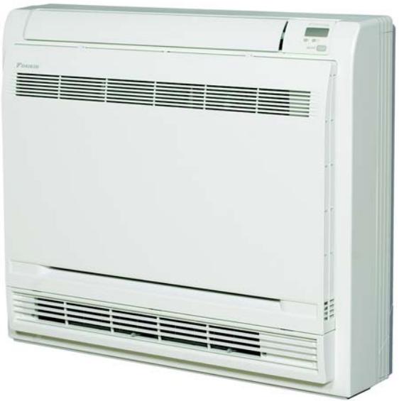
- Its low height enables the unit to fit perfectly beneath a window
- Can be installed against a wall or recessed
-
Vertical auto swing moves the discharge flaps up and down for efficient air and temperature distribution throughout the room
-
Online controller (optional): control your indoor unit from any location via smartphone, laptop, pc, tablet or touch screen
- Weekly timer can be set to start heating or cooling anytime on a daily or weekly basis
• Whisper quiet operation: down to 23dBA sound pressure level
1
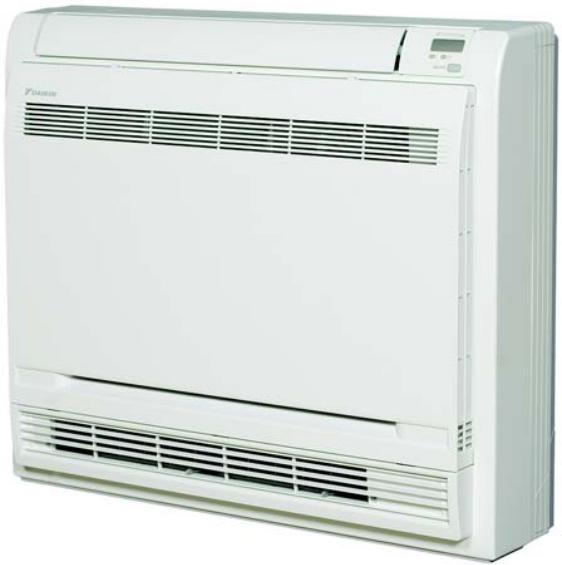
natural_image
Front view of a white Datasim air conditioner unit with ventilation grilles and control panel (no visible text or symbols)
Econo mode

Night set mode

Fan only

Powerful mode

Auto cooling-
heating
changeover

Whisper quiet

Indoor unit
silent operation

Vertical auto swing

Auto fan speed

Fan speed
steps

Dry programme Titanium apatite photocatalytic air purification filter

anium apatite
otocatalytic
purification
filter

Weekly timer

Infrared remote control

Auto-restart

Self diagnosis

Multi model application

VRV for residential application
2 Specifications
| 2-1 Technical Specifications | FVXS25F | FVXS35F | FVXS50F | ||||
| Power input - 50Hz | Cooling | Nom. | kW | 0.015 | 0.027 | ||
| Heating | Nom. | kW | 0.017 | 0.034 | |||
| Casing | Colour | White | |||||
| Dimensions | Unit | Height/Width/Depth | mm | 600/700/210 | |||
| Packed unit | Height/Width/Depth | mm | 696/786/286 | ||||
| Weight | Unit | kg | 14 | ||||
| Packed unit | kg | 18 | |||||
| Heat exchanger | Length | mm | 510 | ||||
| Rows | Quantity | 2 | |||||
| Fin pitch | mm | 1.2 | |||||
| Stages | Quantity | 22 | |||||
| Tube type | ø6.35 Hi-XU | ||||||
| Fin | Type | Multi slit fin | |||||
| Fan | Type | Turbo fan | |||||
| Quantity | - | 1 | |||||
| Air flow rate | Cooling | High | m3/min | 8.2 | 8.5 | 10.7 | |
| cfm | 290 | - | |||||
| Nom. | m3/min | 8.2 | 8.5 | 10.7 | |||
| cfm | 290 | - | |||||
| Low | m3/min | 4.8 | 4.9 | 7.8 | |||
| cfm | 169 | - | |||||
| Silent operation | m3/min | 4.1 | 4.5 | 6.6 | |||
| cfm | 145 | - | |||||
| Heating | High | m3/min | 8.8 | 9.4 | 11.8 | ||
| cfm | 311 | - | |||||
| Nom. | m3/min | 6.9 | 7.3 | 10.1 | |||
| cfm | 244 | - | |||||
| Low | m3/min | 5.0 | 5.2 | 8.5 | |||
| cfm | 177 | - | |||||
| Silent operation | m3/min | 4.4 | 4.7 | 7.1 | |||
| cfm | 155 | - | |||||
| Fan motor | Quantity | - | 1 | ||||
| Model | D48D-28 | ||||||
| Speed | Steps | 5 + silent, + auto | 5 | ||||
| Cooling | High/Medium/Low/Silent operation | rpm | 640/520/400/360 | 650/530/410/380 | 800/700/600/520 | ||
| Heating | High/Medium/Low/Silent operation | rpm | 680/550/420/380 | 700/560/420/390 | 850/740/630/540 | ||
| Output | High | W | 48 | ||||
| Sound power level | Cooling | dBA | 52 | 60 | |||
| Heating | dBA | 52 | 60 | ||||
| Sound pressure level | Cooling | High/Nom./Low/Silent operation | dBA | 38/32/26/23 | 39/33/27/24 | 44/40/36/32 | |
| Heating | Super high/High/Nom./Low/Silent operation | dBA | -/38/32/26/23 | -/39/33/27/24 | -/45/40/36/32 | ||
| Refrigerant | Type | R-410A | |||||
2 Specifications
| 2-1 Technical Specifications | FVXS25F | FVXS35F | FVXS50F | ||
| Piping connections | Liquid | OD | 6.35 | ||
| Gas | OD | 9.5 | 9.52 | 12.7 | |
| Drain | 20 | ||||
| Heat insulation | Both liquid and gas pipes | ||||
| Temperature control | Microcomputer control | ||||
| Air direction control | Right, Left, Horizontal, Downward | ||||
| Air filter | Type | Removable / washable / mildew proof | |||
Standard Accessories : Wireless remote control; Quantity : 1;
Standard Accessories : Air purification filter; Quantity : 2;
Standard Accessories : Batteries; Quantity : 2;
Standard Accessories : Remote control holder; Quantity : 1;
Standard Accessories : Thermal insulation tape; Quantity : 2;
Standard Accessories : Installation manual; Quantity : 1;
Standard Accessories : Drain hose; Quantity : 1;
Standard Accessories : Operation manual; Quantity : 1;
Standard Accessories : Air supply filter; Quantity : 1;
| 2-2 Electrical Specifications | FVXS25F | FVXS35F | FVXS50F | |||
| Power supply | Name | V1 | ||||
| Phase | 1~ | |||||
| Frequency | Hz | 50 | ||||
| Voltage | V | 220-240 | ||||
| Current | Nominal running current (RLA) - 50Hz | Cooling | A | 0.14 / 0.13 / 0.12 | 0.17 | |
| Heating | A | 0.15 / 0.14 / 0.13 | 0.19 | |||
| Current - 50Hz | Zmax | List | - | No requirements | ||
| Maximum running current | A | - | 0.20 | |||
| Wiring connections - 50Hz | For power supply | Quantity | - | 3 | ||
| Remark | 3 for power supply, 4 for interunit wiring (Earth wire included) | 4 for interunit wiring (earth wire included) | ||||
Notes
(1) 220V
(2) 230V
(3) 240V
(4) When connected with multi-system outdoor unit, refer to the specifications of the multi outdoor unit to be connected.
3 Options
3 - 1 Options
FVXS-F
Indoor Units - Control systems
| FVXS25F | FVXS35F | FVXS50F | ||
| Wiring adapter normal open contact / normal open pulse contact | KRP413A1S (1) | |||
| Centralised control board | Up to 5 rooms | KRC72 (2) | ||
| Central remote controller | DCS302C51 | |||
| Unified ON/OFF control | DCS301B51 | |||
| Schedule timer | DST301B51 | |||
| Interface adapter for DIII-net | KRP928A25 | |||
| Online controller | KKRP01A | |||
| External mounting kit for online controller | KKRPW01A | |||
| Wifi power cable for online controller | KKRPW01A | |||
| Touch LCD wall controller (3) | KBRC01A | |||
| Simple wall controller (3) | KBRC501A | |||
| KNX gateway | KJIC-DD | |||
(1) Wiring adapter supplied by Daikin. Time clock and other devices: to be purchased locally.
(2) Wiring adapter is also required for each indoor unit.
(3) Can only be used in combination with online controller KKBP01A.
(3) Can only be used in combination with on-line controllers. With off
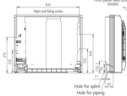
4 Dimensional drawings
4 - 1 Dimensional Drawings
FVXS25-35F
Note) 1. The mark ( ) shows piping direction
text_image
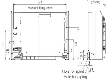
644 Main unit fixing screw 370 230 250 400 120, 5 90 17 82 Hole for splint Hole for piping Non-pulsed screw (inside)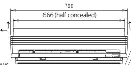

text_image
Model name label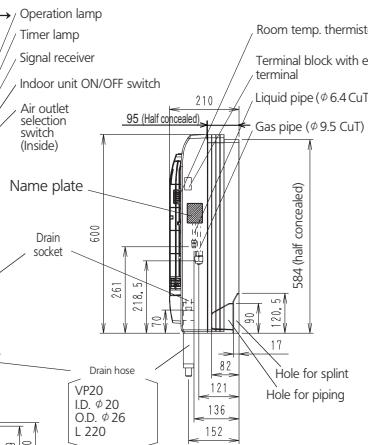
text_image
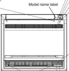
Operation lamp Timer lamp Signal receiver Indoor unit ON/OFF switch Air outlet selection switch (Inside) Name plate Drain socket 600 261 218.5 70 95 (Half concealed) 210 Room temp. thermist Terminal block with terminal Liquid pipe (φ 6.4 CuT) Gas pipe (φ 9.5 CuT) 584 (half concealed) 120, 5 90 17 82 121 136 152 Drain hose VP20 I.D. φ 20 O.D. φ 26 L 220 Hole for splint Hole for pipingunit (mm)
text_image
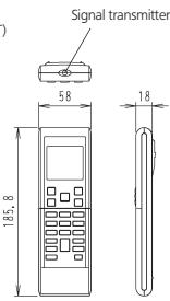
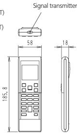
Signal transmitter 58 18 185, 8ARC452A1 Infrared remote control
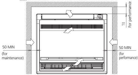
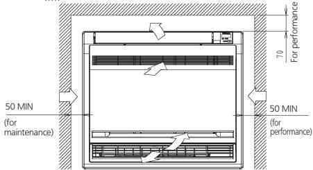
Air flow
Required space
text_image
50 MIN (for maintenance) 70 For performance 50 MIN (for performance)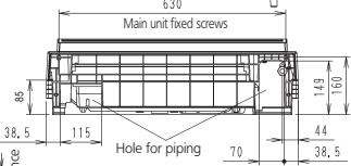
text_image
650 Main unit fixed screws 85 38, 5 115 Hole for piping 70 44 38, 5 14,9 160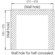
text_image
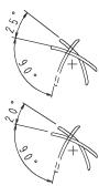
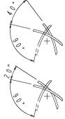
670~690 (Wall hole) 585~595 (Wall hole) Wall hole for half concealedAdjusting the air flow direction
Right/left (manual)
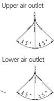
Up/down (automatic)
Cool, dry
Upward air flow limit (OFF)
Upward air flow limit (ON)
3D056135A
FVXS50F
Note) 1. The mark ( ) shows piping direction
text_image
644 Main unit fixing screw 370 230 250 400 (inside) 120.5 90 17 82 Hole for splint Hole for piping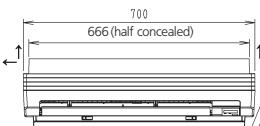
text_image
Model name label
text_image
Operation lamp Timer lamp Signal receiver Indoor unit ON/OFF switch Air outlet selection switch (Inside) Name plate Drain socket 600 261 218.5 70 95 (Half concealed) 210 Room temp. thermisto Terminal block with ea terminal Liquid pipe (φ6.4 CuT) Gas pipe (φ12.7 CuT) 584 (half concealed) 120, 5 17 82 121 136 152 Drain hose VP20 I.D. φ20 O.D. φ26 L 220 Hole for splint Hole for pipingunit (mm)
text_image
Signal transmitter 58 18 185, 8ARC452A1 Infrared remote control

text_image
50 MIN (for maintenance) 70 For performance 50 MIN (for performance)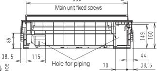
text_image
Main unit fixed screws 85 38, 5 115 Hole for piping 70 44 38, 5 149 160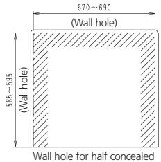
text_image
670~690 (Wall hole) 585~595 (Wall hole) Wall hole for half concealedAdjusting the air flow direction
Right/left (manual)

Lower air outlet

Up/down (automatic) Cool dry
Cool, dry


Heat
(Heat pump model)


3D056136A
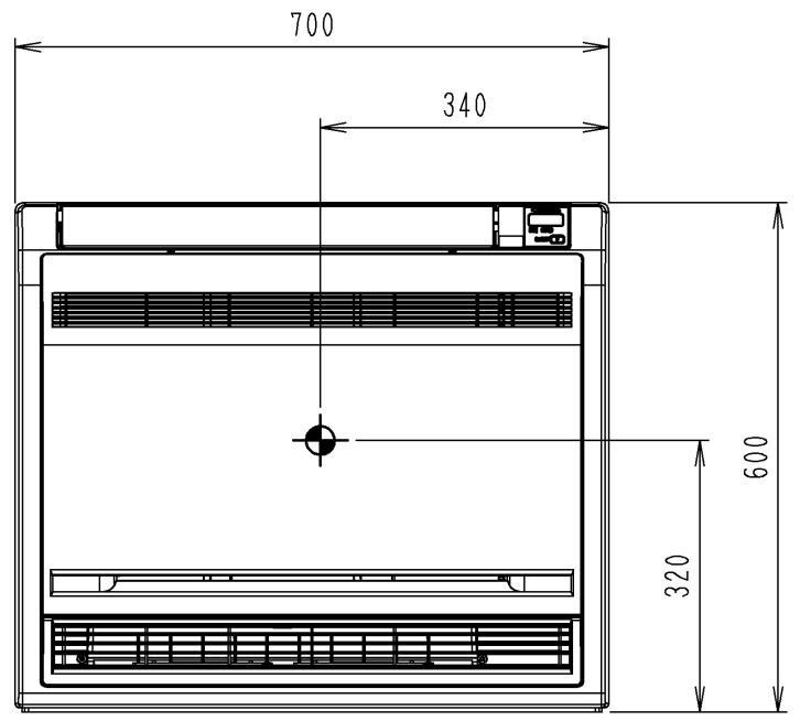
5 Centre of gravity
5 - 1 Centre of Gravity
FVXS-F
text_image
700 340 600 320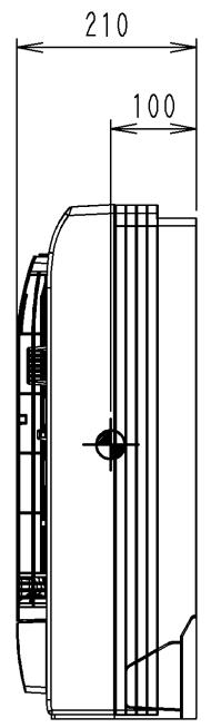
text_image
210 1004D056197D
6 Piping diagrams
6 - 1 Piping Diagrams
6
FVXS25-35F
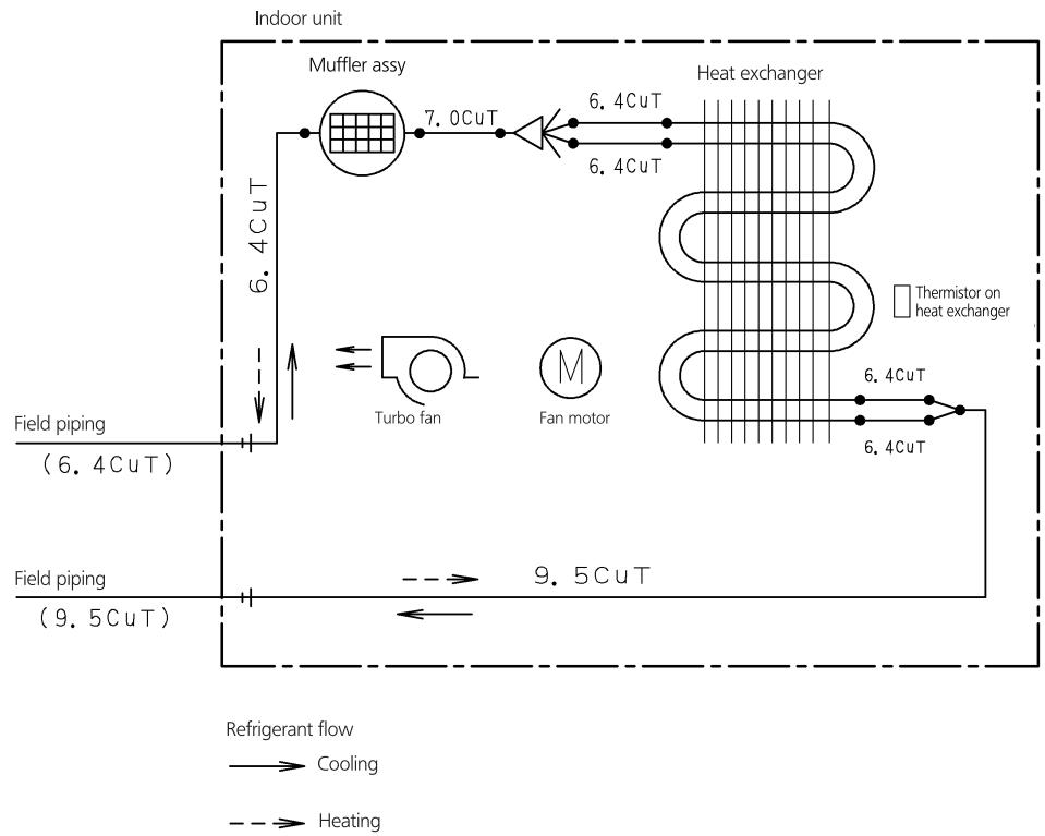
flowchart
graph TD
    A["Indoor unit"] --> B["Muffler assy"]
    B --> C["6.4CuT"]
    C --> D["Heat exchanger"]
    D --> E["6.4CuT"]
    E --> F["Turbo fan"]
    F --> G["Fan motor"]
    G --> H["9.5CuT"]
    H --> I["Field piping (9.5CuT)"]
    I --> J["Field piping (6.4CuT)"]
    J --> K["Refrigerant flow"]
    style A fill:#f9f,stroke:#333
    style K fill:#ccf,stroke:#333
4D056137B
FVXS50F
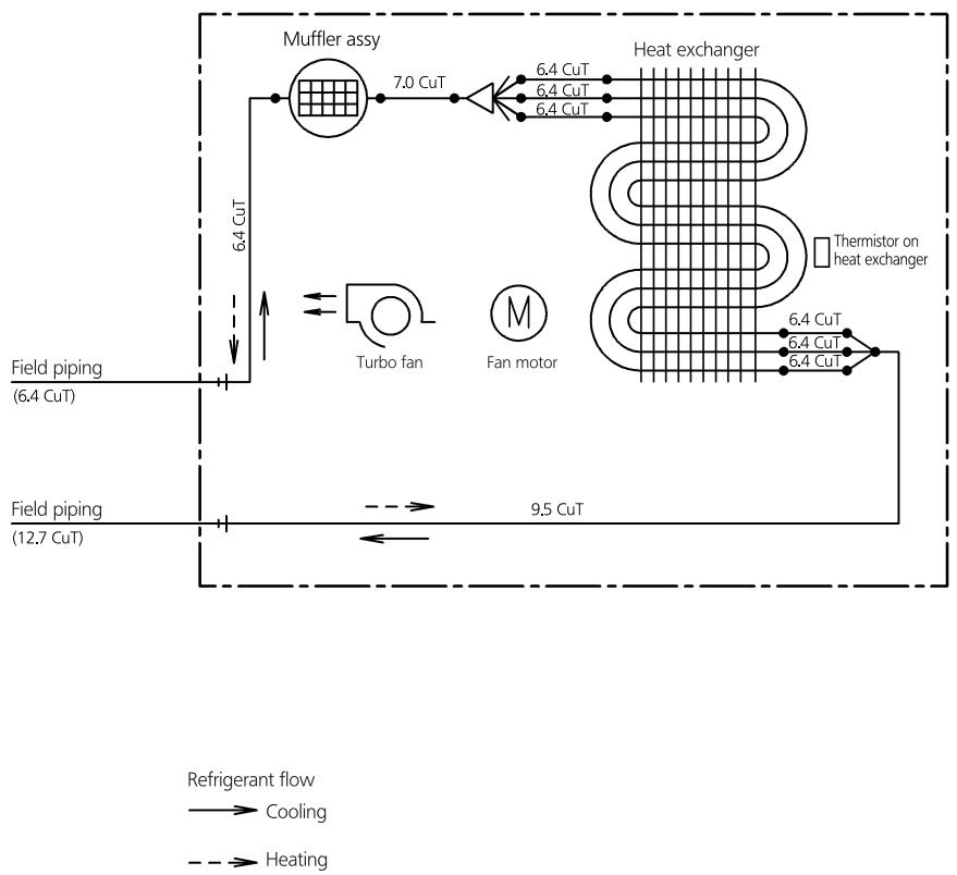
flowchart
graph TD
    A["Field piping (6.4 CuT)"] --> B["Muffler assy"]
    C["Field piping (12.7 CuT)"] --> D["Turbo fan"]
    D --> E["Fan motor"]
    E --> F["Heat exchanger"]
    F --> G["Thermistor on heat exchanger"]
    B --> H["7.0 CuT"]
    H --> I["6.4 CuT"]
    I --> J["6.4 CuT"]
    J --> K["6.4 CuT"]
    K --> L["6.4 CuT"]
    L --> M["9.5 CuT"]
    M --> N["Refrigerant flow"]
    style A fill:#f9f,stroke:#333
    style C fill:#f9f,stroke:#333
    style D fill:#ccf,stroke:#333
    style E fill:#cfc,stroke:#333
    style F fill:#fcc,stroke:#333
    style G fill:#cff,stroke:#333
    style H fill:#ffc,stroke:#333
    style I fill:#ffc,stroke:#333
    style J fill:#ffc,stroke:#333
    style K fill:#ffc,stroke:#333
    style L fill:#ffc,stroke:#333
    style M fill:#ffc,stroke:#333
    style N fill:#ffc,stroke:#333
4D056138D
7 Wiring diagrams
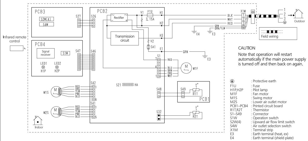
7 - 1 Wiring Diagrams - Single Phase
FVXS25-50F
text_image
Infrared remote control PCB3 S2W(4) S4W S27 S26 Rectifier V1 F1U H1 3.15A Transmission circuit H2 Z V2 SA1 E1 GRN E3 X1M BLK WHT RED GRN GRN/YLW Field wiring 1 2 3 Outdoor CAUTION Note that operation will restart automatically if the main power supply is turned off and then back on again. S48 S49 R1T PCB1 S32 R2T S21 HA S42 S41 S40 S39 S38 S37 S36 S35 S34 S33 S32 S31 S30 S29 S28 S27 S26 S25 S24 S23 S22 S21 Indoor M1S M1P LED1 LED2 H1P H2P M1S M2S M2S Indoor3D055953A
8 Sound data
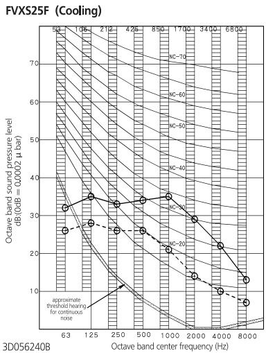
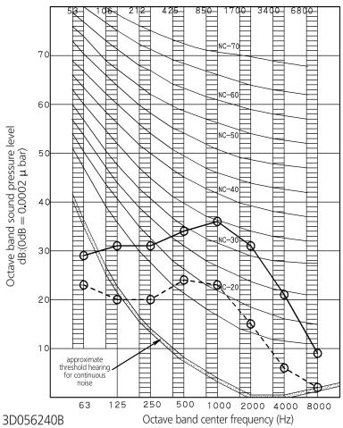
8 - 1 Sound Pressure Spectrum - Cooling
line
| Octave band center frequency (Hz) | Octave band sound pressure level (dB, dB = 0.0002 μ bar) | | ---------------------------------- | ------------------------------------------------------ | | 63 | 32 | | 125 | 34 | | 250 | 33 | | 500 | 32 | | 1000 | 34 | | 2000 | 30 | | 4000 | 22 | | 8000 | 14 || Scale | 50Hz230V(H) | 50Hz230V(L) | |
| A | 38 | 26 | |
| 1 Overall (dB):(B,G,N is already rectified) | |||
| 2 Measuring place: Measured in an anechoic room | |||
| 3 Operation noise differs with operation and ambient conditions. | |||
| 4 Operating conditions: Power source 220-240V, 50HzStandard external static pressure○—○ 50Hz 220-240v (H) ○----○ 50Hz 220-240V (L) | |||
| Scale | 50Hz230V(H) | 50Hz230V(L) |
| A | 38 | 26 |
line
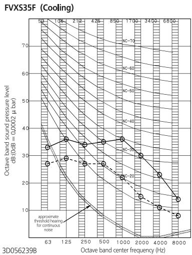
| Octave band center frequency (Hz) | Octave band sound pressure level dB(0 dB = 0.0002 μ bar) | | ---------------------------------- | -------------------------------------------------------- | | 63 | 35 | | 125 | 30 | | 250 | 28 | | 500 | 25 | | 1000 | 22 | | 2000 | 20 | | 4000 | 15 | | 8000 | 10 || Scale | 50Hz230V(H) | 50Hz230V(L) | |
| A | 39 | 27 | |
| 1 Overall (dB):(B,G,N is already rectified) | |||
| 2 Measuring place: Measured in an anechoic room | |||
| 3 Operation noise differs with operation and ambient conditions. | |||
| 4 Operating conditions: Power source 220-240V, 50HzStandard external static pressure○—○ 50Hz 220-240V (H) ○----○ 50Hz 220-240V (L) | |||
| 5 Location of microphone.JISC9612The operation noise measuringmethod is in accordance with JISC9612 | |||
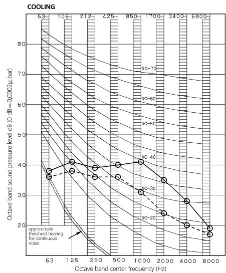
FVXS50F
line
| Octave band center frequency (Hz) | Octave band sound pressure level dB (0 dB=0.0002μ bar) | | --------------------------------- | ------------------------------------------------------ | | 63 | 85 | | 125 | 75 | | 250 | 65 | | 500 | 55 | | 1000 | 45 | | 2000 | 35 | | 4000 | 25 | | 8000 | 15 |NOTES
- Overall (dB)
| Scale | 50Hz230V (H) | 50Hz230V (L) |
| A | 44 | 36 |
(B,G,N is already rectified)
2 Measuring place: Measure in anechoic room
3 Operation noise differs with operation and ambient conditions.
4 Operating conditions: Power source 220-240V 50Hz JIS Standard
5 Standard external static pressure
○——○ 50 Hz 220-240V (H)
○----○ 50 Hz 220-240V (L)
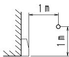
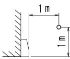
6 Location of microphone
JISC9612
The operation noise measuring method is in accordance with JISC9612
3D056238C
8 Sound data
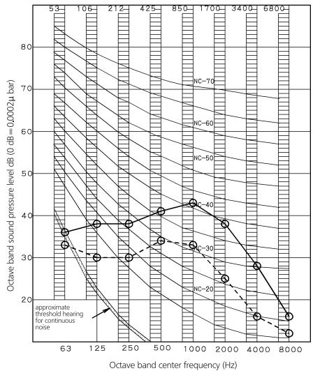
8 - 2 Sound Pressure Spectrum - Heating
FVXS25F (Heating)
line
| Octave band center frequency (Hz) | dB(dB=0.0002 μ bar) | | --------------------------------- | --------------------- | | 63 | 30 | | 125 | 25 | | 250 | 20 | | 500 | 15 | | 1000 | 10 | | 2000 | 5 | | 4000 | 2 | | 8000 | 1 |NOTES
1 Overall (dB):
(B,G,N is already rectified)
2 Measuring place: Measured in an anechoic room
3 Operation noise differs with operation and ambient conditions.
- Operating conditions: Power source 220-240V, 50Hz
Standard external static pressure
○—○ 50Hz 220-240v (H) ○---○ 50Hz 220-240V (L)
5 Location of microphone,
JISC9612
The operation noise measuring
method is in accordance with JISC9612
| Scale | 50Hz230V(H) | 50Hz230V(L) |
| A | 38 | 26 |

FVXS50F
HEATING
line
| Octave band center frequency (Hz) | Octave band sound pressure level dB (0 dB=0.0002μ bar) | | ---------------------------------- | ------------------------------------------------------ | | 63 | 35 | | 125 | 38 | | 250 | 39 | | 500 | 42 | | 1000 | 44 | | 2000 | 38 | | 4000 | 28 | | 8000 | 18 |NOTES
1 Overall (dB)
| Scale | 50Hz230V (H) | 50Hz230V (L) |
| A | 45 | 36 |
(B,G,N is already rectified)
2 Measuring place: Measure in anechoic room
3 Operation noise differs with operation and ambient conditions.
4 Operating conditions: Power source 220-240V 50Hz
JIS Standard
5 Standard external static pressure
50 Hz 220-240V (H) 50 Hz 220-240V (L)
Heating
6 Location of microphone
JSC9612 The operation noise measuring method is in accordance with JSC9612
3D056238C
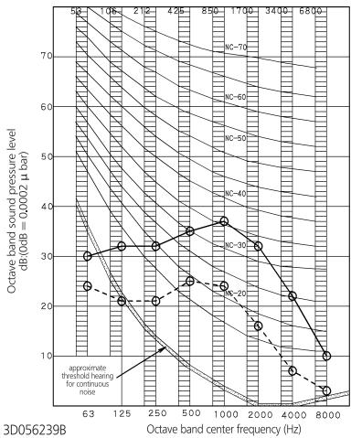
FVXS35F (Heating)
line
| Octave band center frequency (Hz) | Octave band sound pressure level dB(0dB = 0.0002 μ bar) | | ---------------------------------- | ------------------------------------------------------ | | 63 | 30 | | 125 | 32 | | 250 | 34 | | 500 | 36 | | 1000 | 38 | | 2000 | 36 | | 4000 | 32 | | 8000 | 10 |NOTES
1 Overall (dB):
(B,G,N is already rectified)
2 Measuring place: Measured in an anechoic room
3 Operation noise differs with operation and ambient conditions.
- Operating conditions: Power source 220-240V, 50Hz
Standard external static pressure
○——○ 50Hz 220-240v (H) ○---○ 50Hz 220-240V (L)
5 Location of microphone.
JISC9612
The operation noise measuring
method is in accordance with JISC9612
| Scale | 50Hz230V(H) | 50Hz230V(L) |
| A | 39 | 27 |


Daikin Europe N.V. participates in the Eurovent Certification programme for Liquid Chilling Packages (LCP), Air handling units (AHU) and Fan coil units (FCU), Check ongoing validity of certificate online: www.eurovent-certification.com or using: www.certiflash.com
The present leaflet is drawn up by way of information only and does not constitute an offer binding upon Daikin Europe N.V.. Daikin Europe N.V. has compiled the content of this leaflet to the best of its knowledge. No express or implied warranty is given for the completeness, accuracy, reliability or fitness for particular purpose of its content and the products and services presented therein. Specifications are subject to change without prior notice. Daikin Europe N.V. explicitly rejects any liability for any direct or indirect damage, in the broadest sense, arising from or related to the use and/or interpretation of this leaflet. All content is copyrighted by Daikin Europe N.V.
BARCODE
Daikin products are distributed by: