MODE D'EMPLOI T-93L KENWOOD
KT-2001
SOLID STATE AM-FM STEREO TUNER
INSTRUCTION MANUAL

To the New KT-2001 Tuner Owner:
Because Kenwood Electronics, Inc., takes great pride in the long tradition of quality components the name Kenwood represents, your purchase of a Kenwood tuner places you in a distinguished family of connoisseurs of superb high-fidelity sound reproduction.
The purpose of this manual is to acquaint you with the operating features of your new tuner. You will notice that in every detail of planning, engineering styling, operating convenience, and adaptability, we have sought to anticipate your needs and desires.
We suggest that you read this manual carefully. Knowing how to set up your tuner to best advantage will enhance your listening pleasure right from the start. You will also become aware of the ease with which you can adjust your tuner to meet your special requirements.
Turn the pages and become acquainted with the exciting features of your new tunes features that will remain new for endless hours of listening pleasure.
WARRANTY REGISTRATION
IMPORTANT: Fill out your warranty registration and mail it at once.
TABLE OF CONTENTS
INTRODUCTION 2
SPECIAL KT-2001 FEATURES 3
INTERCONNECTING DIAGRAM 4
CONNECTING ASSOCIATED COMPONENTS 5
ELECTRICAL CONNECTIONS 6
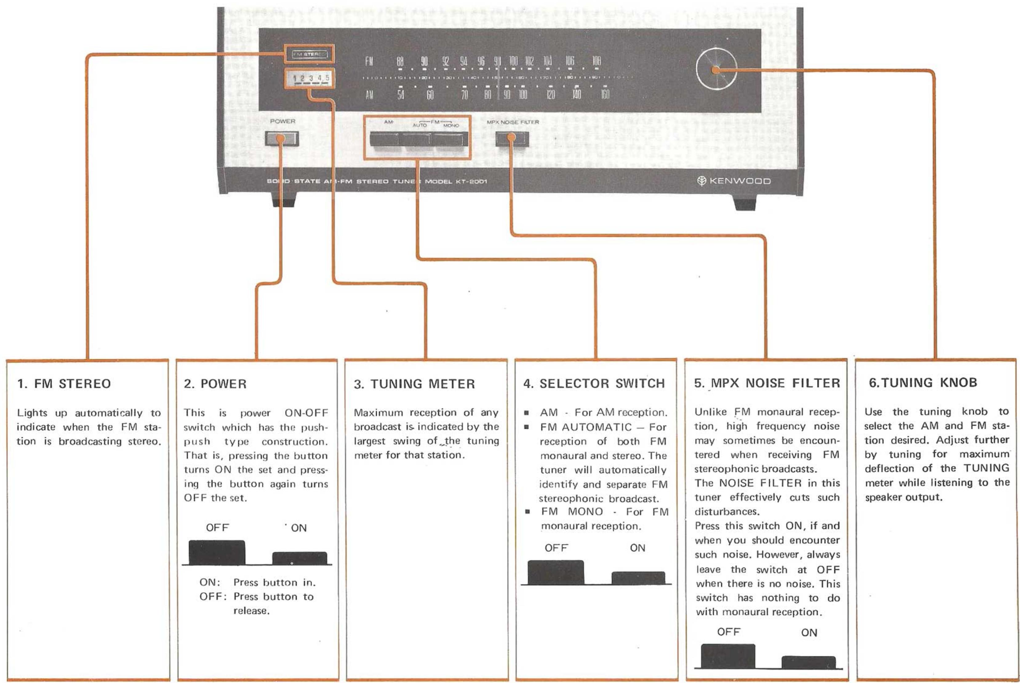
CONTROLS AND THEIR FUNCTIONS 7
OPERATINGINSTRUCTIONS 8
TROUBLESHOOTING 9
SPECIFICATIONS 10
MOUNTING TEMPLATE 11
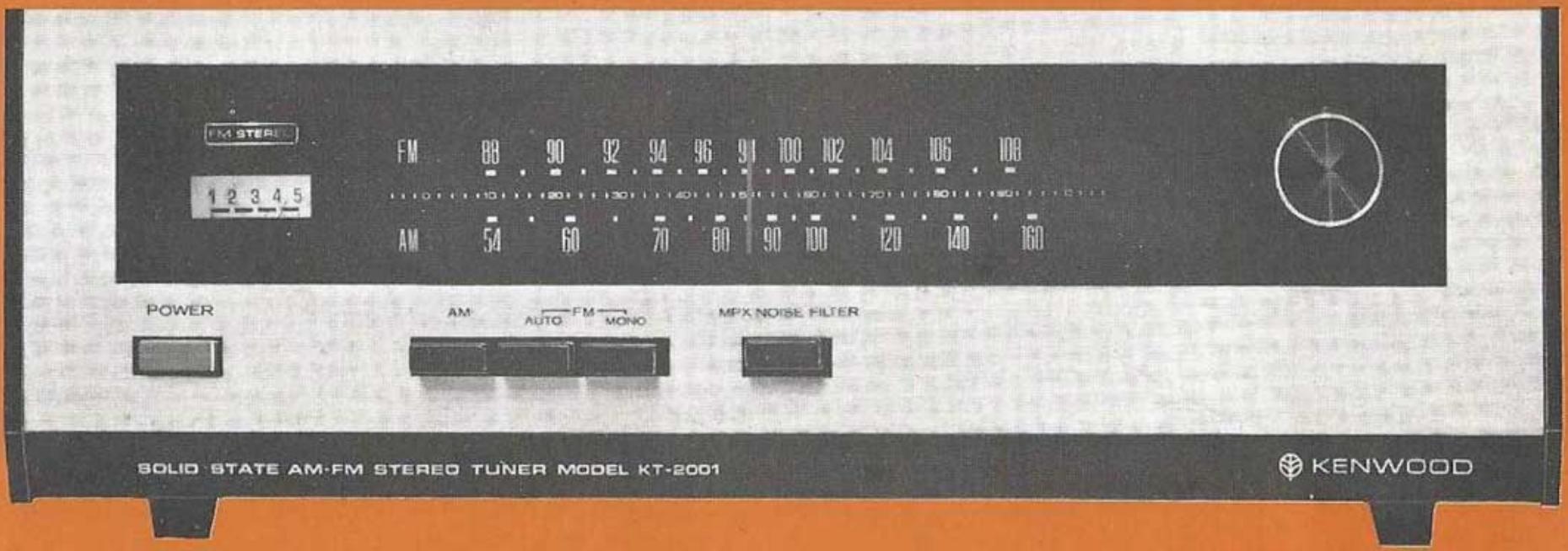
- FET's Front-end for Superior Sensitivity.
- Push-button controls regulate AM-FM AUTO-FM MONO Selector Switch and MPX Noise Filter.
- Automatic FM Stereo/Mono Silent Switching circuit with FM Stereo Indicator.
- MPX Noise Filter for eliminating noise on Stereo Signals without affecting the frequency response.
- 300 ohms balanced and 75 ohms unbalanced FM Antenna terminals.
- New Luminous Dial glass.
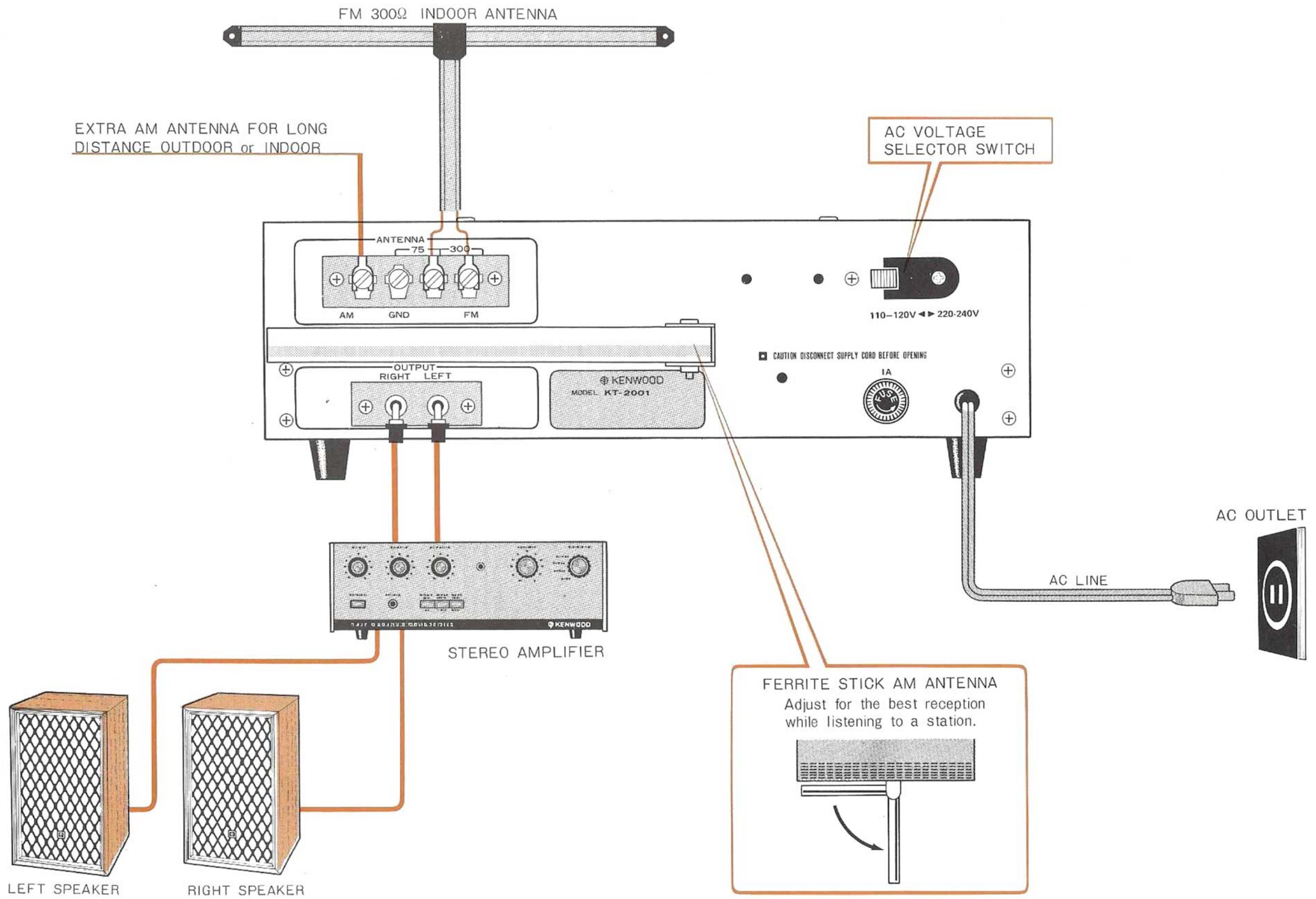
INTERCONNECTING DIAGRAM
OUTPUT
Signal from the output jacks are fed to the amplifier. Connecting cables should be plugged to the amplifier component's AUXILIARY or TUNER jacks. Shielded cables terminated at both ends with RCA type phono plugs which are supplied with this tuner.
If in your particular installation longer connecting cables are necessary, they may be used without fear of excessive high frequency losses as your KT-2001 has a low impedance. However, it is preferable to keep the length of these connecting cables within three or four yards whenever possible.
AM ANTENNA
The ferrite loop stick built into the Model KT-2001 assures adequate reception of all local AM stations. However, in fringe areas, high noise areas, or where surrounding metal objects interfere with normal reception, a regular antenna lead should be connected to the terminal designated AM.
NOTE: The ferrite loop stick is mounted on a swivel bracket. For maximum pickup, the loop stick should be swung away from the chassis.
FM ANTENNA
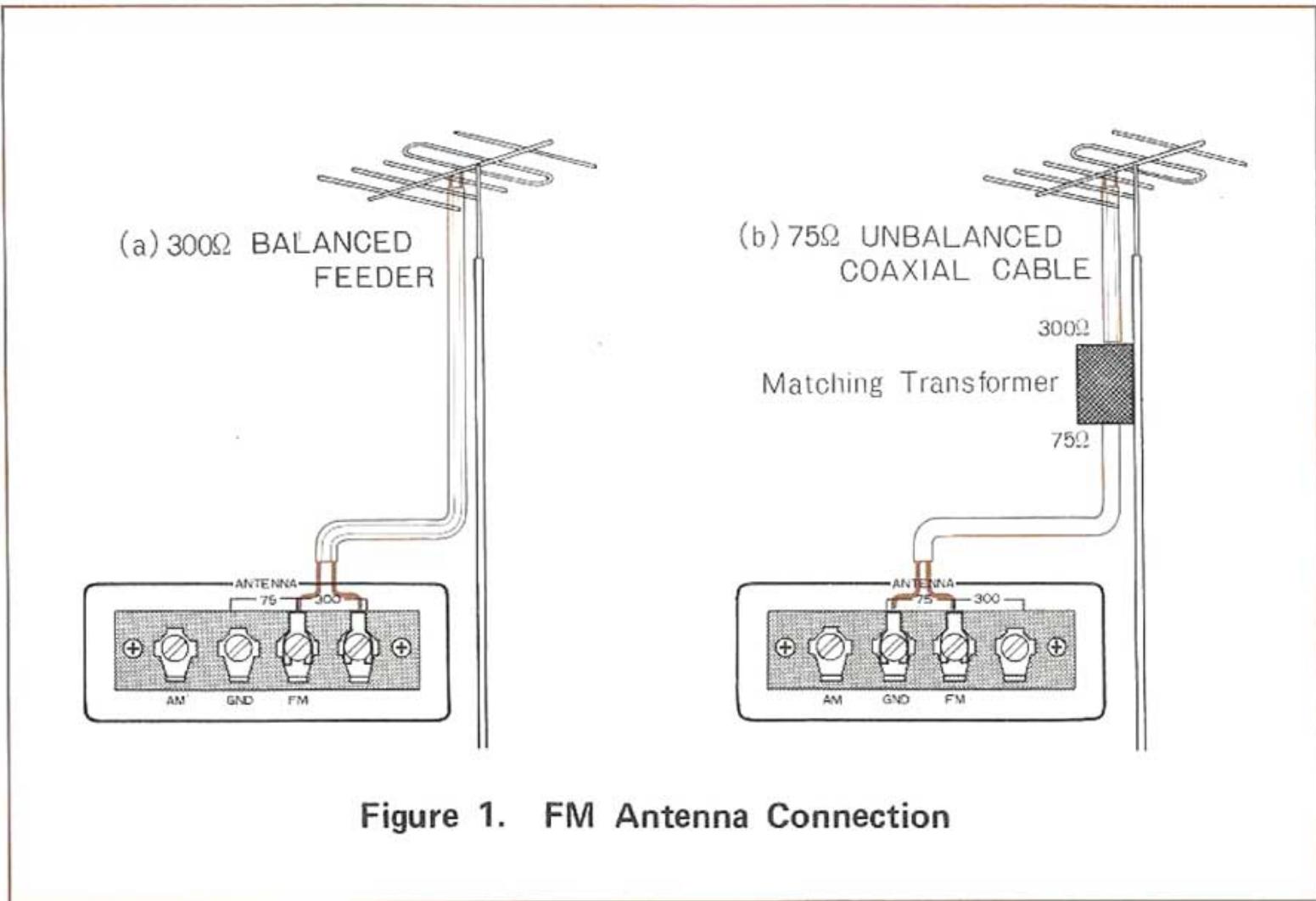
Three terminals are provided for connection to a 300 ohms and 75 ohms FM antenna as shown in Figure 1.
For good FM stereo reception, always use the best antenna possible. In areas close to the transmitter, a simple indoor dipole antenna may suffice. It should be remembered, however, that the pickup of reflections (similar to "ghosts" on TV) will result in poor stereo reception. These reflections must therefore be reduced to a minimum, either by careful orientation of the indoor antenna or, if this will not eliminate them, by using a more directional outdoor type antenna.
In areas a greater distance from the transmitter, the use of an outdoor antenna is highly recommended. These are available in various types. For reception of stations scattered in many directions, a non-directional type may be required. If the desired stations lie mostly in one direction, a high-directional type of antenna will offer better results. When using a directional antenna, always orient it for the best reception of the desired station. The correct position will be indicated by maximum deflection of the tuning meter on your tuner.
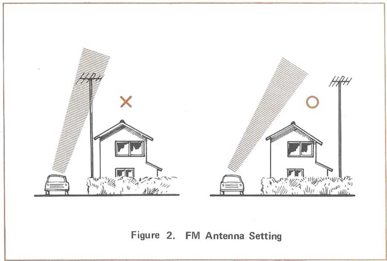
Do not place the FM antenna in the vicinity of a road (See Figure 2).
ELECTRICAL CONNECTIONS
POWER
Plug the AC line cord into an outlet furnishing 110 to 120 volts AC, 50 / 60Hz . The AC convenience socket of any accompanying amplifier unit may also be used for source of power (See Figure 3).
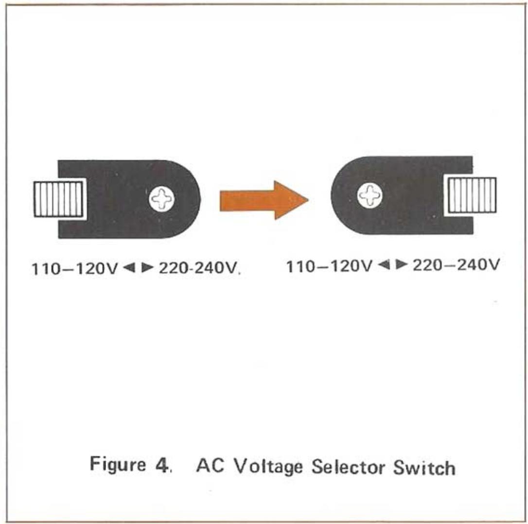
AC VOLTAGE SELECTION
This unit is pre-set to be used at 110-120 volts AC. In countries with 220-240 volts AC, set the AC Voltage Selector switch from 110-120 volts to 220-240 volts as follows:
- Turn the power switch to "OFF".
- Remove the black plate which is affixed to the AC Voltage Selector switch on the rear panel.
- Set the slide switch to the right.
- Attach the black plate to opposite side screw.
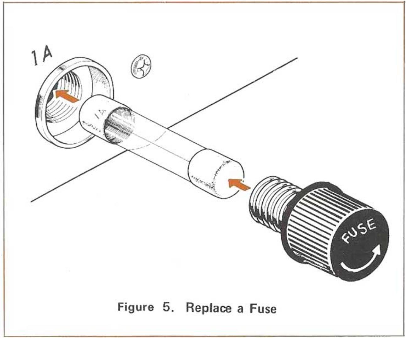
FUSE
A shield 1A fuse is used. Rotate the fuse holder counterclockwise for replacing. When the fuse has blown out, check carefully the reason for the blow-out and then replace the fuse. When something is wrong with the supply circuit, the fuse will blow again. Do not, in any case, use copper wire in place of the specified shield fuse.

Figure 4 illustrates the AC Voltage Selector swith set for 220-240 volts AC.
OPERATING INSTRUCTIONS
| CONTROL
OPERATION | POWER
SWITCH | SELECTOR
SWITCH | MPX NOISE
FILTER SWITCH | TUNING | TUNING
METER | FM STEREO
INDICATOR |
| FM
AUTO | STEREO | ON | FM AUTO | OFF
or
ON | Any desired
FM station | MAXIMUM
Deflection | Light up |
| MONO | ON | FM AUTO | OFF | Any desired
FM station | MAXIMUM
Deflection | - |
| FM MONO | ON | FM MONO | OFF | Any desired
FM station | MAXIMUM
Deflection | - |
| AM | ON | AM | OFF | Any desired
AM station | MAXIMUM
Deflection | - |
NOTES
MPX NOISE FILTER circuit blends a part of high frequency into sub channel and cuts noise without affecting the main channel and frequency response so that FM stereo broadcasting can be received clearly. It slightly reduces high frequency separation.
- When you cannot enjoy the reception of long distance FM stereo station due to noise interference, we recommend that you set the SELECTOR switch to FM MONO position and listen as monaural.
In initially installing this tuner, improper connections may result in one of the following indications of trouble. Their possible causes and corrective measures are listed below to facilitate installation.
INDICATIONS
| Occurs Only During AM Reception | Cause | Correction |
| Continuous low frequency buzz. Most noticeable at night on weak signal stations. | Interference from electrical appliances or atmospheres. | Erecting a 10 meter outdoor antenna and securing good ground conditions should reduce interference considerably. Complete elimination is difficult. |
| Continuous high frequency whine which incinerases at night. | TV interference.10 kHz beat interference from adjacent AM station. | Turn TV off. (Neighboring TV set may also be cause.) Impossible to eliminate from tuner side.This is one disadvantage of the AM broadcast system. |
| Intermittent buzzing or sharp crackling noise. | Lightning interference.Interference from fluorescent lamps. | Occurs when lamps are switching on and cannot be helped. |
| Tunable hum which occurs when broadcast is tuned in. | AC Plug Connection.Usually unavoidable in certain areas. | Try reversing AC plug connections.Occurs only on certain stations due to high voltage line or AC supply and cannot be helped. |
| Interference from amateur stations. | Called BCI, this interference results from neighboring amateur stations. (Also occurs on FM). | Consult interfering station operator or authorities concerned. |
| Occurs Only During FM Reception | Cause | Correction |
| Continuous hiss or buzzing interference with broadcast. Becomes louder during stereo. | Incoming signal too weak at ANT terminal. | Erect outdoor FM antenna if only indoor T-type is used.A 5 or 7 element antenna is necessary if you are located at a considerable distance from the broad-casting station. |
| Occasional sharp buzzing or crackling noise. | Automobile ignition noise. More noticeable on weak signals. | Erect outdoor FM antenna as far away from roads as practicable. |
| Weak right channel response when listening to LEFT SIDE test FM Stereo broadcast. | Called crosstalk, a very slight response is normal. | If leakage is less than one tenth, it is not a sign of trouble. It cannot be reduced to zero. |
| FM Automatic circuit fails to respond to stereo broadcast. | Incoming signal is exceptionally weak. | Erect a special FM outdoor antenna. |
FM SECTION
ANTENNA IMPEDANCE: 300 ohms balanced & 75 ohms unbalanced
USABLE SENSITIVITY: 2.0 v
HARMONIC DISTORTION: MONO; 0.5%
(at 400Hz 100% MOD) STEREO; 0.7%
SIGNAL TO NOISE RATIO: 60dB
CAPTURE RATIO (IHF): 4.0dB
SELECTIVITY (ALT. CH.) (IHF): 45dB
IMAGE REJECTION: 60dB
IF REJECTION: 100dB
AM SUPPRESSION: 45dB
STEREO SEPARATION (at 1kHz ): 30dB
(at 10kHz 20dB
SUB CARRIER SUPPRESSION: 40dB
STEREO AUTO-SWITCHING LEVEL: 10 V
FRONT END: 1-FET,3-Gang
IF STAGE: 1 IC
OUTPUT VOLTAGE: 1V
AM SECTION
ANTENNA: Built-in ferrite bar antenna & External antenna terminals
USABLE SENSITIVITY: 25 V
SIGNAL TO NOISE RATIO: 45dB
SELECTIVITY: 25dB
IMAGE REJECTION: 45dB
IF REJECTION: 35dB
FRONT END: 2-Gang
OUTPUT VOLTAGE: 0.4V
SELECTOR SWITCHES: AM, FM AUTO, FM MONO
SWITCH: MPX NOISE FILTER
SEMICONDUCTORS: 1-IC, 15-Tr., 26-Di.
POWER CONSUMPTION: 15 Watts
DIMENSIONS: 13^ (W)× 4 - 5 / 8^ (H)× 9 - 7 / 16^ (D)
WEIGHTS: 8.6 Lbs (3.9 Kg)
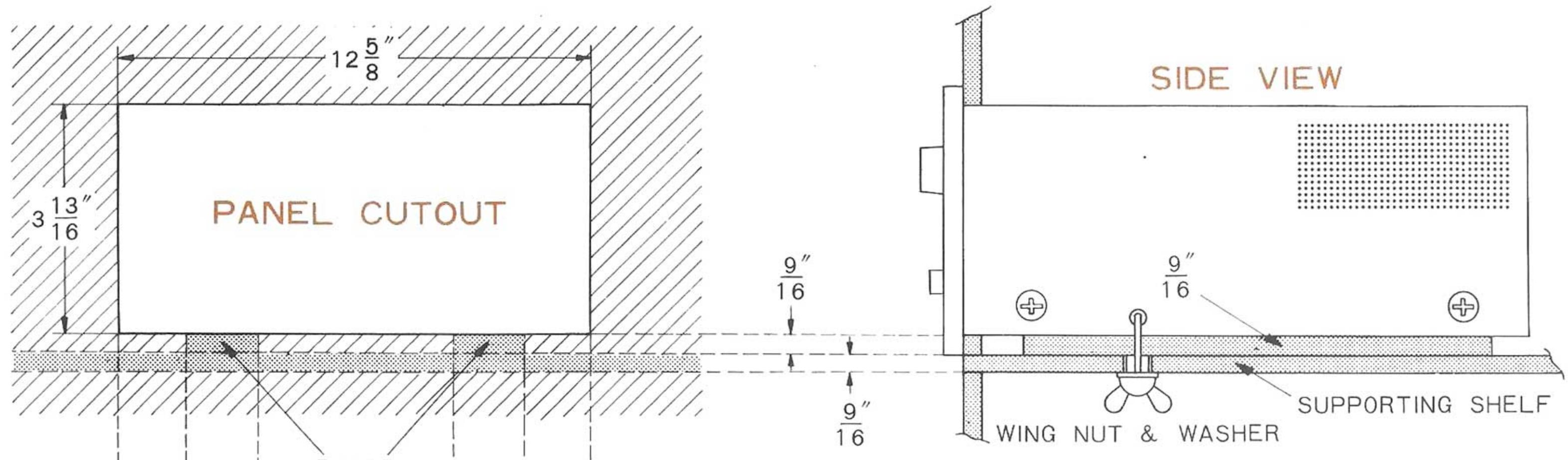
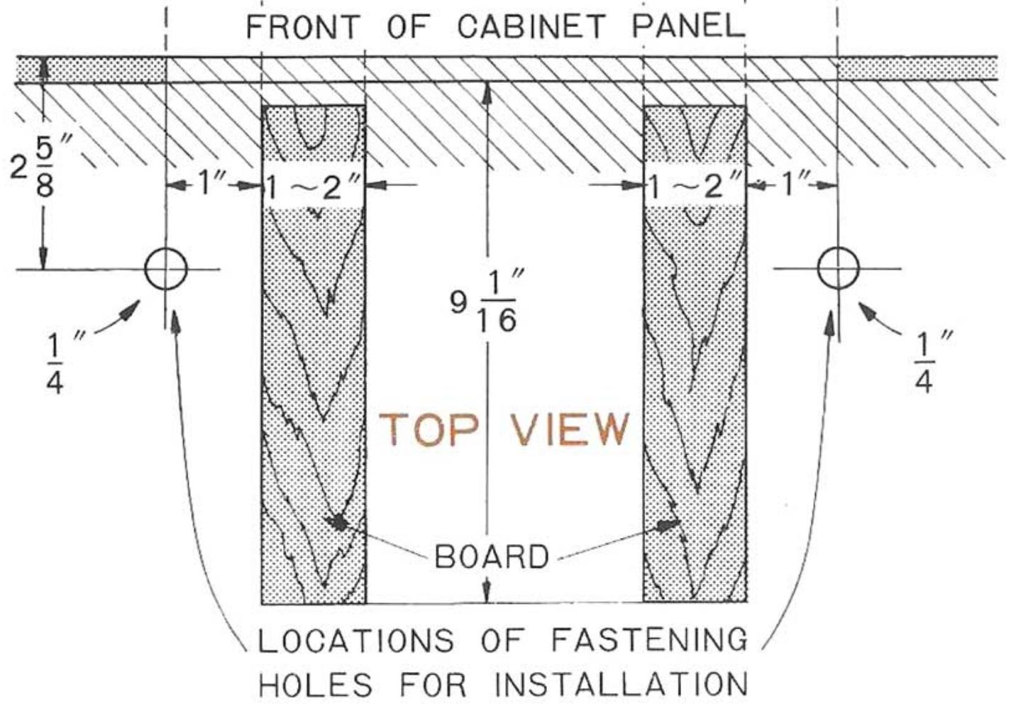
DIRECTIONS FOR PANEL MOUNTING
- Locate the supporting shelf at the height you wish the tunes positioned.
- Remove the four bottom legs.
- An air space must be made between the bottom of the set and the supporting shelf to assure good ventilation and cool operation. This space can be made by placing two boards which measure 9/16'' thick by 1'' to 2'' width between chassis and the supporting shelf.
- Using the full scale "Cutout Template" makes a 3-13/16" x 12-5/8" cutout in the cabinet panel. The bottom of the cutout should be flush with the bottom plate of the tuner, as shown in the side view. The distance between the bottom of the cutout and the top of the supporting shelf is 9/16".
- The tuner is held in place by two bolts. The holes must be made in the shelf to correspond with the holes in the tuner. Use the "Top View" template to locate these holes on the supporting shelf. The holes should be made 1/4'' in diameter or somewhat larger.

KENWOOD ELECTRONICS, INC.
15777 SOUTH BROADWAY, GARDENA, CALIFORNIA 90247
72-02 51st AVENUE, WOODSIDE, N.Y. 11377
CANADIAN EXCLUSIVE DISTRIBUTOR
MAGNASONIC CANADA LTD.
4980 BUCHAN ST. MONTREAL P.Q, CANADA
14 BANIGAN DRIVE THORNCLIFFE PARK TORONTO CANADA