
ST310L - Récepteur audio MARANTZ - Notice d'utilisation et mode d'emploi gratuit
Retrouvez gratuitement la notice de l'appareil ST310L MARANTZ au format PDF.

| Type de produit | Récepteur audio stéréophonique (tuner) |
| Marque | Marantz |
| Modèle | ST310L / ST430L |
| Bandes de réception | FM, AM (MW/LW) |
| Gamme de fréquences FM | 87,5 - 108 MHz |
| Gamme de fréquences AM (MW) | 522 - 1611 kHz |
| Gamme de fréquences AM (LW) | 153 - 360 kHz |
| Sensibilité FM mono | 0,7 µV (S/N 26 dB, 75 ohms) |
| Sensibilité FM stéréo | 25 µV (S/N 46 dB, 75 ohms) |
| Rapport signal/bruit FM mono | 76 dB (pondéré) |
| Rapport signal/bruit FM stéréo | 68 dB (pondéré) |
| Distorsion harmonique totale FM mono | 0,1 % |
| Distorsion harmonique totale FM stéréo | 0,2 % |
| Séparation stéréo FM | 45 dB |
| Nombre de préréglages | 16 (8 FM + 8 AM) |
| Affichage | Fréquence et mode (FM/AM, stéréo, indicateur de force du signal) |
| Dimensions (L x H x P) | 416 x 37 x 192 mm |
| Poids | 1,7 kg |
| Alimentation | 220-240 V CA, 50/60 Hz |
| Consommation électrique | Environ 10 W (estimation) |
| Connecteurs antenne FM | Bornes 300 ohms (antenne dipôle fournie) |
| Connecteurs antenne AM | Bornes AM et G (antenne cadre fournie) |
| Sorties audio | Prise jack (paire) pour amplificateur |
| Entretien | Confier à un technicien qualifié. Utiliser exclusivement des pièces d'origine. |
| Sécurité | Ne pas ouvrir. Risque de choc électrique. Débrancher avant entretien. |
| Accessoires inclus | Antenne FM dipôle, antenne AM cadre, cordon de sortie audio |
FOIRE AUX QUESTIONS - ST310L MARANTZ
Questions des utilisateurs sur ST310L MARANTZ
0 question sur cet appareil. Repondez a celles que vous connaissez ou posez la votre.
Poser une nouvelle question sur cet appareil
Téléchargez la notice de votre Récepteur audio au format PDF gratuitement ! Retrouvez votre notice ST310L - MARANTZ et reprennez votre appareil électronique en main. Sur cette page sont publiés tous les documents nécessaires à l'utilisation de votre appareil ST310L de la marque MARANTZ.
MODE D'EMPLOI ST310L MARANTZ
Model ST430/ST430L
OWNER'S MANUAL
STEREOPHONIC TUNER
MODEL ST430/ST430L TECHNICAL SPECIFICATIONS(DIN)
FM TUNER SECTION
Frequency Range 87.5 ~ 108 MHz
Usable Sensitivity Mono (S/N 26 dB, 75 ohms) 0.7 V Stereo (S/N 46 dB, 75 ohms) 25 V
Alternate Channel Selectivity 98 MHz 63 dB
Image Response Rejection 48 dB
IF Rejection 70 dB
Spurious Response Rejection 75 dB
AM Suppression 55 dB
Signal-to-Noise Ratio Unweighted Mono 70 dB Stereo 63 dB Weighted Mono 76 dB Stereo 68 dB
Pilot Signal & Subcarrier Rejection 19 kHz 35 dB 38 kHz 45 dB
Total Harmonic Distortion Mono 0.1% Stereo 0.2%
Frequency Response 30Hz 15kHz +0.5 dB, -1.5 dB
Separation Stereo 45 dB Channel Balance 0.2 dB
MW TUNER SECTION
Frequency Range 522\~1611 kHz
Usable Sensitivity 20 dB S/N 30% Mod., 999 kHz 500 V/m
Selectivity 999kHz, ± 9kHz 30 dB
Image Rejection, 999 kHz 40 dB
IF Rejection, 999 kHz 55 dB
Signal-to-Noise Ratio, 999 kHz 43 dB
Total Harmonic Distortion, 999 kHz 1.2%
LWTUNERSECTION
Frequency Range 153\~360 kHz
Usable Sensitivity 20 dB S/N 30% Mod., 250 kHz 800 μV
Image Rejection, 250 kHz 50 dB
IF Rejection, 250 kHz 50 dB
Signal-to-Noise Ratio, 250 kHz 43 dB
GENERAL
Power Requirements (ST430) 110-120/220-240 V AC, 50/60 Hz (ST430L) 220-240 V AC, 50/60 Hz
Dimensions Panel Width 416 mm Panel Height 37 mm Depth 192 mm
Weight Unit Alone 1.7 kg
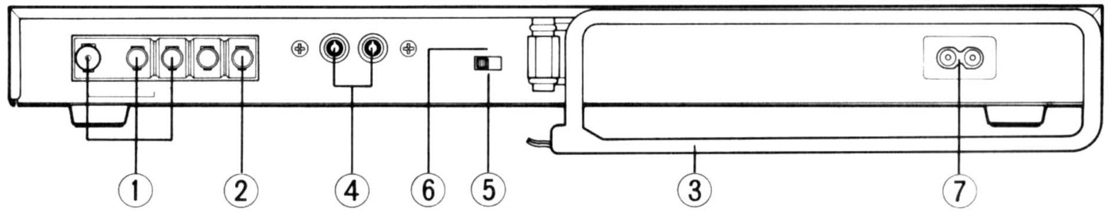
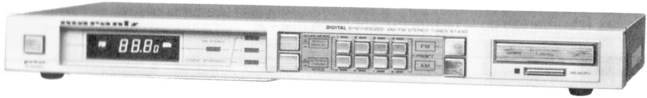
Model ST430
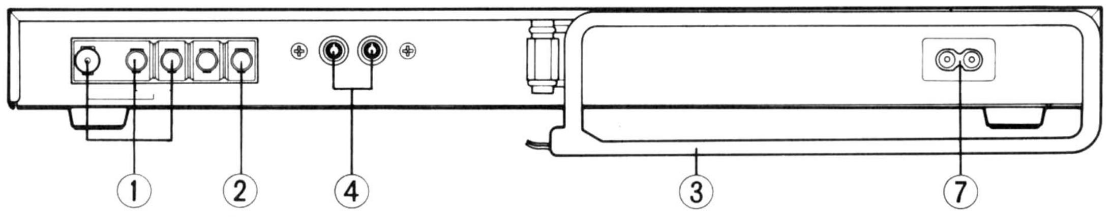
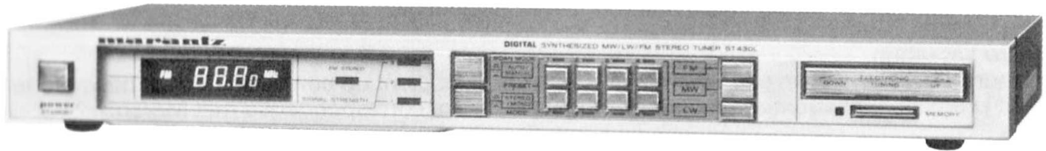
Model ST430L
Figure 1. Rear Panel
Figure 1. Panneau arrière
Abbildung 1. Geräterrückseite
Model ST430
Model ST430L
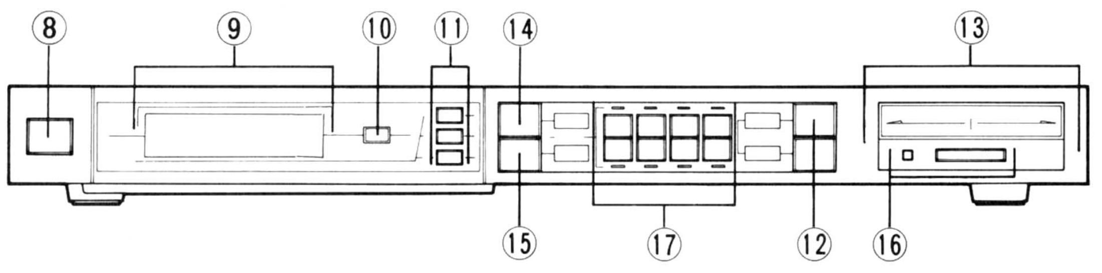
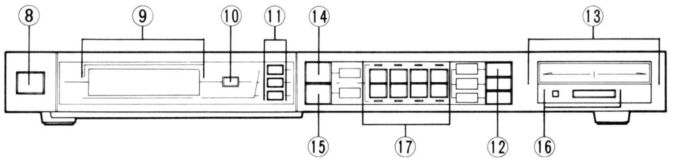
Figure 2. Front Panel
Figure 2. Face avant
Abbildung 2. Gerätevorderseite
FOREWORD
Your Marantz product has been specially prepared to comply with the household power and safety requirements that exist in your region. This product has a 2-position voltage selector (110-120/220-240V) on the bottom panel (A, N and T versions). Since the voltage has been adjusted as shown below upon shipment from the factory, please check the third alphabetical letter of the serial number and refer to the following table to note the characteristics of the model in your possession:
SUFFIX VOLTAGE
| A - | 240V AC, 50/60 Hz |
| C - | 120V AC, 60 Hz |
| U - | 120V AC, 60 Hz |
| N - | 220V AC, 50/60 Hz |
| T - | 240V AC, 50/60 Hz |
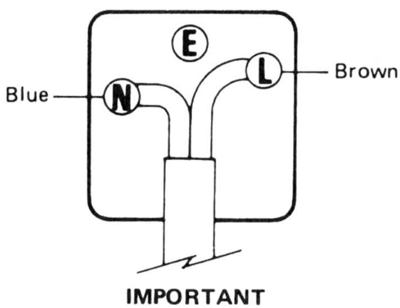
FOR UNITS SOLD IN THE UNITED KINGDOM
The wires in the mains lead are colored in accordance with the following code:
Blue Neutral
Brown -Live
As the colors of the wires may not correspond with the terminal identification in your plug, proceed as follows:
- Connect the brown wire to the terminal marked "N" or colored brown or red.
- Connect the blue wire to the terminal marked "L" or colored blue or black.
For 13A plug, conforming to BS1363, use a 3A fuse.
For other plugs, use a 5A or lower fuse in the plug or adaptor or at the distribution board.
ABOUT THIS MANUAL
Refer to the figures given on page 3. The callout numbers correspond to those found in this manual. All references to the connections and controls are printed in BOLD-FACE type as they appear on the unit.
REAR PANEL CONNECTIONS
All connections to the rear panel should be made with the power to the entire system turned off. To avoid confusion, connect one cable at a time between the different components of your system. This is the safest way to avoid cross-connecting channels or confusing signal inputs with outputs.
Since the loop antenna is not connected to the tuner, begin installation by installing the loop antenna. (See Figure 6)
1 FM ANTENNA
Included in the accessory kit is a ribbon-type "folded dipole" FM antenna which should be connected to the terminals marked "300Ω". This type of antenna is simple and practical and will give adequate results in primary signal areas. If you are located in a fringe signal area, an outdoor antenna will be necessary. Even if you live in a strong signal location, an outdoor directional antenna will give you better results.
We do not recommend using master antenna systems, such as those found in apartment buildings. Such systems are usually designed expressly for television reception and frequently suppress or reduce the quality of the FM signals before distribution.
Where outdoor antennas are prohibited or inconvenient, the simplest from of "rabbitear" TV antenna is the most practical and will give satisfactory results. This type is preferred over the folded dipole because it can be more readily rotated for the best reception.
OUTDOOR AM ANTENNA
Two single wires are required to make an AM outdoor antenna. First, connect one single wire to the AM ANTENNA terminal on the rear panel, and the other end to a very high horizontal antenna wire of 7 to 20 meters in length suspended between insulators in an outdoor location (the higher the better). Next, connect the second single wire between the G terminal of your tuner and an authenticated earth ground.
③ AM LOOP ANTENNA
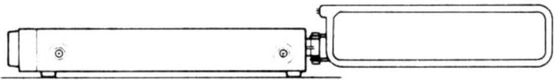
Your tuner is equipped with a high performance, noise-free AM LOOP ANTENNA held on the rear panel with a snap-in hinge. Swivel it out for best AM (MW, LW) reception as shown in figure 4. For improved AM (MW, LW) reception remove the antenna from the hinge and hang it on a nearby wall. The length of the antenna cord is 60~cm and it should not be pulled tight.
- For Model ST430L
AM LOOP ANTENNA CONNECTION
Securely connect the loop antenna leads to the AM and G terminals of the "ANTENNA TERMINAL" of the unit as shown in Fig. 4.
(4) OUTPUT JACKS
Connect the output jacks to the Tuner inputs of your amplifier with the cord supplied.
5 SCAN STEP SELECTOR
Changes the step when the tuner searches for the next station up and down the scale. In Europe this switch should be set for 50 kHz steps in FM and 9 kHz steps in AM.
CAUTION
THE UNIT MUST BE TURNED OFF BEFORE CHANGING THE SCAN STEP SELECTOR SWITCH POSITION.
6 FM DE-EMPHASIS SWITCH
A, N and T version models are equipped with switchable de-emphasis. In synthesizer models the switch works together with scan step switch.
The de-emphasis is set on 50~ s when delivered from the factory. The tuner can also be used in areas of 75~ s . In these areas, you must also set the scan step switch to FM 100 kHz and AM to 10 kHz.
7 AC POWER CONNECTION
The correct voltage for operating your.
tuner is written on the rear panel. Besure the POWER push-switch is out before plugging the AC line cord into an electrical outlet.
The voltage selector is installed on bottom side of the unit.
The AC mains-switch is secondary connected and doesn't disconnect the unit from the AC mains in "OFF" position.
FRONT PANEL FEATURES
8 POWER/STANDBY SWITCH
When depressed supplies AC power to the unit.
9 FREQUENCY/MODE INDICATOR
The frequency received is indicated on the FREQUENCY DISPLAY. The tuner mode is also indicated as follows:
AM or FM: Indicates the band being received.
MHz or kHz: Indicates the unit of the frequency received: MHz for FM and kHz for AM (MW, LW*).
- For Model ST430L
10 FM STEREO
Lights up when a stereo broadcast is received.
11 SIGNAL STRENGTH
Indicates the strength of the incoming signal: the greater the number of LED's lit, the stronger the signal.
12 BAND SELECTOR
Press the corresponding key to select FM or AM (MW, LW).
For Model ST430L
13 ELECTRONIC TUNING SWITCHES
When the UP or DOWN switch is depressed with the SCAN MODE switch set to MANUAL the frequency is scanned up or down in single steps in accordance with the position of the SCAN STEP SELECTION switch. When the UP or DOWN key is pressed for more than 0.5 sec and the SCAN MODE switch is set to AUTO the frequency is scanned up or down continuously.
14 SCAN MODE
When in the OUT position automatic scanning is performed.
When in the IN position manual scanning is performed.
15 MODE SWITCH
When it is set to the OUT position the MODE is put into STEREO.
When it is set to the IN position the MODE is put into MONO.
When the STEREO indicator triggers intermittently press this switch to convert the signal to the MONO mode.
(16) MEMORY SWITCH
Tune to the desired station, press the MEMORY switch and while the MEMORY light is on (10 sec.) press one of the 8 PRESET buttons.
17 PRESET BUTTONS 1-8
When one of these buttons is pressed the corresponding LED located above the buttons lights and the frequency stored in the corresponding memory is recalled in the mode determined by the position of the BAND selector. It is thus possible to memorize 8 stations each in FM and AM (MW'LW*).
- For Model ST430L
TUNING PROCEDURES
The stereo tuner does not have a conventional tuning dial or tuning knob. There are two tuning methods: Preset tuning and Ordinary tuning.
PRESET TUNING
A total of 16 stations [8AM (MW, LW*) and 8 FM] can be preset. Refer to MEMORY SWITCH on page 6. Turning the tuner On and Off will not cause the tuner to "forget" the stations programmed. Built-in storage capacitors will supply power to the memory circuits for about one week if the unit is unplugged.
- For Model ST430L
ORDINARY TUNING
Refer to ELECTRONIC TUNING SWITCHES page 6.
DESCRIPTION
Set the position of the tuner's loop antenna to obtain the best reception. (See Figure 5)
It is also possible to remove the loop antenna and install it in a separate location. (See Figure 7)
MAINTENANCE
Only the most competent and qualified technicians should be allowed to service your system. The Marantz company and its factory trained technicians have the knowledge and special equipment needed for repair and calibration of this precision instrument.
In the event of difficulty refer to your dealer or write directly to one of the locations listed at the end of this manual for the name and address of the Marantz service station nearest your home. Please include the model and serial number of your unit together with a description of what you feel is abnormal in its behaviour.
REPACKING FOR SHIPMENT
Should it become necessary to repack your Stereo Cassette Deck for shipment to the factory, to an authorized service station, or elsewhere, please observe the following precautions:
a. Pack the unit carefully, using the original material as shown in Figure 8
b. Ship via a reputable carrier (do not use Parcel Post) and obtain a shipping receipt from the carrier.
c. Be sure to include your return address on the shipping label.
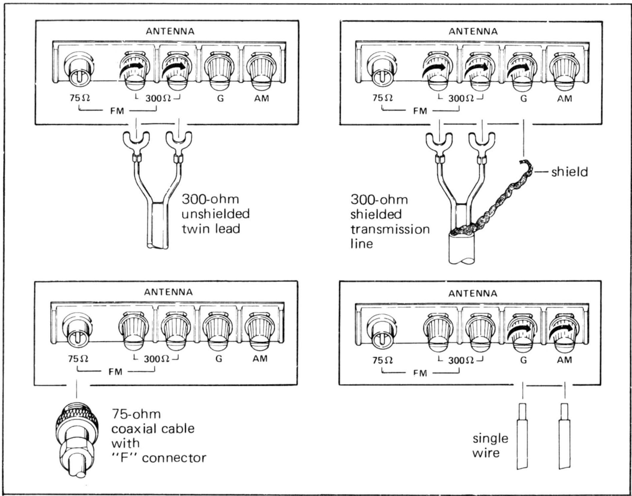
Figure 3.
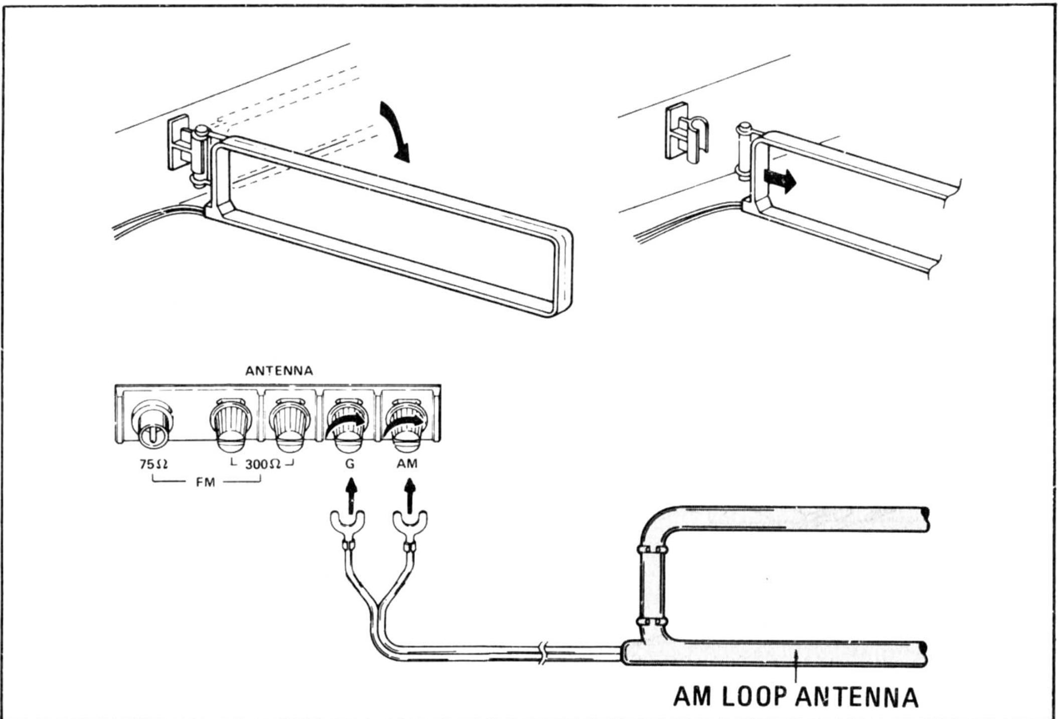
Figure 4.
Tuner
Tuner
Amplifier
Cassette Deck
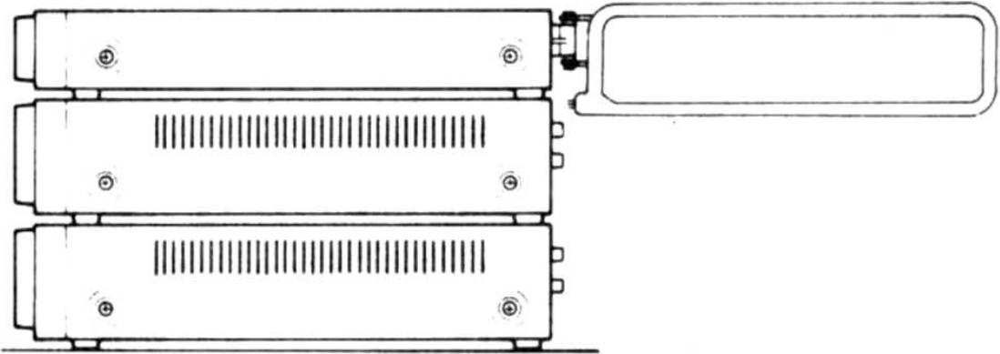
Figure 5.
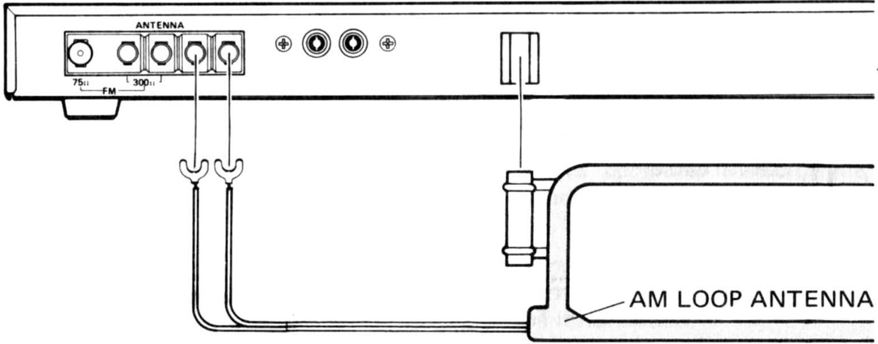
Figure 6.
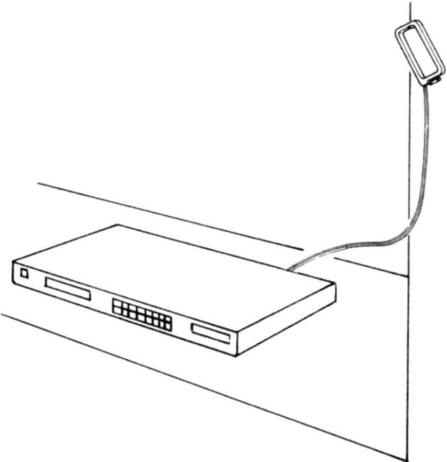
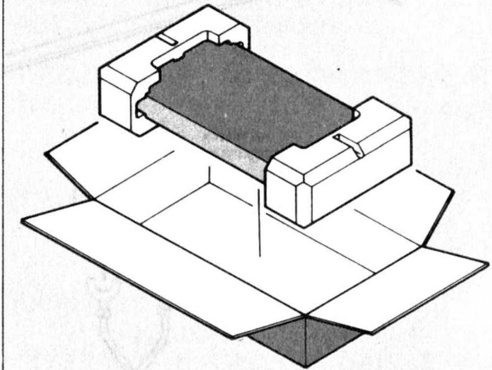
Figure 7.
Figure 8.
VOTE ON SAFETY :
symbol Fire or electrical shock hazard. Only original parts
should be used to replace any part marked with symbol .
Any other component substitution (other than original
ype), may increase risk of fire or electrical shock hazard.
- Model ST430/ST430L
- OWNER'S MANUAL
- STEREOPHONIC TUNER
- MODEL ST430/ST430L TECHNICAL SPECIFICATIONS(DIN)
- FM TUNER SECTION
- MW TUNER SECTION
- LWTUNERSECTION
- GENERAL
- FOREWORD
- ABOUT THIS MANUAL
- REAR PANEL CONNECTIONS
- FM ANTENNA
- OUTDOOR AM ANTENNA
- ③ AM LOOP ANTENNA
- AM LOOP ANTENNA CONNECTION
- OUTPUT JACKS
- SCAN STEP SELECTOR
- CAUTION
- FM DE-EMPHASIS SWITCH
- AC POWER CONNECTION
- FRONT PANEL FEATURES
- POWER/STANDBY SWITCH
- FREQUENCY/MODE INDICATOR
- FM STEREO
- SIGNAL STRENGTH
- BAND SELECTOR
- ELECTRONIC TUNING SWITCHES
- SCAN MODE
- MODE SWITCH
- MEMORY SWITCH
- PRESET BUTTONS 1-8
- TUNING PROCEDURES
- PRESET TUNING
- ORDINARY TUNING
- DESCRIPTION
- MAINTENANCE
- REPACKING FOR SHIPMENT
Marque : MARANTZ
Modèle : ST310L
Catégorie : Récepteur audio