
CD 73 - Lecteur CD MARANTZ - Notice d'utilisation et mode d'emploi gratuit
Retrouvez gratuitement la notice de l'appareil CD 73 MARANTZ au format PDF.

| Type de produit | Lecteur CD compact |
| Marque | Marantz |
| Modèle | CD 73 |
| Dimensions (fermé) | 416 x 81 x 300 mm |
| Dimensions (ouvert) | 416 x 130 x 483 mm |
| Poids | 8 kg environ |
| Alimentation | 40 W, 110-120/220-240 V AC, 50/60 Hz |
| Plage de fréquences | 20 - 20 000 Hz |
| Rapport signal/bruit | > 90 dB |
| Distorsion harmonique totale | < 0,005 % |
| Conversion numérique/analogique | 16 bits avec filtre numérique |
| Système de correction d'erreurs | Cross Interleave Reed Solomon (CIRC) |
| Laser | Semi-conducteur AlGaAs, longueur d'onde 0,78 μm |
| Vitesse de rotation du disque | 500 - 200 tr/min (de l'intérieur vers l'extérieur) |
| Durée de lecture maximale | 60 minutes (stéréo) |
| Format de disque | CD (120 mm de diamètre) |
| Niveau de sortie audio | 2 V rms |
| Fonctions de lecture | Lecture, pause, arrêt, avance/retour rapide, répétition, programmation |
| Télécommande | Système bus Marantz (télécommande optionnelle) |
| Convertisseur de tension | Sélecteur de tension sur le panneau arrière (110/120/220/240 V) |
| Entretien | Nettoyer avec un chiffon doux et sec. Ne pas utiliser de solvants. |
| Sécurité | Débrancher le cordon d'alimentation avant toute manipulation interne. |
| Pièces détachées | Références détaillées dans le manuel de service |
FOIRE AUX QUESTIONS - CD 73 MARANTZ
Questions des utilisateurs sur CD 73 MARANTZ
0 question sur cet appareil. Repondez a celles que vous connaissez ou posez la votre.
Poser une nouvelle question sur cet appareil
Téléchargez la notice de votre Lecteur CD au format PDF gratuitement ! Retrouvez votre notice CD 73 - MARANTZ et reprennez votre appareil électronique en main. Sur cette page sont publiés tous les documents nécessaires à l'utilisation de votre appareil CD 73 de la marque MARANTZ.
MODE D'EMPLOI CD 73 MARANTZ
HiFi ENGINE
For more Hi-Fi manuals and set-up information
please visit www.hifiengine.com
SERVICE MANUAL
CD-73

manantz
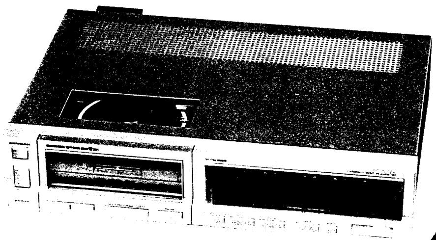
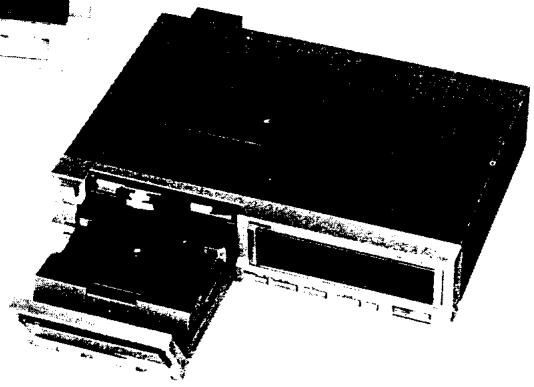
model CD-73
Compact Disc Player
TABLE OF CONTENTS
SECTION
PAGE
- INTRODUCTION 1
- P.W. BOARDS 1
- DRAWER MOTOR CONTROL P.W. BORAD WORKING PRINCIPLE 2
- ADJUSTMENT PROCEDURES FOR DISC CLAMPER 3
- VOLTAGE CONVERSION 4
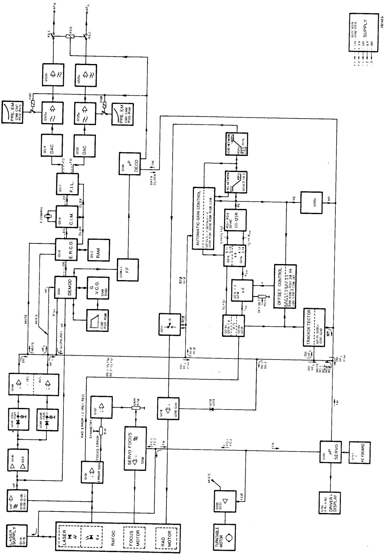
- SIGNAL BLOCK DIAGRAM 5
- COMPONENT LOCATIONS (AND WIRE CONNECTIONS) 6
- DIAGRAM AND COMPONENT LOCATIONS 8
8.1 Servo (P200) Schematic Diagram and Component Locations 8
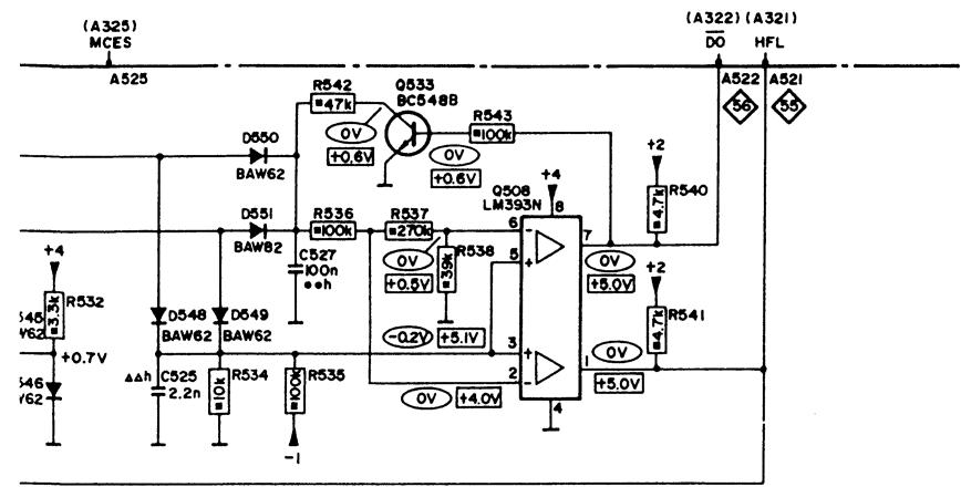
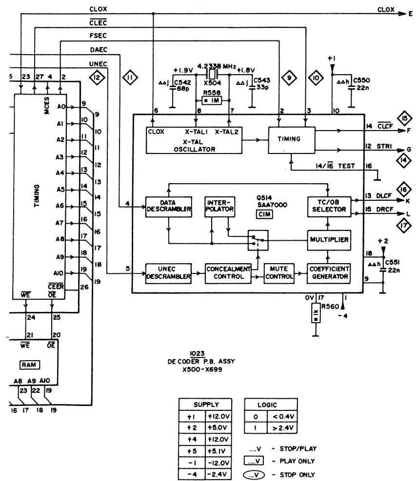
8.2 Decoder (P500) Schematic Diagram and Component Locations 13
8.3 Power Supply (P100) Schematic Diagram and Component Locations 18
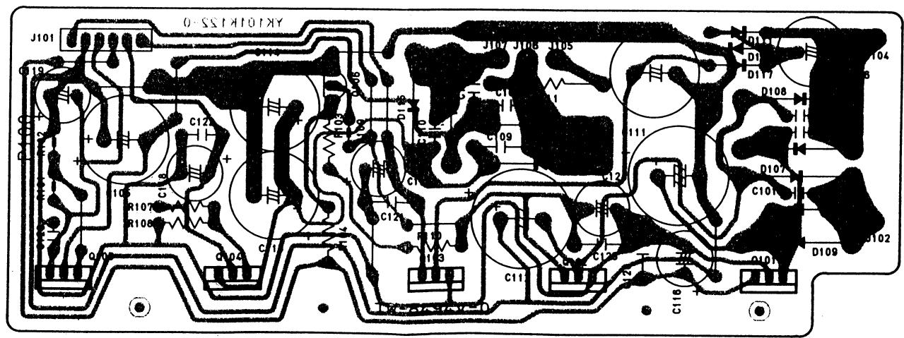
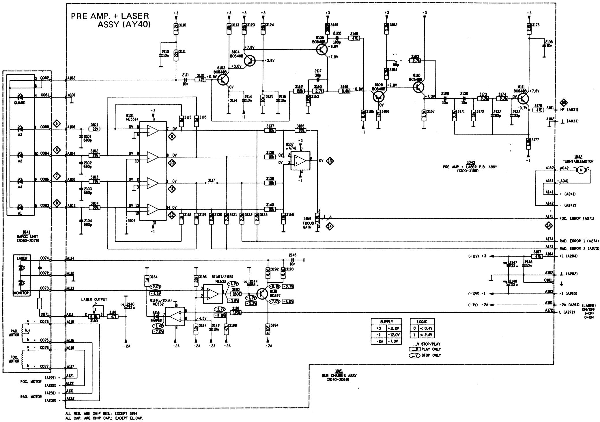
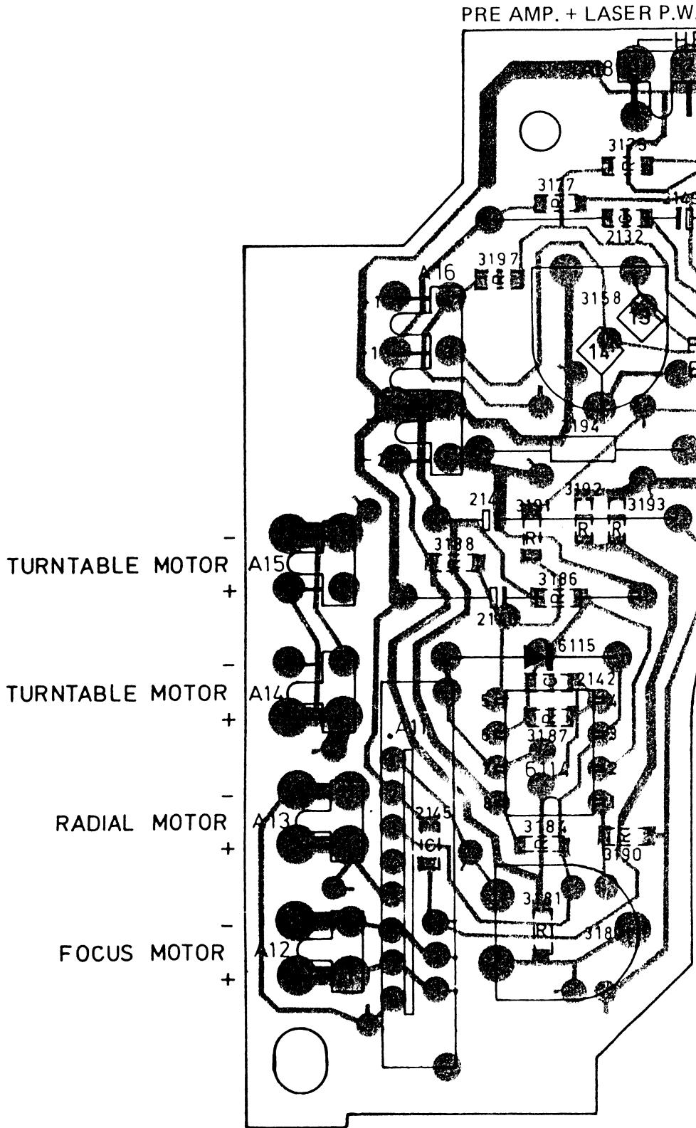
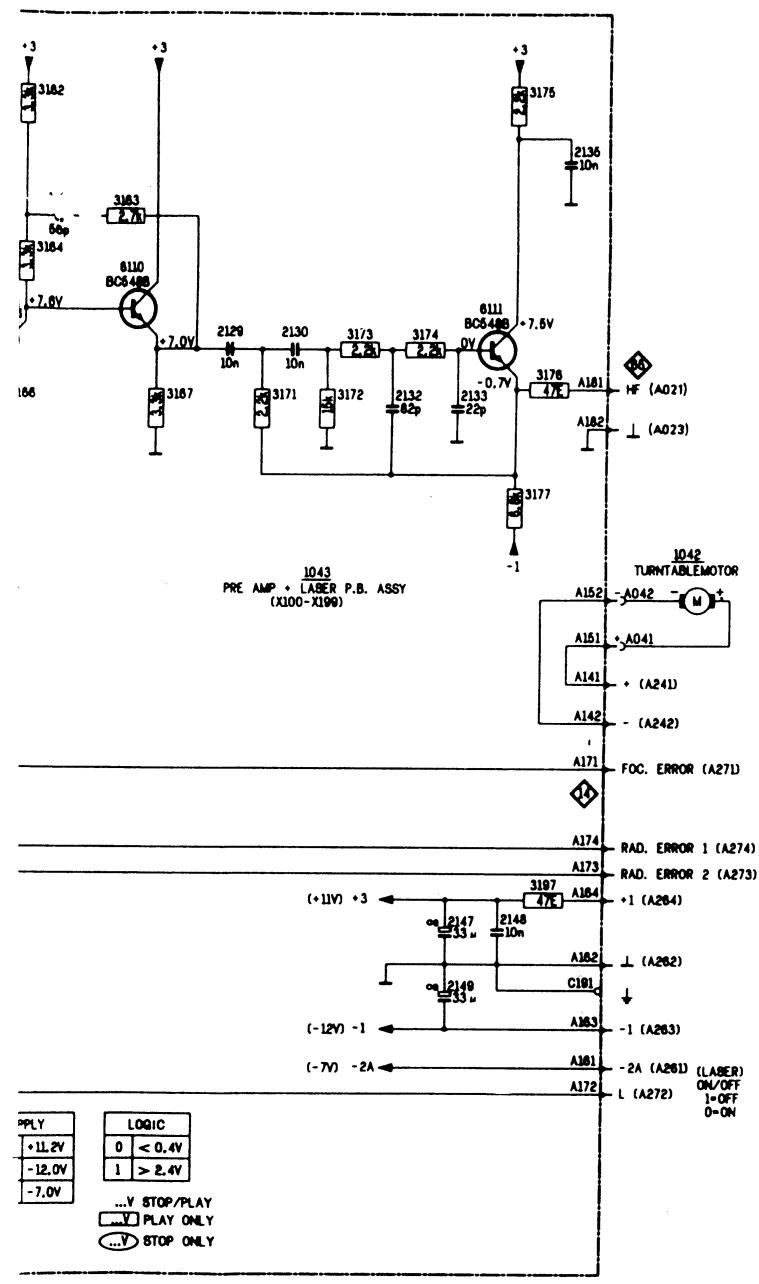
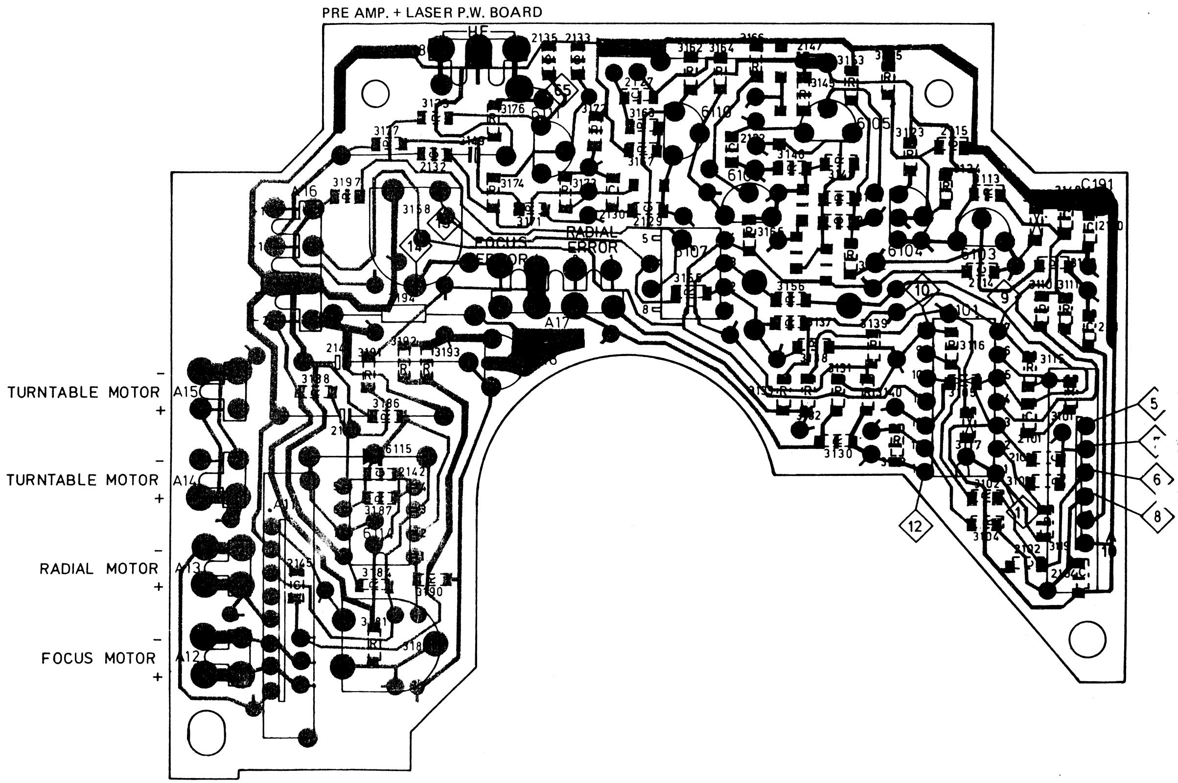
8.4 Pre Amp. + Laser (AY40) Schematic Diagram and Component Locations 19
-
EXPLODED VIEW AND PARTS LIST 22
-
ELECTRICAL PARTS LIST 30
- TECHNICAL SPECIFICATIONS 38
- SCHEMATIC DIAGRAM 40
1. INTRODUCTION
This service manual was prepared for use by Authorized Warranty Stations and contains service information for Marantz Model CD-73 Compact Disc Player.
Servicing information and voltage data included in this manual are intended for use by the knowledgeable and experienced technician only. All instructions should be read carefully. No attempt should be made to proceed without a good understanding of the operation of the Compact Disc Player.
The parts list furnishes information by which replacement parts may be ordered from the Marantz Company. A simple description is included for parts which can usually be obtained through local suppliers.
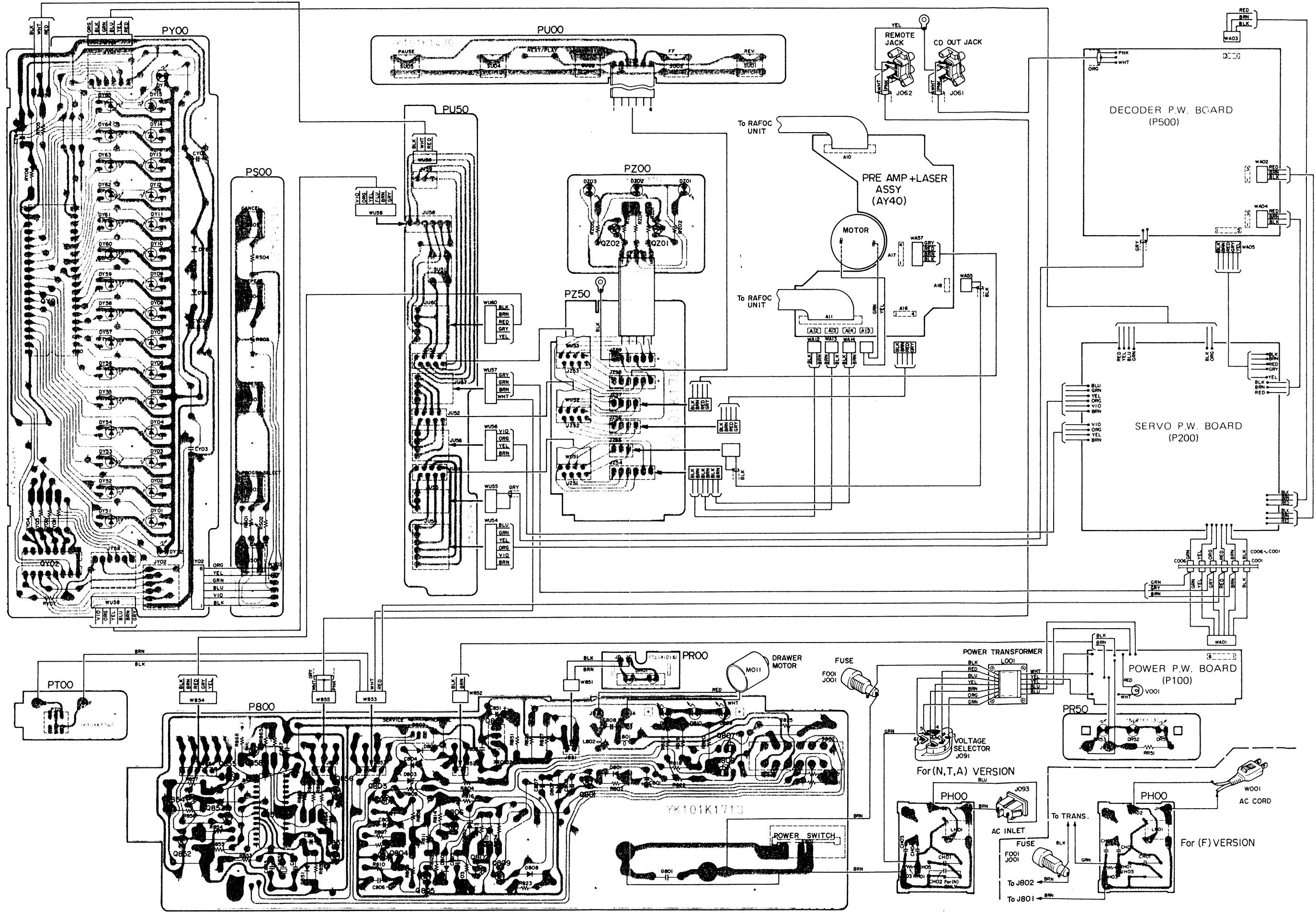
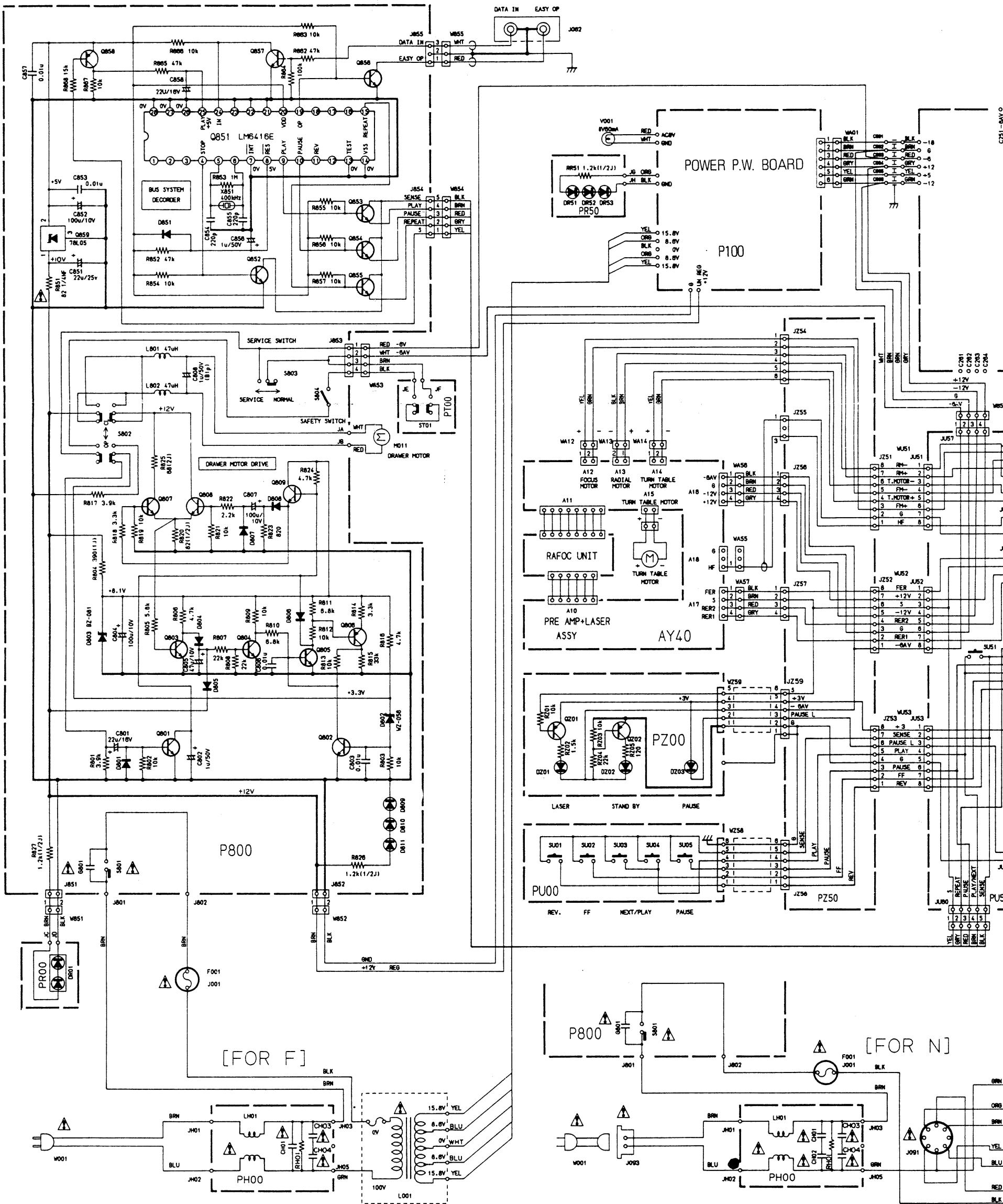
2. P.W. BOARDS
- Power Supply . . . . . . . . . . . . . . . . . . . . . . . . . . . . . . . . . . . . . . . . . . . . . . . . . . . . . . . . . . . . . . . . . . . . . . . . . . . . . . . . . . . . . . . . .
- P.W. Board P100
- Servo . . . . . . . . . . . . . . . . . . . . . . . . . . . . . . . . . . . . . . . . . . . . . . . . . . . . . . . . . . . . . . . . . . . . . . . . . . . . . . . . . . . . . .. mounted on P.W. Board P200
- Decoder . . . . . . . . . . . . . . . . . . . . . . . . . . . . . . . . . . . . . . . . . . . . . . . . . . . . . . . . . . . . . . . . . . . . . . . . . . . . . . . . . . . . . . . . . . . . . P500
- Motor/Remocon......mounted on P.W. Board P800
- Main Filter . . . . . . . . . . . . . . . . . . . . . . . . . . . . . . . . . . . . . . . . . . . . . . . . . . . . . . . . . . . . . . . . . . . . . . . . . . . . . . . . . . . . . . . . . . . . . . . . P.W. Board PH00
- Power Indicator . . . . . . mounted on P.W. Board PR00
- Disc Inside Indicator . .mounted on P.W. Board PR50
- Program Key Switch.. .mounted on P.W. Board PS00
- Mode Key Switch . . . . . . mounted on P.W. Board PU00
- Signal Relay 2 . . . . . . . . . . . . . . . . . . . . . . . . . . . . . . . . . . . . . . . . . . . . . . . . . . . . . . . . . . . . . . . . . . . . . . . . . . . . . . . . . . . . . P.W. Board PU50
- Display . . . . . . . . . . . . . . . . . . . . . . . . . . . . . . . . . . . . . . . . . . . . . . . . . . . . . . . . . . . . . . . . . . . . . . . . . . . . . . . . . . . . . . . . . . . . . . P.W. Board PY00
- Mode Indicator . . . . . . . . . . . . . . . . . . . . . . . . . . . . . . . . . . . . . . . . . . . . . . . . . . . . . . . . . . . . . . . . . . . . . . . . . . . . . . . . . . . . . . P.W. Board PZ00
- Signal Relay 1 . . . . . . . mounted on P.W. Board PZ50
- Pre Amp. + Laser . . . . mounted on P.W. Board AY40
3. DRAWER MOTOR CONTROL P.W. BORAD WORKING PRINCIPLE
Drawer motor control P. W. Borad includes the following.
(1) Drawermotor drive circuit
(2) Remote control circuit (Marantz Bus System decoder circuit)
3.1Drawer Motor Drive Circuit
A. Outline of the system
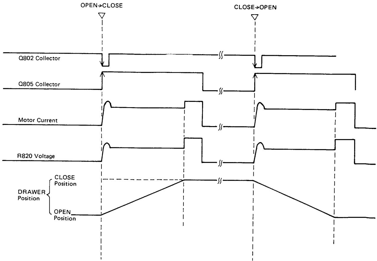
This circuit revolves and reverses the drawer motor by the OPEN/CLOSE switch of S802 on the front panel to open and close the drawer. It includes a circuit to increase starting torque and a safety circuit which stops automatically when something is caught in the drawer.
B. Operation of each part
a) Q809, Q808 and Q807 are motor drive circuits. Especially Q808 increases motor starting torque.
b) When the voltage of R820 becomes over about 0.6V , the base current begins to flow through Q803. That is, the motor is locked to detect the excessive current.
c) Q805 and Q806 make up a set/reset flip flop, which is set whell positive voltage is put into the base of Q805. And it is reset when the base becomes 0. As long as it is set, D806 is "ON" and motor drive circuit does not operate.
d) Q802 becomes "ON" just for a few msec when the OPEN/CLOSE switch of S802 is pushed. (S802 is non-shorting type.)
e) Q801 becomes "ON" just for the time-constant t1 based on R816/R801/C801only afterS802 is changed from CLOSE to OPEN, and makes the base of Q809 0V to stop the motor drive circuit.
Meanwhile, the voltage of C807 is discharged to increase the torque for the time-constant t_2 of C807/ R822 just after the end of t_1 .
C. Explanation of overall operation
a) During the shift of OPEN/CLOSE switch S802, from OPEN to CLOSE, Q802 becomes "ON" in an instant and flip flop which is composed of Q805 and Q806 is reset to cut off D806.
b) Consequently motor drive circuit which is composed of Q809, Q808 and Q807 begins to operate to switch on the drawer motor.
c) When the drawer comes to the mechanical end, short-circuit current begins to flow to the motor to generate voltage of R820 about 1V. This voltage reverses Q803 to cut off D804.
d) After D804 is cut off, C805 is discharged through R807 and Q804, and Q804 becomes OFF after about 2.5 sec.
e) As a result, the collector voltage of Q804 rises to set the above flip flop through R809/R810. In this way, the motor drive circuit becomes OFF again.
f) You have the same operation also when S802 is changed from CLOSE to OPEN. But Q801 has been added so that Q808 which increases start up torque can become ON without fail.
3.2 Remote Control Circuit
A. Outline of the system
Marantz Bus System is a general term to this remote control circuit. Remocon transmitter and remocon receiver are necessary to operate it.
The output of the remocon receiver is connected to the remocon "IN" terminal on the rear panel of the CD-73.
The remocon transmitter has 4 keys for play/next, puase, repeat and stop.
B. Operation of each part
a) Q851 is N channel Micro Processor for remocon.
b) Q857 amplifies a signal from the remocon receiver and transmits it to pin 24 of the Micro Processor.
c) Q858 is a transistor switch. When a laser signal "S" becomes Low level, it switches "ON" and changes the Micro Processor pin 25 to High level to generate an easy operation signal at pin 19.
This easy operation signal is reversed at Q856 and put out from the easy "OUT" terminal of the CD-73. This signal makes easy operation possible.
d) Q853, Q854 and Q855 are used as analogue switches and controlled by output pin 9, 10 and 15 respectively. Q852 is a transistor switch, which lowers a sense signal to GND level to stop operation.
e) R852/D851/C856 are used for initial setting of the Micro Processor.
C. Overall operation
When any key of the remocon transmitter is pushed, a pulse signal is transmitted to the CD-73 remote "IN" terminal through the remocon receiver. This signal is put into the Micro Processor pin 24 after being amplified at Q857 and the Micro Processor comes to correspond to the key to generate High signal at the output pin as follows.
play/next . pin 9
pause . pin 10
repeat . pin 15
stop . pin 4
Besides, only when the play/next key is pushed, an easy operation signal occurs at pin 19 for 60 msec to mute the other sources.
4. ADJUSTMENT PROCEDURES FOR DISC CLAMPER
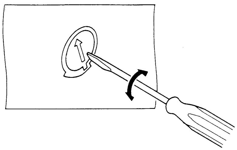
4.1 Adjusting the height of the pressure ring holder
The height of the holder must be adjusted to maintain braking by keeping the appropriate distance between the holder and pressure ring.
With the drawer in the unit, lift the holder manually, and place the positioning tool on the turntable.
If the drawer is in the "out" position, the alminum cap will come in contact with the front chassis and front panel, and will be scratched when the drawer is pushed into the unit.
With a screwdriver, turn the adjustment screw clockwise 2 or 3 turns. Push down the holder several times to confirm that it sinks a few millimeters until it makes contact with the positioning tool. If there is no play between the holder and tool, turn the adjustment screw further until a few millimeters play is obtained.
Turn the adjustment screw counterclockwise until the play between the holder and tool becomes zero.
For optimum adjustment, do not exert excess pressure on the adjustment screw with the screwdriver.
Apply lock paint to the adjustment screw.
Lift the holder with the drawer in the "in" position, and remove the positioning tool.
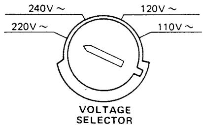
5. VOLTAGE CONVERSION
- EUROPEAN MODEL ONLY
To convert the unit to a different power source voltage, change the position as illustrated in the drawing below.
CAUTION
DISCONNECT POWER SUPPLY CORD FROM AC OUTLET BEFORE CONVERTING VOLTAGE.
Voltage Conversion Chart
Note on safety: Symbol Fire or electrical shock hazard. Only original parts should be used to replace any part marked with symbol Any other component substitution (other than original type), may increase risk of fire or electrical shock hazard.
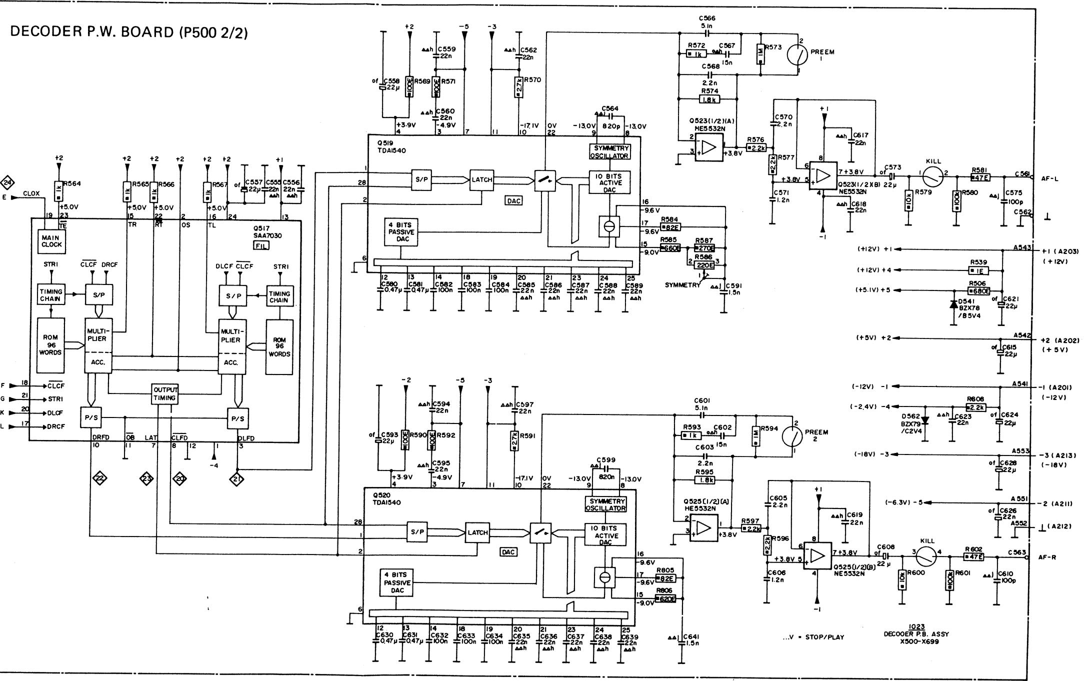
8.1 Servo (P200) Schematic Diagram and Component Locations
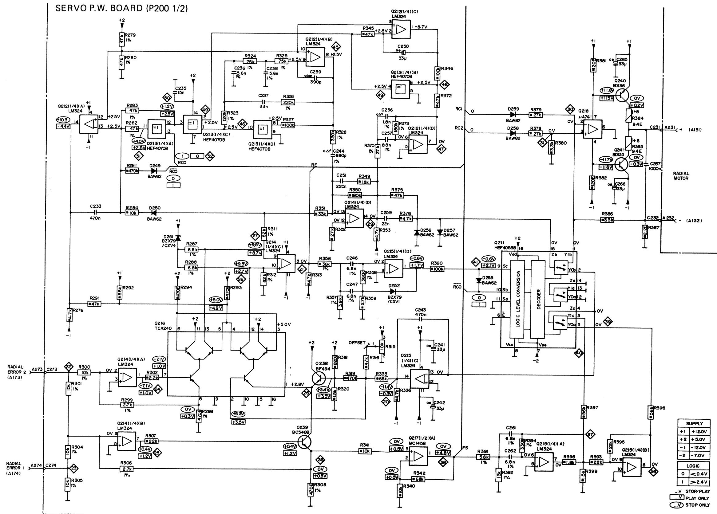
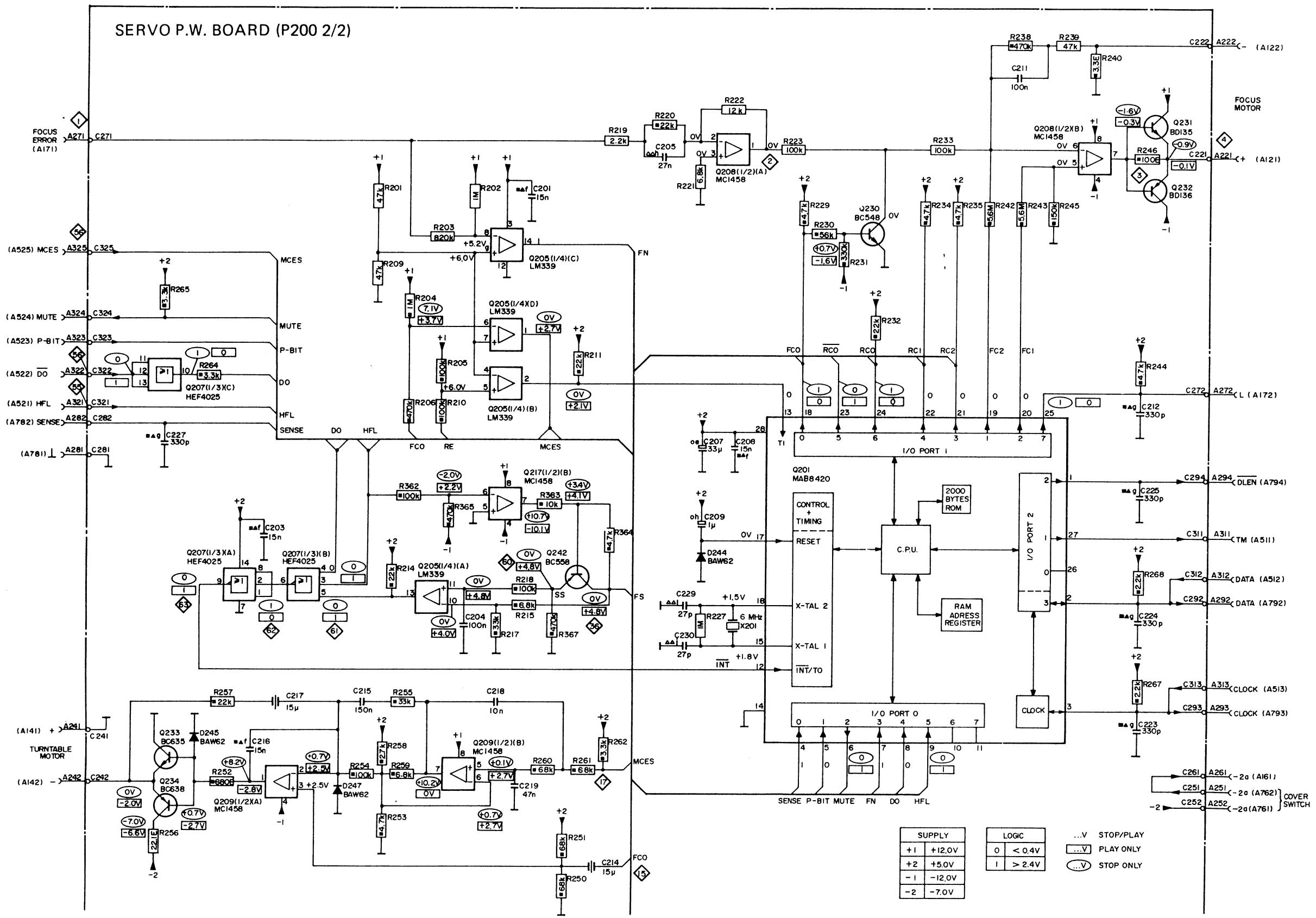
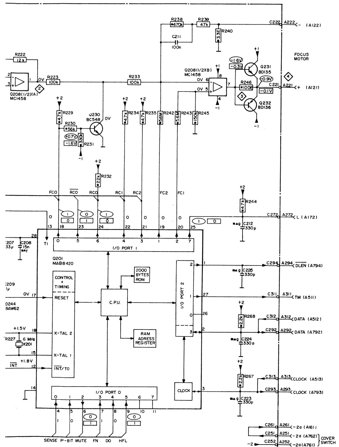
| SUPPLY | LOGIC | ||
| +1 | +12.0V | 0 | < 0.4V |
| +2 | +5.0V | 1 | > 2.4V |
| -1 | -12.0V | ||
| -2 | -7.0V | ||
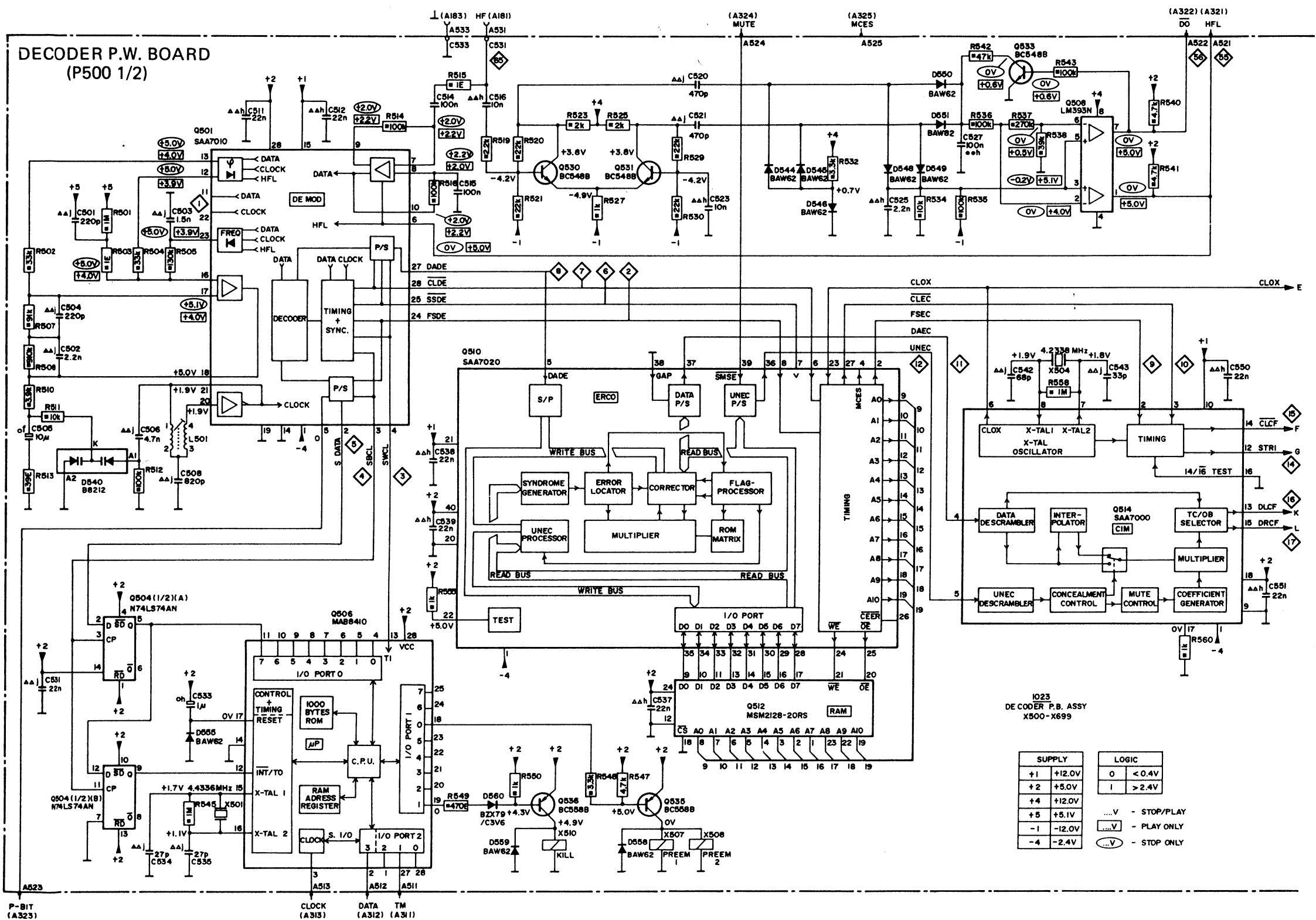
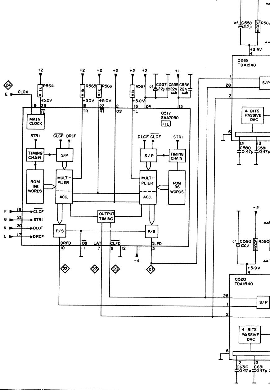
DECODER P.W. BOARD (P500 2/2)

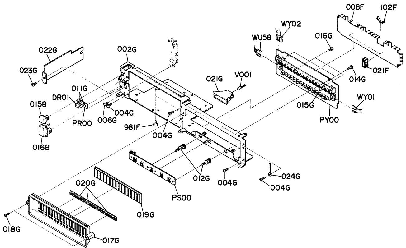
9. EXPLODED VIEW AND PARTS LIST
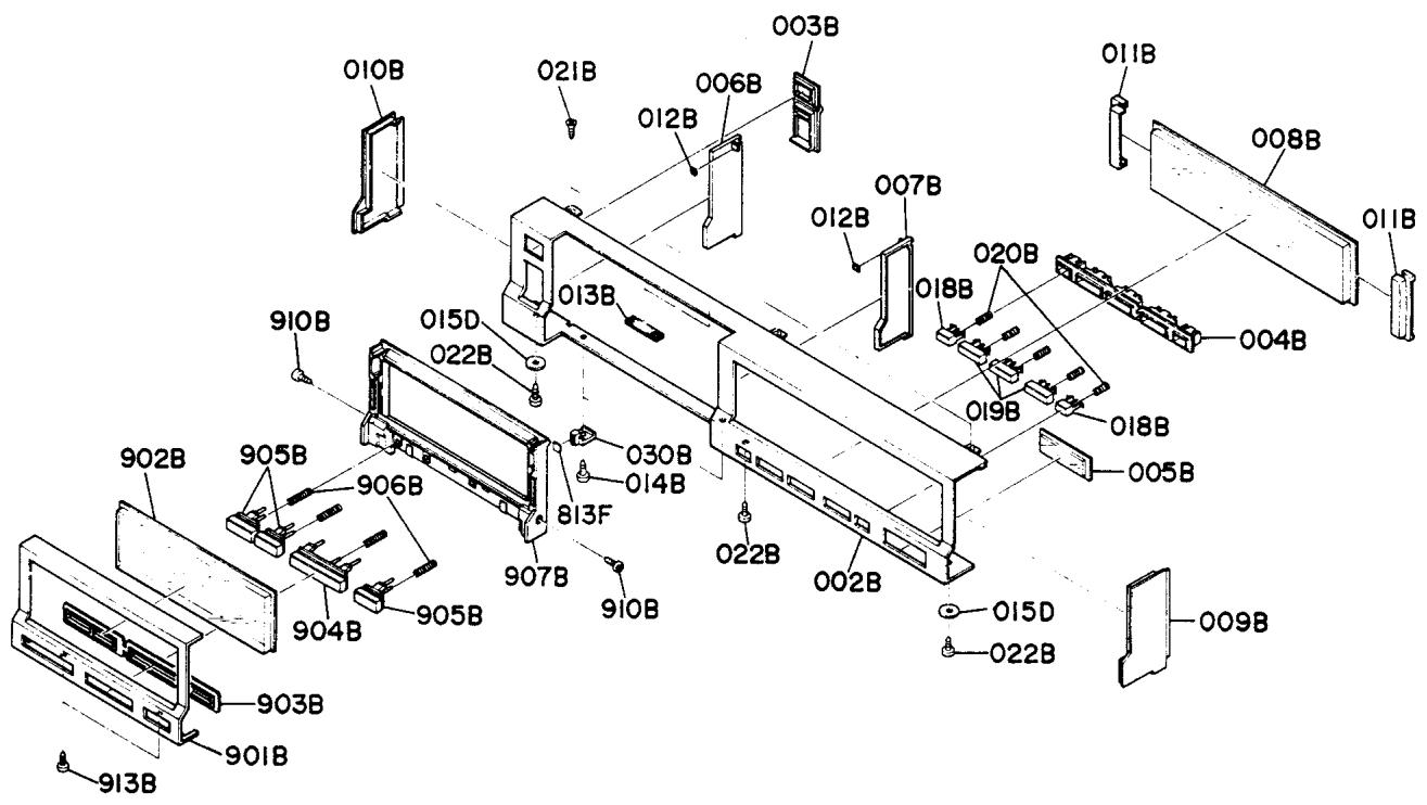
C01-99] Front Panel
(N) : for Europe
(F) : for Japan
| REF. DESIG. | Q'TY | PART NO. | DESCRIPTION | |
| N | F | |||
| A | 1 | 1 | 101K063400 | Front Panel Assembly |
| 002B | 1 | 1 | 101K063010 | Escutcheon, Front Panel |
| 003B | 1 | 1 | 101K259030 | Bushing, Power |
| 004B | 1 | 1 | 101K259010 | Bushing, Function |
| 005B | 1 | 1 | 101K251010 | Badge |
| 006B | 1 | 1 | 101K201020 | Divition, (L) |
| 007B | 1 | 1 | 101K201010 | Divition, (R) |
| 008B | 1 | 1 | 101K158010 | Window |
| 009B | 1 | 1 | 101K067010 | Cap, (R) |
| 010B | 1 | 1 | 101K067020 | Cap, (L) |
| 011B | 2 | 2 | 101K005010 | Clamper |
| 012B | 2 | 2 | 101K056010 | Buffer |
| 013B | 2 | 2 | 101K056030 | Buffer |
| REF. DESIG. | Q'TY | PART NO. | DESCRIPTION | |
| N | F | |||
| 014B | 2 | 2 | 5128030880 | B.H. Tapped Screw B3 x 8 |
| 018B | 2 | 2 | 101K154010 | Knob, Stop/Cancel |
| 019B | 3 | 3 | 101K154020 | Knob |
| 020B | 5 | 5 | 101K115130 | Spring, Knob |
| 021B | 2 | 2 | 5150030680 | F.H. Taptite Screw F3 x 6 |
| 022B | 3 | 3 | 5128030880 | B.H. Tapped Screw B3 x 8 |
| 030B | 2 | 2 | 101K114020 | Stopper |
| 901B | 1 | 1 | 101K063020 | Escutcheon, Door |
| 902B | 1 | 1 | 101K158030 | Window, Door |
| 903B | 1 | 1 | 101K259060 | Bushing |
| 904B | 1 | 1 | 101K154050 | Knob, Play |
| 905B | 3 | 3 | 101K154060 | Knob, FF/REV/Pause |
| 906B | 4 | 4 | 101K115130 | Spring, Knob |
| 907B | 1 | 1 | 101K271040 | Holder, Door |
| 910B | 2 | 2 | 51060305A9 | P.H.M. Screw P3 x 5 |
| 913B | 2 | 2 | 5128030880 | B.H. Tapped Screw B3 x 8 |
| 015D | 2 | 2 | 54110149A0 | Flat Washer, L |
| 813F | 2 | 2 | 101K056060 | Buffer |
(N) : for Europe
(F) : for Japan
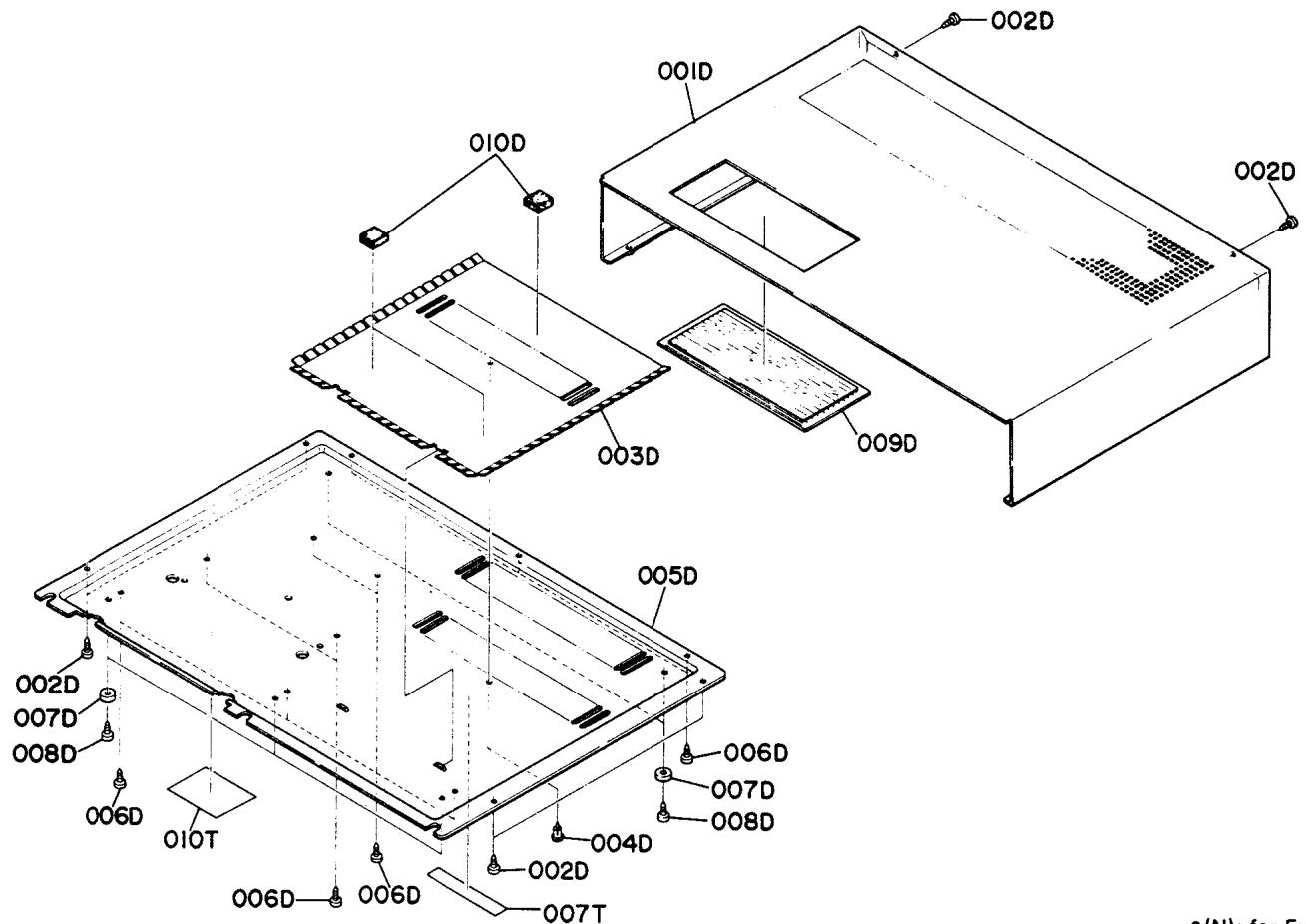
| REF. DESIGN. | Q'TY | PART NO. | DESCRIPTION | ||
| N | F | ||||
| 001D | 1 | 1 | 101K257030 | Lid, Top Cover | |
| 002D | 6 | 6 | 5128030580 | B.H. Tapped Screw | B3 x 5 |
| 003D | 1 | 1 | 101K109030 | Shield | |
| 004D | 1 | 1 | 2912259020 | Bushing | |
| 005D | 1 | 1 | 101K257010 | Lid, Bottom Cover | |
| 006D | 10 | 10 | 5128030580 | B.H. Tapped Screw | B3 x 5 |
| 007D | 5 | 5 | 136T057010 | Leg | |
| 008D | 5 | 5 | 5128030580 | B.H. Tapped Screw | B3 x 5 |
| 009D | 1 | 1 | 101K158020 | Window | |
| 010D | 3 | 3 | 228H056010 | Buffer | |
| REF. DESIGN. | Q'TY | PART NO. | DESCRIPTION | |
| N | F | |||
| 007T | 1 | 1 | 2911861110 | Label, Caution |
| 010T | 101K861030 | Label, Laser Caution | ||
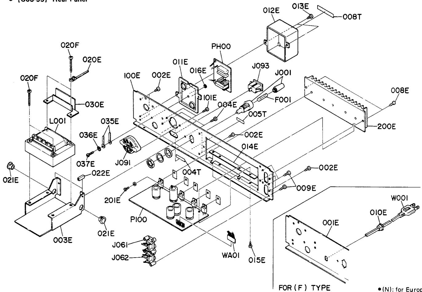
[CO3-99] Rear Panel
FOR(F)TYPE
(N) : for Europe
(F) : for Japan
| REF. DESIG. | Q'TY | PART NO. | DESCRIPTION | ||
| N | F | ||||
| 001E | 1 | 101K053080 | Cover, Rear Panel | ||
| 002E | 6 | 6 | 51280305U0 | B.H. Tapped Screw | B3 x 5 |
| 003E | 1 | 1 | 101K160030 | Bracket, Transformer | |
| 004E | 2 | 2 | 51280305U0 | B.H. Tapped Screw | B3 x 5 |
| 008E | 2 | 2 | 51280308U0 | B.H. Tapped Screw | B3 x 8 |
| 009E | 4 | 4 | 51280308U0 | B.H. Tapped Screw | B3 x 8 |
| 010E | 1 | 1455259030 | Bushing, AC Cord | ||
| 011E | 1 | 1 | 101K064020 | Case, Filter; Bottom | |
| 012E | 1 | 1 | 101K064030 | Case, Filter; Top | |
| 013E | 2 | 2 | 51280310U0 | B.H. Tapped Screw | B3 x 10 |
| 014E | 1 | 1 | 101K120030 | Insulator | |
| 015E | 2 | 2 | 51280310U0 | B.H. Tapped Screw | B3 x 10 |
| 016E | 1 | 1 | 101K056020 | Buffer | |
| 020E | 2 | 2 | 101K005030 | Clamper | |
| 021E | 2 | 2 | 101K259080 | Bushing | |
| 022E | 2 | 2 | 101K259090 | Bushing | |
| 030E | 1 | 101K120040 | Insulator | ||
| 035E | 2 | 2 | 4220005030 | Clamper | |
| 036E | 1 | 1 | 54050300R0 | T.L. Washer, OR | |
| 037E | 1 | 1 | 51280308B0 | B.H. Tapped Screw | B3 x 8 |
| 100E | 1 | 101K053050 | Cover, Rear Panel | ||
| 101E | 2 | 51280308U0 | B.H. Tapped Screw | B3 x 8 | |
| 200E | 1 | 1 | 101K267020 | Heatsink | |
| 201E | 5 | 5 | 51100308S9 | B.H.M. Screw | B3 x 8 |
| REF. DESIG. | Q'TY | PART NO. | DESCRIPTION | |
| N | F | |||
| 020F | 4 | 4 | 51280435U0 | B.H. Tapped Screw B4 x 35 |
| 004T | 1 | 1 | 2112265010 | Indicator |
| 005T | 1 | 4581861010 | Label | |
| 008T | 1 | 1 | 2991861010 | Label |
| ▲F001 | 1 | FS10025800 | Fuse 250mA 250V | |
| ▲F001 | 1 | FS10100600 | Fuse 1A 250V | |
| ▲J001 | 1 | YJ08000290 | Jack, Fuse Holder | |
| ▲J001 | 1 | YT08000300 | Jack, Fuse Holder | |
| J061 | 1 | 1 | YT02020320 | Terminal, RCA Pin (2P) |
| J062 | 1 | 1 | YT02020370 | Terminal, RCA Pin (2P) |
| ▲J091 | 1 | BY05080030 | Voltage Selector | |
| ▲J093 | 1 | YP04000580 | Plug, AC Inlet | |
| ▲L001 | 1 | TS17627020 | Power Transformer | |
| ▲L001 | 1 | TS17627010 | Power Transformer | |
| ▲W001 | 1 | 1 | YC01800190 | A.C. Power Cord |
| WA01 | 1 | 1 | YB00070040 | Connective Cord, (6P) |
(N) : for Europe
(F) : for Japan
| REF. DESIG. | Q'TY | PART NO. | DESCRIPTION | ||
| N | F | ||||
| 0158 | 1 | 1 | 101K154040 | Knob, Open/Close | |
| 016B | 1 | 1 | 101K154030 | Knob, Power | |
| 008F | 1 | 1 | 101K109040 | Shield, Front | |
| 021F | 2 | 2 | 2818056030 | Buffer | |
| 102F | 1 | 1 | 101K259110 | Bushing | |
| 981F | 2 | 2 | 51280305B0 | B.H. Tapped Screw B3 x 5 | |
| 002G | 1 | 1 | 101K105010 | Chassis, Front | |
| 004G | 6 | 6 | 51280305B0 | B.H. Tapped Screw B3 x 5 | |
| 006G | 1 | 1 | 51280305B0 | B.H. Tapped Screw B3 x 5 | |
| 011G | 1 | 1 | 101K118020 | Spacer | |
| 012G | 2 | 2 | 3896101010 | Support | |
| 014G | 2 | 2 | 51280305B0 | B.H. Tapped Screw B3 x 5 | |
| 015G | 1 | 1 | 101K271010 | Holder, LED | |
| 016G | 2 | 2 | 51500306B0 | F.H. Tapped Screw F3 x 6 | |
| 017G | 1 | 1 | 101K280010 | Housing, Display | |
| 018G | 2 | 2 | 51280308B0 | B.H. Tapped Screw B3 x 8 | |
| REF. DESIG. | Q'TY | PART NO. | DESCRIPTION | |
| N | F | |||
| 019G | 1 | 1 | 101K265010 | Indicator, Display |
| 020G | 3 | 3 | 101K265020 | Indicator, Display |
| 021G | 1 | 1 | 101K274010 | Reflector, Lamp |
| 022G | 1 | 1 | 101K120020 | Insulator |
| 023G | 1 | 1 | 51280308B0 | B.H. Tapped Screw B3 x 8 |
| 024G | 1 | 1 | 4220005030 | Clamper |
| V001 | 1 | 1 | IN10080500 | Lamp 60mA 8V |
| DR01 | 1 | 1 | HI10032030 | L.E.D., SLP171D |
| WU58 | 1 | 1 | YB00250170 | Connective Cord, (6P) |
| WY01 | 1 | 1 | YB00240050 | Connective Cord, (6P) |
| WY02 | 1 | 1 | YB00150340 | Connective Cord, (6P) |
- [P02-99] Chassis Assembly and General Parts
(N) : for Europe
(F) : for Japan
| REF. DESIG. | Q'TY | PART NO. | DESCRIPTION | |
| N | F | |||
| 001F | 1 | 1 | 101K105400 | Chassis Assembly, (L) |
| 005F | 2 | 2 | 101K271080 | Holder, LED |
| 006F | 1 | 1 | 101K105020 | Chassis, Center |
| 007F | 1 | 1 | 101K105030 | Chassis, (R) |
| 009F | 1 | 1 | 101K109020 | Sheild, Top |
| 010F | 2 | 2 | 51280305B0 | B.H. Tapped Screw B3 x 5 |
| 011F | 4 | 4 | 51280305B0 | B.H. Tapped Screw B3 x 5 |
| 012F | 1 | 1 | 101K160150 | Bracket |
| 013F | 1 | 1 | 101K160160 | Bracket |
| 014F | 2 | 2 | 51280305B0 | B.H. Tapped Screw B3 x 5 |
| 015F | 1 | 1 | 101K271050 | Holder |
| 016F | 1 | 1 | 51280305B0 | B.H. Tapped Screw B3 x 5 |
| 017F | 1 | 1 | 62030039W0 | Lug, Earth |
| 018F | 2 | 2 | 51280305B0 | B.H. Tapped Screw B3 x 5 |
| 030F | 1 | 1 | 101K109070 | Shield, Rear |
| 031F | 1 | 1 | 101K259110 | Bushing |
| 032F | 1 | 1 | 51280305B0 | B.H. Tapped Screw B3 x 5 |
| 033F | 1 | 1 | 62030049W0 | Lug, Earth |
| 034F | 1 | 1 | 4220005030 | Clamper |
| 035F | 3 | 3 | 228H056010 | Buffer |
| 100F | 1 | 1 | 101K259100 | Bushing |
| 101F | 1 | 1 | 101K259090 | Bushing |
| 103F | 1 | 1 | 101K259110 | Bushing |
| 811F | 1 | 1 | 101K056050 | Buffer |
| 970F | 2 | 2 | 51280305B0 | B.H. Tapped Screw B3 x 5 |
| 971F | 1 | 1 | 101K002050 | Arm, Lock |
| 972F | 1 | 1 | 64000300R0 | RG Ring, E Type |
| 973F | 1 | 1 | 101K115080 | Spring, Lock Arm |
| REF. DESIGN. | Q'TY | PART NO. | DESCRIPTION | |
| N | F | |||
| 005G | 1 | 1 | 101K160050 | Bracket, Power Switch |
| 007G | 4 | 4 | 51100305A9 | B.H.M. Screw B3 x 5 |
| 008G | 1 | 1 | 403H120010 | Insulator |
| 009G | 1 | 1 | 101K118010 | Spacer |
| 010G | 1 | 1 | 101K271070 | Holder |
| 013G | 1 | 1 | 203H101010 | Support |
| C001 | 6 | 6 | DC18202060 | Feedthru Cap. 2000p F |
| C006 | ||||
| W851 | 1 | 1 | YB00150360 | Connective Cord, (2P) |
| W852 | 1 | 1 | YB00500310 | Connective Cord, (2P) |
| W853 | 1 | 1 | YB00700180 | Connective Cord, (4P) |
| W854 | 1 | 1 | YB00650030 | Connective Cord, (5P) |
| W855 | 1 | 1 | YB00580010 | Connective Cord, (3P) |
| WA02 | 1 | 1 | YB00180160 | Connective Cord |
| WA03 | 1 | 1 | YB00170060 | Connective Cord |
| WA04 | 1 | 1 | YB00170070 | Connective Cord |
| WA05 | 1 | 1 | YB00170080 | Connective Cord |
| WU51 | 1 | 1 | YB00380030 | Connective Cord, (8P) |
| WU52 | 1 | 1 | YB00380030 | Connective Cord, (8P) |
| WU53 | 1 | 1 | YB00380030 | Connective Cord, (8P) |
| WU54 | 1 | 1 | YB00380040 | Connective Cord, (6P) |
| WU55 | 1 | 1 | YB00300640 | Connective Cord, (3P) |
| WU56 | 1 | 1 | YB00400340 | Connective Crod, (4P) |
| WU58 | 1 | 1 | YB00250170 | Connective Cord, (6P) |
| WU59 | 1 | 1 | YB00130080 | Connective Cord, (3P) |
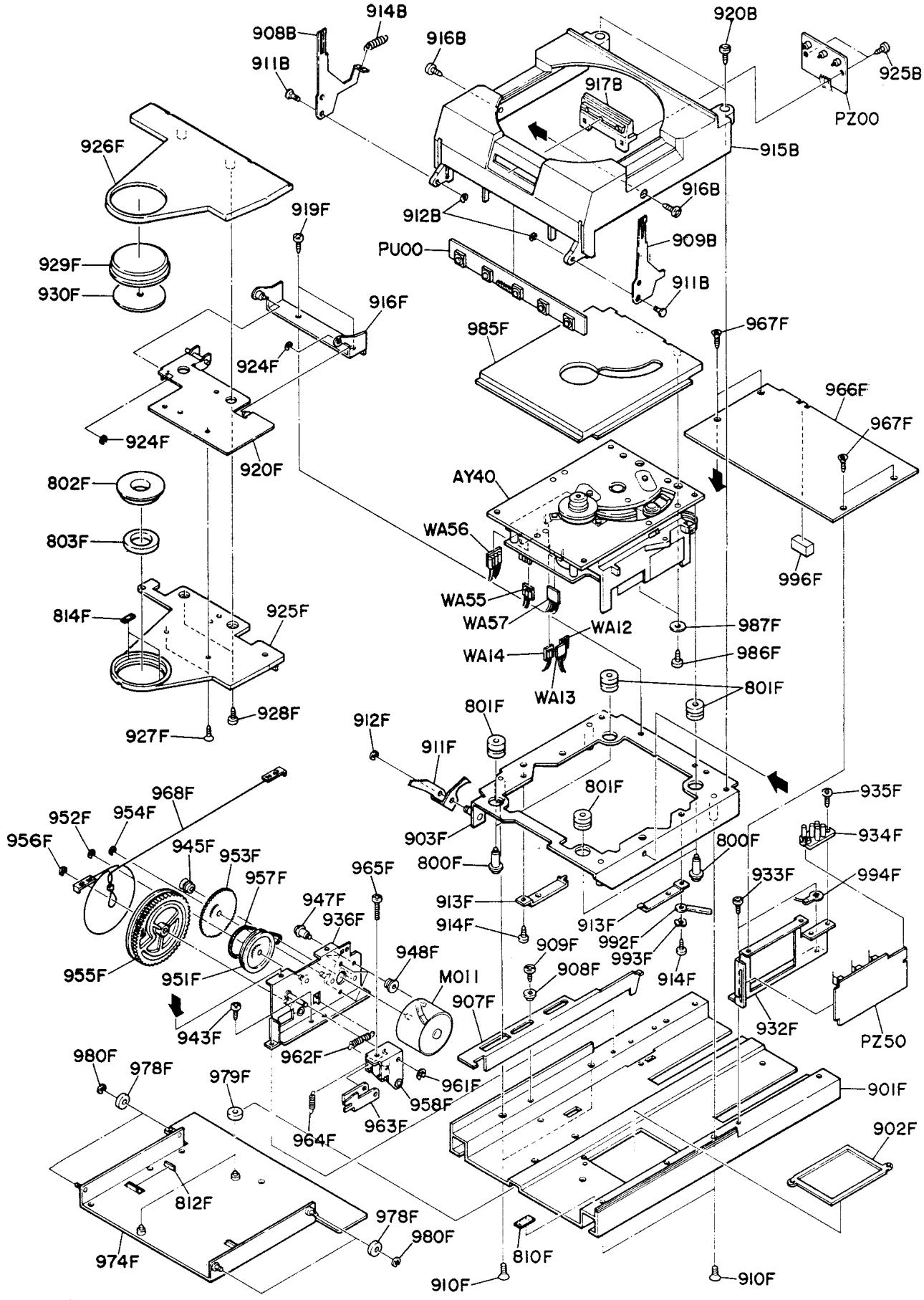
| REF. DESIG. | Q'TY | PART NO. | DESCRIPTION | ||
| N | F | ||||
| 908B | 1 | 1 | 101K160120 | Bracket, Door (L) | |
| 909B | 1 | 1 | 101K160130 | Bracket, Door (R) | |
| 911B | 2 | 2 | 101K112120 | Shaft, Door | |
| 912B | 2 | 2 | 64000300R0 | RG Ring, E Type | |
| 914B | 1 | 1 | 101K115120 | Spring | |
| 915B | 1 | 1 | 101K064010 | Case, Mecha | |
| 916B | 2 | 2 | 51100308A9 | B.H.M. Screw | B3 x 8 |
| 917B | 1 | 1 | 101K160020 | Bracket, LED | |
| 920B | 2 | 2 | 51280308B0 | B.H. Tapped Screw | B3 x 8 |
| 925B | 2 | 2 | 51280308B0 | B.H. Tapped Screw | B3 x 8 |
| 800F | 4 | 4 | 101K112170 | Shaft | |
| 801F | 4 | 4 | 101K259050 | Bushing, Mecha | |
| 802F | 1 | 1 | 101K353010 | Ring | |
| 803F | 1 | 1 | 101K252010 | Pad | |
| 810F | 1 | 1 | 101K056040 | Buffer | |
| 812F | 1 | 1 | 101K056050 | Buffer | |
| 814F | 2 | 2 | 101K056070 | Buffer | |
| 901F | 1 | 1 | 101K051020 | Guide | |
| 902F | 1 | 1 | 101K067040 | Cap | |
| 903F | 1 | 1 | 101K160420 | Bracket Assembly, Mecha | |
| 907F | 1 | 1 | 101K354020 | Lever, Door Open | |
| 908F | 1 | 1 | 101K055010 | Collar | |
| 909F | 1 | 1 | 51280308B0 | B.H. Tapped Screw | B3 x 8 |
| 910F | 4 | 4 | 51040308A9 | F.H.M. Screw | F3 x 8 |
| 911F | 1 | 1 | 101K002040 | Arm, Door Open | |
| 912F | 1 | 1 | 64000300R0 | RG Ring, E Type | |
| 913F | 2 | 2 | 101K104020 | Retainer | |
| 914F | 2 | 2 | 51280305B0 | B.H. Tapped Screw | B3 x 5 |
| 916F | 1 | 1 | 101K104400 | Retainer Assembly | |
| 919F | 2 | 2 | 51280305B0 | B.H. Tapped Screw | B3 x 5 |
| 920F | 1 | 1 | 101K160400 | Bracket, Assembly | |
| 924F | 2 | 2 | 64000300R0 | RG Rign, E Type | |
| 925F | 1 | 1 | 101K271030 | Holder, Pressure Ring | |
| 926F | 1 | 1 | 101K053070 | Cover, Pressure Ring | |
| 927F | 2 | 2 | 51040305A9 | F.H.M. Screw | F3 x 5 |
| 928F | 2 | 2 | 51280308B0 | B.H. Tapped Screw | B3 x 8 |
| 929F | 1 | 1 | 101K067030 | Cap, Pressure Ring | |
| 930F | 1 | 1 | 101K263020 | Brake | |
| 932F | 1 | 1 | 101K160110 | Bracket | |
| 933F | 2 | 2 | 51280308B0 | B.H. Tapped Screw | B3 x 8 |
| 934F | 1 | 1 | 101K271050 | Holder | |
| 935F | 1 | 1 | 51280308B0 | B.H. Tapped Screw | B3 x 8 |
| 936F | 1 | 1 | 101K160410 | Bracket Assembly, Motor | |
| 943F | 2 | 2 | 51280308B0 | B.H. Tapped Screw | B3 x 8 |
| 945F | 1 | 1 | 101K262020 | Pulley, Motor | |
| 947F | 3 | 3 | 4367112150 | Shaft, Motor | |
| 948F | 3 | 3 | 313Y259010 | Bushing | |
| 951F | 1 | 1 | 101K262010 | Pulley, Idler | |
| 952F | 1 | 1 | 64001500R0 | RG Ring, E Type | |
| 953F | 1 | 1 | 101K058010 | Gear, Idler | |
| 954F | 1 | 1 | 64001500R0 | RG Ring, E Type | |
| 955F | 1 | 1 | 101K058030 | Gear, Drive | |
| 956F | 1 | 1 | 64000200R0 | RG Ring, E Type | |
| 957F | 1 | 1 | 101K264010 | Belt, Drive | |
| 958F | 1 | 1 | 101K002400 | Arm, Drive Assembly | |
| REF. DESIG. | Q'TY | PART NO. | DESCRIPTION | |
| N | F | |||
| 961F | 1 | 1 | 64000300R0 | RG Ring, E Type |
| 962F | 1 | 1 | 101K115090 | Spring |
| 963F | 1 | 1 | 101K002030 | Arm |
| 964F | 1 | 1 | 101K115070 | Spring |
| 965F | 1 | 1 | 51100315A9 | B.H.M. Screw B3 x 15 |
| 966F | 1 | 1 | 101K257020 | Lid, Mecha |
| 967F | 4 | 4 | 51500306B0 | F.H. Taptite Screw F3 x 6 |
| 968F | 1 | 1 | 101K125500 | Joint, (K) |
| 974F | 1 | 1 | 101K051400 | Guide Assembly, Rai |
| 978F | 4 | 4 | 101K358010 | Roller, B |
| 979F | 2 | 2 | 101K358020 | Roller, A |
| 980F | 4 | 4 | 64000200R0 | RG Ring, E Type |
| 985F | 1 | 1 | 101K053060 | Cover, Mecha |
| 986F | 2 | 2 | 51380205A0 | P.H. Tapped Screw P2 x 5 |
| 987F | 2 | 2 | 54022601A0 | Flat Washer, P. |
| 992F | 1 | 1 | 4220005020 | Clamper |
| 993F | 1 | 1 | 54050300R0 | T.L. Washer, OR |
| 994F | 1 | 1 | 62030039W0 | Lug, Earth |
| 996F | 1 | 1 | 2818056030 | Buffer |
| AY40 | 1 | 1 | AY101K0040 | Sub Chassis Assembly |
| M011 | 1 | 1 | MM01500020 | D.C. Motor, Drive |
| WA12 | 1 | 1 | YB00209010 | Connective Cord, (2P) |
| WA13 | 1 | 1 | YB00219010 | Connective Cord, (2P) |
| WA14 | 1 | 1 | YB00229010 | Connective Cord, (2P) |
| WA55 | 1 | 1 | YB00279010 | Connective Cord, (3P) |
| WA56 | 1 | 1 | YB00259010 | Connective Cord, (4P) |
| WA57 | 1 | 1 | YB00279020 | Connective Cord, (4P) |
| 1 | 1 | QR11718120 | Pre-Amp. + Laser P.W. Board Assembly | |
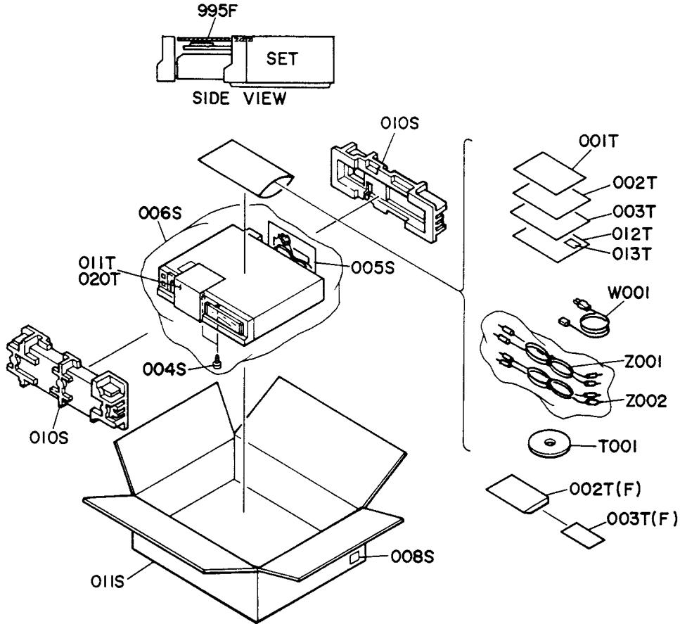
(N) : for Europe
(F) : for Japan
| REF. DESIG. | Q'TY | PART NO. | DESCRIPTION | |
| N | F | |||
| 004S | 2 | 2 | 51400350Y0 | B.H. Tapped Screw B3 x 50 |
| 005S | 1 | 2864804010 | Sleeve | |
| 006S | 1 | 1 | 9090808030 | Polyethylene Sheet |
| 008S | 4 | 9526019060 | Serial No. Card | |
| 008S | 4 | 9526019040 | Serial No. Card | |
| 010S | 1 | 1 | 101K809030 | Cushion, Front/Rear |
| 011S | 1 | 1 | 101K801030 | Packing Case |
| 001T | 1 | 101K851310 | Instructions | |
| 001T | 1 | 101K851110 | Instructions | |
| 002T | 1 | 101K851320 | Instructions, Spec | |
| 002T | 1 | 9631000130 | Guarantee Card | |
| 003T | 1 | 101K856010 | Circuit Diagram | |
| 003T | 1 | 128T854010 | Guarantee Card | |
| 011T | 1 | 101K861040 | Label, Transportation | |
| 012T | 1 | 9611000050 | User's Card | |
| 013T | 1 | 9540000010 | License | |
| 020T | 1 | 101K861050 | Label, Transportation | |
| REF. DESIG. | Q'TY | PART NO. | DESCRIPTION | |
| N | F | |||
| T001 | 1 | 1 | UD01200020 | Disc, Demo |
| W001 | 1 | ZC01805010 | A.C. Power Cord | |
| Z001 | 1 | 1 | ZD01000240 | Connective Cord, Audio Out |
| Z002 | 1 | 1 | ZD01000220 | Connective Cord, Remocon |
| 995F | 1 | 1 | 101K269010 | Protector |
| REF. DESIG. | Q'TY | PART NO. | DESCRIPTION | |||
| N | F | |||||
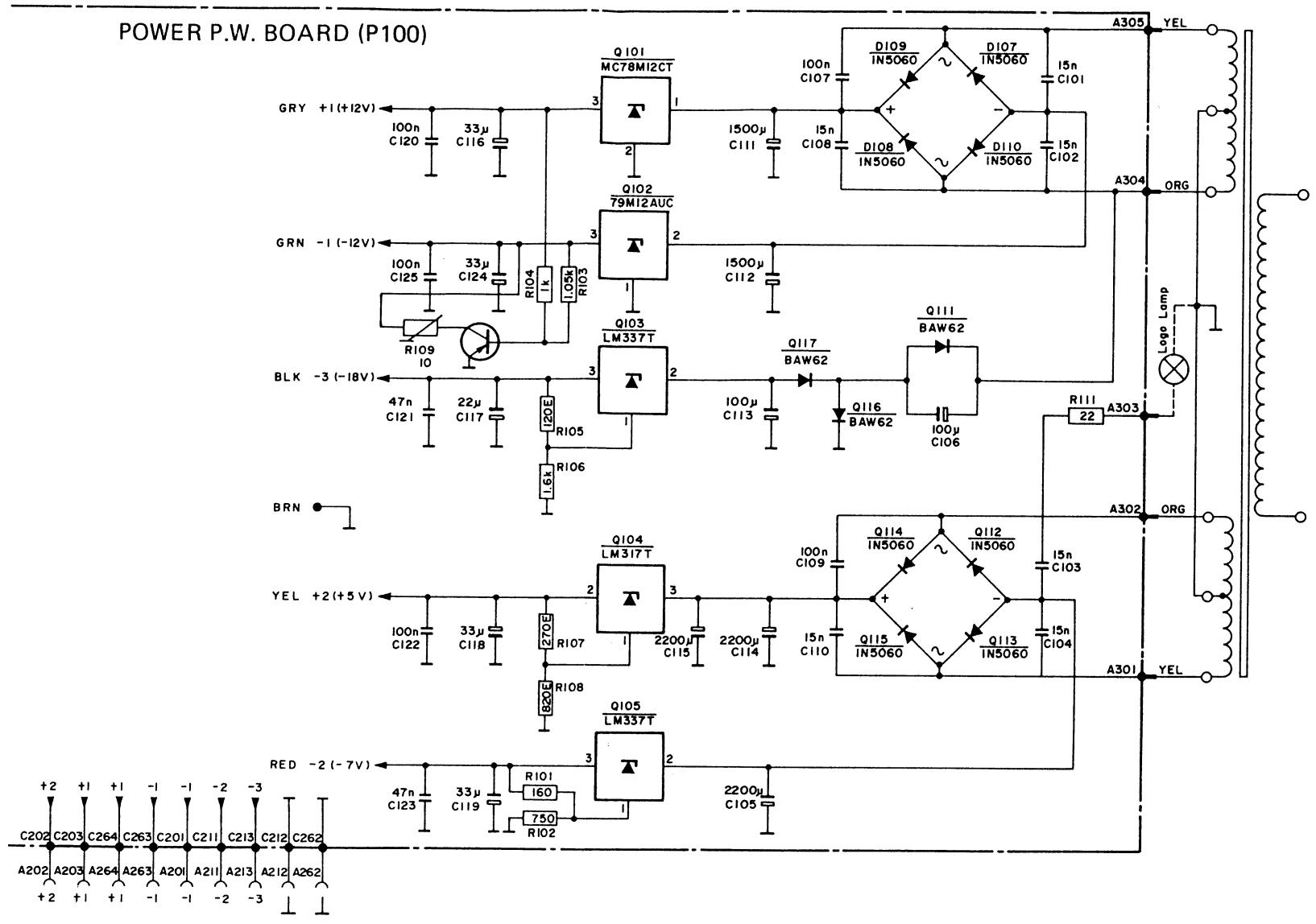
| P100 | 1 | 1 | YK101K1220ZZ101K8220 | P100-POWER SUPPLYCIRCUIT BOARDP.W. Board, Power SupplyP.W. Board Assembly | ||
| C101 | 1 | 1 | DK18153300 | Ceramic 0.015μF | ||
| C102 | 1 | 1 | DK18153300 | Ceramic 0.015μF | ||
| C103 | 1 | 1 | DK18153300 | Ceramic 0.015μF | ||
| C104 | 1 | 1 | DK18153300 | Ceramic 0.015μF | ||
| C105 | 1 | 1 | EA22801630 | Elect 2200μF | 16V | |
| C106 | 1 | 1 | OA47702510 | Elect 470μF | 25V | |
| C107 | 1 | 1 | DF17104350 | Film 0.1μF ±20% | ||
| C108 | 1 | 1 | DK18153300 | Ceramic 0.015μF | ||
| C109 | 1 | 1 | DF17104350 | Film 0.1μF ±20% | ||
| C110 | 1 | 1 | DK18153300 | Ceramic 0.015μF | ||
| C111 | 1 | 1 | OA33802510 | Elect 3300μF | 25V | |
| C112 | 1 | 1 | OA33802510 | Elect 3300μF | 25V | |
| C113 | 1 | 1 | OA47702510 | Elect 470μF | 25V | |
| C114 | 1 | 1 | OA33801610 | Elect 3300μF | 16V | |
| C115 | 1 | 1 | OA33801610 | Elect 3300μF | 16V | |
| C116 | 1 | 1 | OA47601610 | Elect 47μF | 16V | |
| C117 | 1 | 1 | EA22602530 | Elect 22μF | 25V | |
| C118 | 1 | 1 | EA33601630 | Elect 33μF | 16V | |
| C119 | 1 | 1 | EA33601630 | Elect 33μF | 16V | |
| C120 | 1 | 1 | DF16104510 | Film 0.1μF ±10% | ||
| C121 | 1 | 1 | DF16104510 | Film 0.1μF ±10% | ||
| C122 | 1 | 1 | DF16104510 | Film 0.1μF ±10% | ||
| C123 | 1 | 1 | DK18473320 | Ceramic 0.047μF | ||
| C124 | 1 | 1 | OA47601610 | Elect 47μF | 16V | |
| C125 | 1 | 1 | DF16104510 | Film 0.1μF ±10% | ||
| P100-RESISTORS(All Resistors are ±5% and %W) | ||||||
| R101 | 1 | 1 | GD05121140 | 120Ω | ||
| R102 | 1 | 1 | GD05561140 | 560Ω | ||
| R103 | 1 | 1 | GD05102140 | 1KΩ | ||
| R104 | 1 | 1 | GD05102140 | 1KΩ | ||
| R107 | 1 | 1 | GD05271140 | 270Ω | ||
| R108 | 1 | 1 | GD05821140 | 820Ω | ||
| R109 | 1 | 1 | HH00001490 | Thermistor | ||
| R110 | 1 | 1 | GD05470140 | 47Ω | ||
| R111 | 1 | 1 | GA05220020 | 22Ω 2W | ||
| P100-SEMICONDUCTORS | ||||||
| D107 | 1 | 1 | HD20009290 | Diode S2V20 | ||
| D108 | 1 | 1 | HD20009290 | Diode S2V20 | ||
| D109 | 1 | 1 | HD20009290 | Diode S2V20 | ||
| D110 | 1 | 1 | HD20009290 | Diode S2V20 | ||
| D111 | 1 | 1 | HD20003210 | Diode 1S2471 | ||
| D112 | 1 | 1 | HD20009290 | Diode S2V20 | ||
| D113 | 1 | 1 | HD20009290 | Diode S2V20 | ||
| D114 | 1 | 1 | HD20009290 | Diode S2V20 | ||
| D115 | 1 | 1 | HD20009290 | Diode S2V20 | ||
| D116 | 1 | 1 | HD20003210 | Diode 1S2471 | ||
| D117 | 1 | 1 | HD20003210 | Diode 1S2471 | ||
| Q101 | 1 | 1 | HC10043060 | IC μPC7812H | ||
| Q102 | 1 | 1 | HC10044060 | IC μPC7912H | ||
| Q103 | 1 | 1 | HC10079060 | IC μPC7918H | ||
| Q104 | 1 | 1 | HC10013360 | IC LM317T | ||
| Q105 | 1 | 1 | HC10014360 | IC LM337T | ||
| Q106 | 1 | 1 | HT106831D0 | Transistor 2SA683(S) | ||
| REF. DESIG. | QTY | PART NO. | DESCRIPTION | |||
| N | F | |||||
| P100-MISCELLANEOUSPlug, (6P) | ||||||
| J101 | 1 | 1 | YP06002420 | Plug, (6P)Connective Cord, (6P) | ||
| WA01 | 1 | 1 | YB00070040 | |||
| P200-SERVO CIRCUIT BOARD | ||||||
| P200 | 1 | 1 | YG101K0010 | P.W. Board, Servo | ||
| ZZ101K8010 | P.W. Board Assembly | |||||
| P200-CAPACITORS | ||||||
| C201 | 1 | 1 | DA17103010 | Ceramic | 0.01μF ±20% | |
| C203 | 1 | 1 | DA17103010 | Ceramic | 0.01μF ±20% | |
| C204 | 1 | 1 | DF15104350 | Film | 0.1μF ±5% | |
| C205 | 1 | 1 | DF74273010 | Film | 0.027μF ±2% | |
| C207 | 1 | 1 | EA33601630 | Elect | 33μF 16V | |
| C208 | 1 | 1 | DA17103010 | Ceramic | 0.01μF ±20% | |
| C209 | 1 | 1 | EA10505030 | Elect | 1μF 50V | |
| C210 | 1 | 1 | DD15270370 | Ceramic | 27pF ±5% | |
| C211 | 1 | 1 | DF15104350 | Film | 0.1μF ±5% | |
| C212 | 1 | 1 | DK16331300 | Ceramic | 330pF ±10% | |
| C213 | 1 | 1 | DD15270370 | Ceramic | 27pF ±5% | |
| C214 | 1 | 1 | EQ22601630 | Elect | 22μF 16V | |
| C215 | 1 | 1 | DF15154350 | Film | 0.15μF ±5% | |
| C216 | 1 | 1 | DA17103010 | Ceramic | 0.01μF ±20% | |
| C217 | 1 | 1 | EQ22601630 | Elect | 22μF 16V | |
| C218 | 1 | 1 | DF15103350 | Film | 0.01μF ±5% | |
| C219 | 1 | 1 | DF15473350 | Film | 0.047μF ±5% | |
| C223 | 1 | 1 | DA16331010 | Ceramic | 330pF ±10% | |
| C224 | 1 | 1 | DA16331010 | Ceramic | 330pF ±10% | |
| C225 | 1 | 1 | DK16331300 | Ceramic | 330pF ±10% | |
| C228 | 1 | 1 | DF15104350 | Film | 0.1μF ±5% | |
| C227 | 1 | 1 | DA16331010 | Ceramic | 330pF ±10% | |
| C233 | 1 | 1 | DF15474350 | Film | 0.47μF ±5% | |
| C235 | 1 | 1 | DA17103010 | Ceramic | 0.01μF ±20% | |
| C236 | 1 | 1 | DF74562010 | Film | 5600pF ±2% | |
| C237 | 1 | 1 | DF15333350 | Film | 0.033μF ±5% | |
| C238 | 1 | 1 | DF74562010 | Film | 5600pF ±2% | |
| C239 | 1 | 1 | DF55391090 | Film | 390pF ±5% | |
| C241 | 1 | 1 | EA33601630 | Elect | 33μF 16V | |
| C242 | 1 | 1 | EA33601630 | Elect | 33μF 16V | |
| C243 | 1 | 1 | DF15474350 | Film | 0.47μF ±5% | |
| C244 | 1 | 1 | DF55681090 | Film | 680pF ±5% | |
| C246 | 1 | 1 | DF74682010 | Film | 6800pF ±2% | |
| C247 | 1 | 1 | DF74682010 | Film | 6800pF ±2% | |
| C250 | 1 | 1 | EA33601630 | Elect | 33μF 16V | |
| C251 | 1 | 1 | DF15224350 | Film | 0.22μF ±5% | |
| C256 | 1 | 1 | DF74182010 | Film | 1800pF ±2% | |
| C257 | 1 | 1 | DF74682010 | Film | 6800pF ±2% | |
| C259 | 1 | 1 | DF15223350 | Film | 0.022μF ±5% | |
| C261 | 1 | 1 | DF74682010 | Film | 6800pF ±2% | |
| C262 | 1 | 1 | DF14682010 | Film | 6800pF ±2% | |
| C265 | 1 | 1 | EA33601630 | Elect | 33μF 16V | |
| C266 | 1 | 1 | EA33601630 | Elect | 33μF 16V | |
| C267 | 1 | 1 | DF15105350 | Film | 1μF ±5% | |
| REF. DESIG. | Q'TY | PART NO. | DESCRIPTION | |
| N | F | |||
| P200-RESISTORS(All Resistors are ±5% and 1/4W) | ||||
| R201 | 1 | 1 | GM21447520 | 47.5KΩ |
| R202 | 1 | 1 | GM21410040 | 1MΩ |
| R203 | 1 | 1 | GM21482530 | 825KΩ |
| R204 | 1 | 1 | GD05105140 | 1MΩ |
| R205 | 1 | 1 | GD05104140 | 100KΩ |
| R206 | 1 | 1 | GD05474140 | 470KΩ |
| R209 | 1 | 1 | GM21447520 | 47.5KΩ |
| R210 | 1 | 1 | GD05104140 | 100KΩ |
| R211 | 1 | 1 | GD05223140 | 22KΩ |
| R214 | 1 | 1 | GD05223140 | 22KΩ |
| R215 | 1 | 1 | GD05682140 | 6.8KΩ |
| R216 | 1 | 1 | GD05104140 | 100KΩ |
| R217 | 1 | 1 | GD05333140 | 33KΩ |
| R219 | 1 | 1 | GM21422110 | 2.21KΩ |
| R220 | 1 | 1 | GM21422110 | 2.21KΩ |
| R221 | 1 | 1 | GD05682140 | 6.8KΩ |
| R222 | 1 | 1 | GM21412120 | 12.1KΩ |
| R223 | 1 | 1 | GM21410030 | 100KΩ |
| R227 | 1 | 1 | GD05105140 | 1MΩ |
| R229 | 1 | 1 | GD05472140 | 4.7KΩ |
| R230 | 1 | 1 | GD05563140 | 56KΩ |
| R231 | 1 | 1 | GD05334140 | 330KΩ |
| R233 | 1 | 1 | GM21410030 | 100KΩ |
| R234 | 1 | 1 | GD05472140 | 4.7KΩ |
| R235 | 1 | 1 | GD05472140 | 4.7KΩ |
| R238 | 1 | 1 | GD05474140 | 470KΩ |
| R239 | 1 | 1 | GD05473140 | 47KΩ |
| R240 | 1 | 1 | GD05033140 | 3.3Ω |
| R242 | 1 | 1 | GD05565140 | 5.6MΩ |
| R243 | 1 | 1 | GD05565140 | 5.6MΩ |
| R244 | 1 | 1 | GD05472140 | 4.7KΩ |
| R245 | 1 | 1 | GD05154140 | 150KΩ |
| R246 | 1 | 1 | GD05101140 | 100Ω |
| R250 | 1 | 1 | GD05683140 | 68KΩ |
| R251 | 1 | 1 | GD05683140 | 68KΩ |
| R252 | 1 | 1 | GD05681140 | 680Ω |
| R253 | 1 | 1 | GD05472140 | 4.7KΩ |
| R254 | 1 | 1 | GD05104140 | 100KΩ |
| R255 | 1 | 1 | GD05333140 | 33KΩ |
| R256 | 1 | 1 | GA05220020 | 22Ω 2W |
| R257 | 1 | 1 | GD05223140 | 22KΩ |
| R258 | 1 | 1 | GD05272140 | 2.7KΩ |
| R259 | 1 | 1 | GD05682140 | 6.8KΩ |
| R260 | 1 | 1 | GD05683140 | 68KΩ |
| R261 | 1 | 1 | GD05683140 | 68KΩ |
| R262 | 1 | 1 | GD05332140 | 3.3KΩ |
| R264 | 1 | 1 | GD05332140 | 3.3KΩ |
| R265 | 1 | 1 | GD05332140 | 3.3KΩ |
| R267 | 1 | 1 | GD05222140 | 2.2KΩ |
| R268 | 1 | 1 | GD05222140 | 2.2KΩ |
| R276 | 1 | 1 | GD05472140 | 4.7KΩ |
| R279 | 1 | 1 | GM21447520 | 47.5KΩ |
| R280 | 1 | 1 | GM21447520 | 47.5KΩ |
| R281 | 1 | 1 | GD05474140 | 470KΩ |
| R282 | 1 | 1 | GM21447520 | 47.5KΩ |
| R283 | 1 | 1 | GM21447520 | 47.5KΩ |
| R284 | 1 | 1 | GD05103140 | 10KΩ |
| R285 | 1 | 1 | GD05223140 | 22KΩ |
| R287 | 1 | 1 | GM21468110 | 6.81KΩ |
| R288 | 1 | 1 | GM21468110 | 6.81KΩ |
| REF. DESIGN. | Q'TY | PART NO. | DESCRIPTION | |
| N | F | |||
| R291 | 1 | 1 | GD05473140 | 47KΩ |
| R292 | 1 | 1 | GD05683140 | 68KΩ |
| R293 | 1 | 1 | GD05471140 | 470Ω |
| R294 | 1 | 1 | GD05471140 | 470Ω |
| R298 | 1 | 1 | GM21447500 | 475Ω |
| R299 | 1 | 1 | GM21426710 | 2.67KΩ |
| R300 | 1 | 1 | GM21410020 | 10KΩ |
| R301 | 1 | 1 | GM21410020 | 10KΩ |
| R301 | 1 | 1 | GD05222140 | 2.2KΩ |
| R304 | 1 | 1 | GM21410020 | 10KΩ |
| R305 | 1 | 1 | GM21410020 | 10KΩ |
| R306 | 1 | 1 | GM21426710 | 2.67KΩ |
| R307 | 1 | 1 | GD05222140 | 2.2KΩ |
| R308 | 1 | 1 | GM21447500 | 475Ω |
| R311 | 1 | 1 | GM21482520 | 82.5KΩ |
| R312 | 1 | 1 | GM21482520 | 82.5KΩ |
| R313 | 1 | 1 | GD05472140 | 4.7KΩ |
| R315 | 1 | 1 | RA01030070 | 10KΩ, Trimming |
| R316 | 1 | 1 | GD05473140 | 47KΩ |
| R318 | 1 | 1 | GD05821140 | 820Ω |
| R319 | 1 | 1 | GD05471140 | 470Ω |
| R320 | 1 | 1 | GD05152140 | 1.5KΩ |
| R323 | 1 | 1 | GM21412130 | 121KΩ |
| R324 | 1 | 1 | GM21475020 | 75KΩ |
| R325 | 1 | 1 | GM21475020 | 75KΩ |
| R826 | 1 | 1 | GM21422130 | 221KΩ |
| R327 | 1 | 1 | GD05104140 | 100KΩ |
| R328 | 1 | 1 | GM21433230 | 332KΩ |
| R335 | 1 | 1 | GD05683140 | 68KΩ |
| R336 | 1 | 1 | GD05472140 | 4.7KΩ |
| R340 | 1 | 1 | GD05103140 | 10KΩ |
| R341 | 1 | 1 | GD05103140 | 10KΩ |
| R342 | 1 | 1 | GD05683140 | 68KΩ |
| R345 | 1 | 1 | GD05473140 | 47KΩ |
| R346 | 1 | 1 | GD05473140 | 47KΩ |
| R349 | 1 | 1 | GD05183140 | 18KΩ |
| R350 | 1 | 1 | GD05184140 | 180KΩ |
| R351 | 1 | 1 | GD05333140 | 33KΩ |
| R352 | 1 | 1 | GD05273140 | 27KΩ |
| R353 | 1 | 1 | GD05472140 | 4.7KΩ |
| R356 | 1 | 1 | GM21435620 | 35.6KΩ |
| R357 | 1 | 1 | GM21439210 | 3.92KΩ |
| R358 | 1 | 1 | GM21435630 | 356KΩ |
| R359 | 1 | 1 | GD05272140 | 2.7KΩ |
| R360 | 1 | 1 | GD05104140 | 100KΩ |
| R362 | 1 | 1 | GD05104140 | 100KΩ |
| R363 | 1 | 1 | GD05103140 | 10KΩ |
| R364 | 1 | 1 | GD05472140 | 4.7KΩ |
| R365 | 1 | 1 | GD05474140 | 470KΩ |
| R367 | 1 | 1 | GD05474140 | 470KΩ |
| R370 | 1 | 1 | GM21426320 | 26.3KΩ |
| R372 | 1 | 1 | GD05473140 | 47KΩ |
| R373 | 1 | 1 | GM21418230 | 182KΩ |
| R375 | 1 | 1 | GD05473140 | 47KΩ |
| R376 | 1 | 1 | GD05472140 | 4.7KΩ |
| R378 | 1 | 1 | GD05273140 | 27KΩ |
| R379 | 1 | 1 | GD05273140 | 27KΩ |
| R380 | 1 | 1 | GD05332140 | 3.3KΩ |
| R381 | 1 | 1 | GD05121140 | 120Ω |
| R382 | 1 | 1 | GD05121140 | 120Ω |
| REF. DESIG. | Q'TY | PART NO. | DESCRIPTION | ||
| N | F | ||||
| R384 | 1 | 1 | HH00001490 | Thermistor | |
| R385 | 1 | 1 | HH00001490 | Thermistor | |
| R386 | 1 | 1 | GD05332140 | 3.3KΩ | |
| R387 | 1 | 1 | GD05022140 | 2.2Ω | |
| R391 | 1 | 1 | GM21456210 | 5.62KΩ | |
| R392 | 1 | 1 | GM21413020 | 13KΩ | |
| R393 | 1 | 1 | GD05223140 | 22KΩ | |
| R394 | 1 | 1 | GM21433230 | 332KΩ | |
| R395 | 1 | 1 | GD05223140 | 22KΩ | |
| R396 | 1 | 1 | GD05563140 | 56KΩ | |
| R397 | 1 | 1 | GD05563140 | 56KΩ | |
| R398 | 1 | 1 | GD05182140 | 1.8KΩ | |
| R399 | 1 | 1 | GD05152140 | 1.5KΩ | |
| P200-SEMICONDUCTORS | |||||
| D244 | 1 | 1 | HD20001000 | Diode | 1S2473 |
| D245 | 1 | 1 | HD20001000 | Diode | 1S2473 |
| D246 | 1 | 1 | HD20001000 | Diode | 1S2473 |
| D249 | 1 | 1 | HD20001000 | Diode | 1S2473 |
| D250 | 1 | 1 | HD20001000 | Diode | 1S2473 |
| D251 | 1 | 1 | HD30041010 | Zener | HZ2C2 |
| D252 | 1 | 1 | HD30004020 | Zener | MA1051 |
| D255 | 1 | 1 | HD20001000 | Diode | 1S2473 |
| D256 | 1 | 1 | HD20001000 | Diode | 1S2473 |
| D257 | 1 | 1 | HD20001000 | Diode | 1S2473 |
| D258 | 1 | 1 | HD20001000 | Diode | 1S2473 |
| D259 | 1 | 1 | HD20001000 | Diode | 1S2473 |
| D261 | 1 | 1 | HD20001000 | Diode | 1S2473 |
| Q201 | 1 | 1 | HC10027270 | IC | MAB8420 |
| Q205 | 1 | 1 | HC10081060 | IC | μPC339C |
| Q207 | 1 | 1 | HC10055010 | IC | HD14025B |
| Q208 | 1 | 1 | HC10080060 | IC | μPC1458C |
| Q209 | 1 | 1 | HC10080060 | IC | μPC1458C |
| Q211 | 1 | 1 | HC10056010 | IC | HD14053B |
| Q212 | 1 | 1 | HC10082060 | IC | μPC324C |
| Q213 | 1 | 1 | HC10057010 | IC | HD14070B |
| Q214 | 1 | 1 | HC10082060 | IC | μPC324C |
| Q215 | 1 | 1 | HC10082060 | IC | μPC324C |
| Q216 | 1 | 1 | HC10020270 | IC | TCA240 |
| Q217 | 1 | 1 | HC10080060 | IC | μPC1458C |
| Q218 | 1 | 1 | HC10083060 | IC | μPC741C |
| Q230 | 1 | 1 | HT30945280 | Transistor | 2SC945(Q) |
| Q231 | 1 | 1 | HT328241Y0 | Transistor | 2SC2824(Y) |
| Q232 | 1 | 1 | HT111841Y0 | Transistor | 2SA1184(Y) |
| Q233 | 1 | 1 | HT313841R0 | Transistor | 2SC1384(R) |
| Q234 | 1 | 1 | HT106841R0 | Transistor | 2SA684(R) |
| Q238 | 1 | 1 | HT30945280 | Transistor | 2SC945(Q) |
| Q239 | 1 | 1 | HT30945280 | Transistor | 2SC945(Q) |
| Q240 | 1 | 1 | HT111841Y0 | Transistor | 2SA1184(Y) |
| Q241 | 1 | 1 | HT328241Y0 | Transistor | 2SC2824(Y) |
| Q242 | 1 | 1 | HT107332A0 | Transistor | 2SA733(Q) |
| P200-MISCELLANEOUS | |||||
| WA02 | 1 | 1 | YB00180160 | Connective Cord | |
| WA03 | 1 | 1 | YB00170060 | Connective Cord | |
| WA04 | 1 | 1 | YB00170070 | Connective Cord | |
| WA05 | 1 | 1 | YB00170080 | Connective Cord | |
| X201 | 1 | 1 | XB108002L3 | Crystal, 6MHz | |
| 250E | 2 | 2 | 415H267010 | Heatsink | |
| 251E | 2 | 2 | 5128030680 | B.H. Tapped Screw B3 x 6 | |
| REF. DESIG. | Q'TY | PART NO. | DESCRIPTION | ||
| N | F | ||||
| P500-DECODER CIRCUIT BOARD | |||||
| P500 | 1 | 1 | YK101K1210 | P.W. Board, Decoder | |
| 1 | ZZ101K8210 | P.W. Board Assembly | |||
| P500-CAPACITORS | |||||
| C501 | 1 | 1 | DF74223010 | Film | 0.022μF ±2% |
| C502 | 1 | 1 | DF74223010 | Film | 0.022μF ±2% |
| C503 | 1 | 1 | DK1622300 | Ceramic | 2200pF ±10% |
| C505 | 1 | 1 | DF55272090 | Film | 2700pF ±5% |
| C506 | 1 | 1 | DK16472300 | Ceramic | 4700pF ±10% |
| C508 | 1 | 1 | DK16821300 | Ceramic | 820pF ±10% |
| C511 | 1 | 1 | DK18223310 | Ceramic | 0.022μF |
| C512 | 1 | 1 | DK18223310 | Ceramic | 0.022μF |
| C514 | 1 | 1 | DF15104350 | Film | 0.1μF ±5% |
| C515 | 1 | 1 | DF15104350 | Film | 0.1μF ±5% |
| C516 | 1 | 1 | DK18103310 | Ceramic | 0.01μF |
| C520 | 1 | 1 | DK16471300 | Ceramic | 470pF ±10% |
| C521 | 1 | 1 | DK16471300 | Ceramic | 470pF ±10% |
| C523 | 1 | 1 | DK18103310 | Ceramic | 0.01μF |
| C525 | 1 | 1 | DK16222300 | Ceramic | 2200pF ±10% |
| C527 | 1 | 1 | DF15104350 | Film | 0.1μF ±5% |
| C531 | 1 | 1 | DK18104020 | Ceramic | 0.1μF |
| C533 | 1 | 1 | EA10505030 | Elect | 1μF 50V |
| C534 | 1 | 1 | DD15270370 | Ceramic | 27pF ±5% |
| C535 | 1 | 1 | DD15270370 | Ceramic | 27pF ±5% |
| C537 | 1 | 1 | DK18223310 | Ceramic | 0.022μF |
| C538 | 1 | 1 | DK18223310 | Ceramic | 0.022μF |
| C539 | 1 | 1 | DK18223310 | Ceramic | 0.022μF |
| C542 | 1 | 1 | DD15680370 | Ceramic | 68pF ±5% |
| C543 | 1 | 1 | DD15330370 | Ceramic | 33pF ±5% |
| C550 | 1 | 1 | DK18223310 | Ceramic | 0.022μF |
| C551 | 1 | 1 | DK18223310 | Ceramic | 0.022μF |
| C555 | 1 | 1 | DK18223310 | Ceramic | 0.022μF |
| C556 | 1 | 1 | DK18223310 | Ceramic | 0.022μF |
| C557 | 1 | 1 | EA22602530 | Elect | 22μF 25V |
| C558 | 1 | 1 | EA22602530 | Elect | 22μF 25V |
| C559 | 1 | 1 | DK18223310 | Ceramic | 0.022μF |
| C560 | 1 | 1 | DK18223310 | Ceramic | 0.022μF |
| C562 | 1 | 1 | DK18223310 | Ceramic | 0.022μF |
| C563 | 1 | 1 | EA22700630 | Elect | 220μF 6.3V |
| C564 | 1 | 1 | DK16821300 | Ceramic | 820pF ±10% |
| C566 | 1 | 1 | DF74512010 | Film | 5100pF ±2% |
| C567 | 1 | 1 | DF74153010 | Film | 0.015μF ±2% |
| C568 | 1 | 1 | DF74222010 | Film | 2200pF ±2% |
| C570 | 1 | 1 | DF74222010 | Film | 2200pF ±2% |
| C571 | 1 | 1 | DF74122010 | Film | 1200pF ±2% |
| C573 | 1 | 1 | OA47601610 | Elect | 47μF 16V |
| C575 | 1 | 1 | DD15101370 | Ceramic | 100pF ±5% |
| C580 | 1 | 1 | DF15474350 | Film | 0.47μF ±5% |
| C581 | 1 | 1 | DF15474350 | Film | 0.47μF ±5% |
| C582 | 1 | 1 | DF15104350 | Film | 0.1μF ±5% |
| C583 | 1 | 1 | DF15104350 | Film | 0.1μF ±5% |
| C584 | 1 | 1 | DF15104350 | Film | 0.1μF ±5% |
| C585 | 1 | 1 | DK18223310 | Ceramic | 0.022μF |
| C586 | 1 | 1 | DK18223310 | Ceramic | 0.022μF |
| REF. DESIG. | Q'TY | PART NO. | DESCRIPTION | |||
| N | F | |||||
| C587 | 1 | 1 | DK18223310 | Ceramic | 0.022μF | |
| C588 | 1 | 1 | DK18223310 | Ceramic | 0.022μF | |
| C589 | 1 | 1 | DK18223310 | Ceramic | 0.022μF | |
| C590 | 1 | 1 | DF16104510 | Film | 0.1μF | ±10% |
| C591 | 1 | 1 | DK16152300 | Ceramic | 1500pF | ±10% |
| C593 | 1 | 1 | EA22602530 | Elect | 22μF | 25V |
| C594 | 1 | 1 | DK18223310 | Ceramic | 0.022μF | |
| C595 | 1 | 1 | DK18223310 | Ceramic | 0.022μF | |
| C597 | 1 | 1 | DK18223310 | Ceramic | 0.022μF | |
| C599 | 1 | 1 | DK16321300 | Ceramic | 820pF | ±10% |
| C601 | 1 | 1 | DF74512010 | Film | 5100pF | ±2% |
| C602 | 1 | 1 | DF74153010 | Film | 0.015μF | ±2% |
| C603 | 1 | 1 | DF74222010 | Film | 2200pF | ±2% |
| C605 | 1 | 1 | DF74222010 | Film | 2200pF | ±2% |
| C606 | 1 | 1 | DF74122010 | Film | 1200pF | ±2% |
| C608 | 1 | 1 | OA47601610 | Elect | 47μF | 16V |
| C609 | 1 | 1 | DF16104510 | Film | 0.1μF | ±10% |
| C610 | 1 | 1 | DD15101370 | Ceramic | 100pF | ±5% |
| C615 | 1 | 1 | EA22602530 | Elect | 22μF | 25V |
| C617 | 1 | 1 | DF16104510 | Film | 0.1μF | ±10% |
| C618 | 1 | 1 | DF16104510 | Film | 0.1μF | ±10% |
| C619 | 1 | 1 | DF16104510 | Film | 0.1μF | ±10% |
| C621 | 1 | 1 | EA22602530 | Elect | 22μF | 25V |
| C623 | 1 | 1 | DK18223310 | Ceramic | 0.022μF | |
| C624 | 1 | 1 | EA22602530 | Elect | 22μF | 25V |
| C626 | 1 | 1 | EA22602530 | Elect | 22μF | 25V |
| C628 | 1 | 1 | EA22602530 | Elect | 22μF | 25V |
| C630 | 1 | 1 | DF15474350 | Film | 0.47μF | ±5% |
| C631 | 1 | 1 | DF15474350 | Film | 0.47μF | ±5% |
| C632 | 1 | 1 | DF15104350 | Film | 0.1μF | ±5% |
| C633 | 1 | 1 | DF15104350 | Film | 0.1μF | ±5% |
| C634 | 1 | 1 | DF15104350 | Film | 0.1μF | ±5% |
| C635 | 1 | 1 | DK18223310 | Ceramic | 0.022μF | |
| C636 | 1 | 1 | DK18223310 | Ceramic | 0.022μF | |
| C637 | 1 | 1 | DK18223310 | Ceramic | 0.022μF | |
| C638 | 1 | 1 | DK18223310 | Ceramic | 0.022μF | |
| C639 | 1 | 1 | DK18223310 | Ceramic | 0.022μF | |
| C641 | 1 | 1 | DK16152300 | Ceramic | 1500pF | ±10% |
| P500-RESISTORS(All Resistors are ±5% and %W) | ||||||
| R501 | 1 | 1 | GD05825140 | 8.2MΩ | ||
| R502 | 1 | 1 | GD05824140 | 820KΩ | ||
| R503 | 1 | 1 | GM21417820 | 17.8KΩ | ||
| R504 | 1 | 1 | GD05824140 | 820KΩ | ||
| R505 | 1 | 1 | GM21417830 | 178KΩ | ||
| R506 | 1 | 1 | GD05681140 | 680Ω | ||
| R507 | 1 | 1 | GM21417820 | 17.8KΩ | ||
| R508 | 1 | 1 | GD05825140 | 8.2MΩ | ||
| R510 | 1 | 1 | GM21439210 | 3.92KΩ | ||
| R511 | 1 | 1 | GM21410020 | 10KΩ | ||
| R512 | 1 | 1 | GM21410030 | 100KΩ | ||
| R513 | 1 | 1 | GM21410030 | 100KΩ | ||
| R514 | 1 | 1 | GD05105140 | 1MΩ | ||
| R515 | 1 | 1 | GD05010140 | 1Ω | ||
| R516 | 1 | 1 | GD05105140 | 1MΩ | ||
| R519 | 1 | 1 | GD05222140 | 2.2KΩ | ||
| R520 | 1 | 1 | GD05223140 | 22KΩ | ||
| R521 | 1 | 1 | GD05103140 | 10KΩ | ||
| R523 | 1 | 1 | GD05222140 | 2.2KΩ | ||
| R525 | 1 | 1 | GD05222140 | 2.2KΩ | ||
| REF. DESIG. | Q'TY | PART NO. | DESCRIPTION | |
| N | F | |||
| R527 | 1 | 1 | GD05391140 | 390Ω |
| R529 | 1 | 1 | GD05223140 | 22KΩ |
| R530 | 1 | 1 | GD05103140 | 10KΩ |
| R532 | 1 | 1 | GD05332140 | 3.3KΩ |
| R534 | 1 | 1 | GD05103140 | 10KΩ |
| R535 | 1 | 1 | GD05104140 | 100KΩ |
| R536 | 1 | 1 | GD05104140 | 100KΩ |
| R537 | 1 | 1 | GD05274140 | 270KΩ |
| R538 | 1 | 1 | GD05393140 | 39KΩ |
| R539 | 1 | 1 | GD05010140 | 1Ω |
| R540 | 1 | 1 | GD05472140 | 4.7KΩ |
| R541 | 1 | 1 | GD05472140 | 4.7KΩ |
| R542 | 1 | 1 | GD05473140 | 47KΩ |
| R543 | 1 | 1 | GD05104140 | 100KΩ |
| R544 | 1 | 1 | GD05472140 | 4.7KΩ |
| R545 | 1 | 1 | GD05105140 | 1MΩ |
| R547 | 1 | 1 | GD05472140 | 4.7KΩ |
| R548 | 1 | 1 | GD05332140 | 3.3KΩ |
| R549 | 1 | 1 | GD05472140 | 4.7KΩ |
| R550 | 1 | 1 | GD05822140 | 8.2KΩ |
| R555 | 1 | 1 | GD05102140 | 1KΩ |
| R558 | 1 | 1 | GD05105140 | 1MΩ |
| R560 | 1 | 1 | GD05102140 | 1KΩ |
| R563 | 1 | 1 | GD05562140 | 5.6KΩ |
| R564 | 1 | 1 | GD05102140 | 1KΩ |
| R565 | 1 | 1 | GD05102140 | 1KΩ |
| R566 | 1 | 1 | GD05102140 | 1KΩ |
| R567 | 1 | 1 | GD05102140 | 1KΩ |
| R569 | 1 | 1 | GM21410000 | 100Ω |
| R570 | 1 | 1 | GM21426710 | 2.67KΩ |
| R571 | 1 | 1 | GM21410000 | 100Ω |
| R572 | 1 | 1 | GM21410010 | 1KΩ |
| R573 | 1 | 1 | GD05105140 | 1MΩ |
| R574 | 1 | 1 | GM21428210 | 1.82KΩ |
| R576 | 1 | 1 | GM21422110 | 2.21KΩ |
| R577 | 1 | 1 | GM21422110 | 2.21KΩ |
| R579 | 1 | 1 | GM21410020 | 10KΩ |
| R580 | 1 | 1 | GM21410030 | 100KΩ |
| R581 | 1 | 1 | GD05470140 | 47Ω |
| R584 | 1 | 1 | GM214825G0 | 82.5Ω |
| R585 | 1 | 1 | GM21456200 | 562Ω |
| R586. | 1 | 1 | RA05010050 | 500Ω, Trimming |
| R587 | 1 | 1 | GM21426700 | 267Ω |
| R590 | 1 | 1 | GM21410000 | 100Ω |
| R591 | 1 | 1 | GM21426710 | 2.67KΩ |
| R592 | 1 | 1 | GM21410000 | 100Ω |
| R593 | 1 | 1 | GM21410010 | 1KΩ |
| R594 | 1 | 1 | GD05105140 | 1MΩ |
| R595 | 1 | 1 | GM21418210 | 1.82KΩ |
| R597 | 1 | 1 | GM21422110 | 2.21KΩ |
| R598 | 1 | 1 | GM21422110 | 2.21KΩ |
| R600 | 1 | 1 | GM21410020 | 10KΩ |
| R601 | 1 | 1 | GM21410030 | 100KΩ |
| R602 | 1 | 1 | GD05470140 | 47Ω |
| R605 | 1 | 1 | GM214825G0 | 82.5Ω |
| R606 | 1 | 1 | GM21461900 | 619Ω |
| R607 | 1 | 1 | GD05151140 | 150Ω |
| R608 | 1 | 1 | GD05471140 | 470Ω |
| P500-SEMICONDUCTOR: | ||||
| D539 | 1 | 1 | HD40004030 | Varicap SVC303 : GR |
| D540 | 1 | 1 | HD40004030 | Varicap SVC303Y-GR |
| D541 | 1 | 1 | HD30004020 | Zener MA1051 |
| D544 | 1 | 1 | HD20001210 | Diode 1S2473C |
| D545 | 1 | 1 | HD20001210 | Diode 1S2473C |
| D546 | 1 | 1 | HD20001210 | Diode 1S2473C |
| D548 | 1 | 1 | HD20001210 | Diode 1S2473C |
| D549 | 1 | 1 | HD20001210 | Diode 1S2473C |
| D550 | 1 | 1 | HD20001210 | Diode 1S2473C |
| D551 | 1 | 1 | HD20001210 | Diode 1S2473C |
| D555 | 1 | 1 | HD20001210 | Diode 1S2473C |
| D556 | 1 | 1 | HD20001210 | Diode 1S2473C |
| D557 | 1 | 1 | HD20001210 | Diode 1S2473C |
| D558 | 1 | 1 | HD20001210 | Diode 1S2473C |
| D559 | 1 | 1 | HD20001210 | Diode 1S2473C |
| Q501 | 1 | 1 | HC10022270 | IC SAA7010(M4290A) |
| Q504 | 1 | 1 | HC10058010 | IC HD74LS74 |
| Q506 | 1 | 1 | HC10026270 | IC MAB8410 |
| Q508 | 1 | 1 | HC10084060 | IC μPC393C |
| Q510 | 1 | 1 | HC10023270 | IC SAA7020(M4280) |
| Q512 | 1 | 1 | HC10059010 | IC HM6116P-4 |
| Q514 | 1 | 1 | HC10021270 | IC SAA7000(M4300) |
| Q517 | 1 | 1 | HC10024270 | IC SAA7030(M4550) |
| Q519 | 1 | 1 | HC10025270 | IC TDA1540D |
| Q520 | 1 | 1 | HC10025270 | IC TDA1540D |
| Q523 | 1 | 1 | HC10023090 | IC NJM5532 |
| Q525 | 1 | 1 | HC10023090 | IC NJM5532 |
| Q530 | 1 | 1 | HT309452B0 | Transistor 2SC945(Q or P) |
| Q531 | 1 | 1 | HT309452B0 | Transistor 2SC945(Q or P) |
| Q533 | 1 | 1 | HT309452B0 | Transistor 2SC945(Q or P) |
| Q535 | 1 | 1 | HT107332A0 | Transistor 2SA733(Q or P) |
| Q536 | 1 | 1 | HT107332A0 | Transistor 2SA733(Q or P) |
| P500-MISCELLANEOUS | ||||
| J510 | 1 | 1 | YP10001990 | Plug, (3P) |
| J520 | 1 | 1 | YP10002010 | Plug, (5P) |
| J540 | 1 | 1 | YP10001990 | Plug, (3P) |
| J550 | 1 | 1 | YP10001990 | Plug, (3P) |
| L501 | 1 | 1 | LO71020020 | OSC Coil |
| L507 | 1 | 1 | LY10050040 | Relay |
| L508 | 1 | 1 | LY10050040 | Relay |
| L510 | 1 | 1 | LY10050040 | Relay |
| L511 | 1 | 1 | LY10050040 | Relay |
| X501 | 1 | 1 | XB108001L3 | Crystal, 4.4336MHz |
| X504 | 1 | 1 | XB108002L2 | Crystal, 4.2336MHz |
| REF. DESIGN. | QTY | PART NO. | DESCRIPTION | |||
| N | F | |||||
| P800 | 1 | 1 | YK101K1710 | P800-MOTOR/REMOCON CIRCUIT BOARD P.W. Board, Motor/Remocon P.W. Board Assembly | ||
| 1 | ZZ101K8710 | |||||
| C801 | 1 | 1 | EA22601630 | Elect 22μF 16V | ||
| C802 | 1 | 1 | EA10505030 | Elect 1μF 50V | ||
| C803 | 1 | 1 | DK18103300 | Ceramic 0.01μF | ||
| C804 | 1 | 1 | EA10701030 | Elect 100μF 10V | ||
| C805 | 1 | 1 | EA47601030 | Elect 47μF 10V | ||
| C806 | 1 | 1 | DK18103300 | Ceramic 0.01μF | ||
| C807 | 1 | 1 | EA10701030 | Elect 100μF 10V | ||
| C808 | 1 | 1 | EQ10505030 | Elect 1μF 50V | ||
| C851 | 1 | 1 | EA22602530 | Elect 22μF 25V | ||
| C852 | 1 | 1 | EA10701030 | Elect 100μF 10V | ||
| C853 | 1 | 1 | DK18103300 | Ceramic 0.01μF | ||
| C854 | 1 | 1 | DK16221300 | Ceramic 220pF ±10% | ||
| C855 | 1 | 1 | DK16221300 | Ceramic 220pF ±10% | ||
| C856 | 1 | 1 | EA10505030 | Elect 1μF 50V | ||
| C857 | 1 | 1 | DK18103300 | Ceramic 0.01μF | ||
| C858 | 1 | 1 | EA22601630 | Elect 22μF 16V | ||
| C589 | 1 | 1 | OA47601610 | Elect 47μF 16V | ||
| ▲G801 | 1 | DK18103840 | Ceramic 0.01μF, Spark Killer | |||
| ▲G801 | 1 | DK18103850 | Ceramic 0.01μF, Spark Killer | |||
| P800-RESISTORS (All Resistors are ±5% and %W) | ||||||
| R801 | 1 | 1 | GD05392140 | 3.9KΩ | ||
| R802 | 1 | 1 | GD05103140 | 10KΩ | ||
| R803 | 1 | 1 | GD05103140 | 10KΩ | ||
| R804 | 1 | 1 | GA05181010 | 180Ω 1W | ||
| R805 | 1 | 1 | GD05562140 | 5.6KΩ | ||
| R806 | 1 | 1 | GD05472140 | 4.7KΩ | ||
| R807 | 1 | 1 | GD05223140 | 22KΩ | ||
| R808 | 1 | 1 | GD05223140 | 22KΩ | ||
| R809 | 1 | 1 | GD05103140 | 10KΩ | ||
| R810 | 1 | 1 | GD05682140 | 6.8KΩ | ||
| R811 | 1 | 1 | GD05682140 | 6.8KΩ | ||
| R812 | 1 | 1 | GD05103140 | 10KΩ | ||
| R813 | 1 | 1 | GD05103140 | 10KΩ | ||
| R814 | 1 | 1 | GD05332140 | 3.3KΩ | ||
| R815 | 1 | 1 | GD0533140 | 33KΩ | ||
| R816 | 1 | 1 | GD05472140 | 4.7KΩ | ||
| R817 | 1 | 1 | GD05392140 | 3.9KΩ | ||
| R818 | 1 | 1 | GD05332140 | 3.3KΩ | ||
| R819 | 1 | 1 | GD05103140 | 10KΩ | ||
| R820 | 1 | 1 | GG05082120 | 8.2Ω ½W | ||
| R821 | 1 | 1 | GD05103140 | 10KΩ | ||
| R822 | 1 | 1 | GD05222140 | 2.2KΩ | ||
| R823 | 1 | 1 | GD05821140 | 820Ω | ||
| R824 | 1 | 1 | GD05472140 | 4.7KΩ | ||
| R825 | 1 | 1 | GA05330020 | 33Ω 2W | ||
| R826 | 1 | 1 | GG05122120 | 1.2KΩ ½W | ||
| R827 | 1 | 1 | GG05122120 | 1.2KΩ ½W | ||
| REF. DESIG. | Q'TY | PART NO. | DESCRIPTION | ||
| N | F | ||||
| ΔR851 | 1 | 1 | GA05820010 | 82Ω | 1W |
| R852 | 1 | 1 | GD05473140 | 47KΩ | |
| R853 | 1 | 1 | GD05105140 | 1MΩ | |
| R854 | 1 | 1 | GD05103140 | 10KΩ | |
| R855 | 1 | 1 | GD05103140 | 10KΩ | |
| R856 | 1 | 1 | GD05103140 | 10KΩ | |
| R857 | 1 | 1 | GD05103140 | 10KΩ | |
| R862 | 1 | 1 | GD05473140 | 47KΩ | |
| R863 | 1 | 1 | GD05103140 | 10KΩ | |
| R864 | 1 | 1 | GD05104140 | 100KΩ | |
| R865 | 1 | 1 | GD05473140 | 47KΩ | |
| R866 | 1 | 1 | GD05103140 | 10KΩ | |
| R867 | 1 | 1 | GD05103140 | 10KΩ | |
| R868 | 1 | 1 | GD05153140 | 15KΩ | |
| P800-SEMICONDUCTORS | |||||
| D801 | 1 | 1 | HD20011050 | Diode | 1S1555 |
| D802 | 1 | 1 | HD30052090 | Zener | WZ056 |
| D803 | 1 | 1 | HD30091090 | Zener | BZ081 |
| D804 | 1 | 1 | HD20011050 | Diode | 1S1555 |
| D805 | 1 | 1 | HD20011050 | Diode | 1S1555 |
| D806 | 1 | 1 | HD20011050 | Diode | 1S1555 |
| D807 | 1 | 1 | HD20011050 | Diode | 1S1555 |
| D808 | 1 | 1 | HD20011050 | Diode | 1S1555 |
| D809 | 1 | 1 | HI10016050 | L.E.D. | TLUG-143 |
| D810 | 1 | 1 | HI10016050 | L.E.D. | TLUG-143 |
| D811 | 1 | 1 | HI10016050 | L.E.D. | TLUG-143 |
| D851 | 1 | 1 | HD20011050 | Diode | 1S1555 |
| Q801 | 1 | 1 | HT80547180 | Transistor | BC547B |
| Q802 | 1 | 1 | HT80547180 | Transistor | BC547B |
| Q803 | 1 | 1 | HT80547180 | Transistor | BC547B |
| Q804 | 1 | 1 | HT80547180 | Transistor | BC547B |
| Q805 | 1 | 1 | HT80547180 | Transistor | BC547B |
| Q806 | 1 | 1 | HT60557180 | Transistor | BC557B |
| Q807 | 1 | 1 | HT313841R0 | Transistor | 2SC1384(R) |
| Q808 | 1 | 1 | HT313841R0 | Transistor | 2SC1384(R) |
| Q809 | 1 | 1 | HT80547180 | Transistor | BC547B |
| Q851 | 1 | 1 | HC10102030 | IC | LM6416E |
| Q852 | 1 | 1 | HT80547180 | Transistor | BC547(B) |
| Q853 | 1 | 1 | HT80547180 | Transistor | BC547(B) |
| Q854 | 1 | 1 | HT80547180 | Transistor | BC547(B) |
| Q855 | 1 | 1 | HT80547180 | Transistor | BC547(B) |
| Q856 | 1 | 1 | HT80547180 | Transistor | BC547(B) |
| Q857 | 1 | 1 | HT80457180 | Transistor | BC547(B) |
| Q858 | 1 | 1 | HT60557180 | Transistor | BC557(B) |
| Q859 | 1 | 1 | HC10031060 | IC | MPC78L05 |
| P800-MISCELLANEOUS | |||||
| J801 | 1 | 1 | YP10001200 | Plug | |
| J802 | 1 | 1 | YP10001200 | Plug | |
| J851 | 1 | 1 | YP06003000 | Plug | |
| J852 | 1 | 1 | YP06003000 | Plug | |
| J853 | 1 | 1 | YP06003020 | Plug | |
| J854 | 1 | 1 | YP06003030 | Plug | |
| J855 | 1 | 1 | YP06003010 | Plug | |
| L801 | 1 | 1 | LC14730040 | Choke Coil, 47μH | |
| L802 | 1 | 1 | LC14730040 | Choke Coil, 47μH | |
| REF. DESIG. | Q'TY | PART NO. | DESCRIPTION | |
| N | F | |||
| S801 | 1 | SP01010600 | Push Switch, Power | |
| S801 | 1 | SP01010620 | Push Switch, Power | |
| S802 | 1 | 1 | SP04010430 | Push Switch, ON/OFF |
| S803 | 1 | 1 | SS01020370 | Slide Switch, Service |
| S804 | 1 | 1 | SM01010980 | Mini Switch, Safety |
| W851 | 1 | 1 | YB00150360 | Connective Cord, (2P) |
| W852 | 1 | 1 | YB00500310 | Connective Cord, (2P) |
| W853 | 1 | 1 | YB00700180 | Connective Cord, (4P) |
| W854 | 1 | 1 | YB00650030 | Connective Cord, (5P) |
| W855 | 1 | 1 | YB00580010 | Connective Cord, (3P) |
| X851 | 1 | 1 | FQ04003010 | Ceramic Vib. 400KHz |
| PH00 | 1 | 1 | YK101K1770 | PH00-MAIN FILTER CIRCUIT BOARD P.W. Board, Main Filter P.W. Board Assembly |
| ZZ101K8770 | ||||
| JCH01 | 1 | DF17154810 | PH00-CAPACITORS Film 0.15μF ±20% | |
| JCH01 | 1 | DF17104810 | Film 0.1μF ±20% | |
| JCH02 | 1 | DF17154810 | Film 0.15μF ±20% | |
| JCH03 | 1 | DK16471800 | Ceramic 470pF ±10% | |
| JCH03 | 1 | DK16221800 | Ceramic 220pF ±10% | |
| JCH04 | 1 | DK16471800 | Ceramic 470pF ±10% | |
| JCH04 | 1 | DK16221800 | Ceramic 220pF ±10% | |
| JH01 | 4 | 4 | YP10001130 | PH00-MISCELLANEOUS Plug |
| JH04 | ||||
| LH01 | 1 | 1 | LC11560010 | Choke Coil, 15mH x 2 |
| PR00 | 1 | 1 | YK101K1720 | PR00-Power IND. CIRCUIT BOARD P.W. Board, Power Ind. |
| ZZ101K8720 | P.W. Board Assembly | |||
| DR01 | 1 | 1 | HI10032030 | L.E.D. SLP171D |
| - | ||||
| PR50 | 1 | 1 | YK101K1730 | PR50-DISC INSIDE IND. CIRCUIT BOARD P.W. Board, Disc Inside Ind. |
| ZZ101K8730 | P.W. Board Assembly | |||
| RR51 | 1 | 1 | GG05122120 | Resistor 1.2KΩ ±5% ½W |
| DR51 | 1 | 1 | HI10016050 | L.E.D. TLUG-143 |
| DR52 | 1 | 1 | HI10016050 | L.E.D. TLUG-143 |
| DR53 | 1 | 1 | HI10016050 | L.E.D. TLUG-143 |
| PS00-PROGRAM KEY SW. CIRCUIT BOARD | ||||
| PS00 | 1 | 1 | YK101K1420 | P.W. Board, Program Key SW. |
| 1 | ZZ101K8420 | P.W. Board Assembly | ||
| PS00-RESISTORS | ||||
| RS01 | 1 | 1 | GD05821140 | 820Ω ±5% ¼W |
| RS02 | 1 | 1 | GD05821140 | 820Ω ±5% ¼W |
| RS03 | 1 | 1 | GD05821140 | 820Ω ±5% ¼W |
| RS04 | 1 | 1 | GD05821140 | 820Ω ±5% ¼W |
| PS00-SWITCHES | ||||
| SS01 | 1 | 1 | SP01010580 | Push Switch, All Cancel |
| SS02 | 1 | 1 | SP01010580 | Push Switch, Program Sel |
| SS03 | 1 | 1 | SP01010580 | Push Switch, Preset |
| SS04 | 1 | 1 | SP01010580 | Push Switch, Repeat |
| SS05 | 1 | 1 | SP01010580 | Push Switch, Cancel |
| PU00-MODE KEY SWITCH CIRCUIT BOARD | ||||
| PU00 | 1 | 1 | YK101K1430 | P.W. Board, Mode Key Switch |
| 1 | ZZ101K8430 | P.W. Board Assembly | ||
| SU01 | 1 | 1 | SP01010580 | Push Switch, REV |
| SU02 | 1 | 1 | SP01010580 | Push Switch, FF |
| SU03 | 1 | 1 | SP01010580 | Push Switch, PLAY/NEXT |
| SU04 | 1 | 1 | SP01010580 | Push Switch, PLAY/NEXT |
| SU05 | 1 | 1 | SP01010580 | Push Switch, PAUSE |
| PU50-SIGNAL RELAY 2 CIRCUIT BOARD | ||||
| PU50 | 1 | 1 | YK101K1440 | P.W. Board, Signal Relay 2 |
| 1 | ZZ101K8440 | P.W. Board Assembly | ||
| JU51 | 1 | 1 | YJ06002680 | Jack |
| JU52 | 1 | 1 | YJ06002680 | Jack |
| JU53 | 1 | 1 | YJ06002680 | Jack |
| JU54 | 1 | 1 | YP06003040 | Plug |
| JU55 | 1 | 1 | YP06003010 | Plug |
| JU56 | 1 | 1 | YP06003020 | Plug |
| JU57 | 1 | 1 | YP06003020 | Plug |
| JU58 | 1 | 1 | YP10002020 | Plug |
| JU59 | 1 | 1 | YP10001990 | Plug |
| JU60 | 1 | 1 | YP06003030 | Plug |
| SU51 | 1 | 1 | SP01010580 | Push Switch, Play |
| WU51 | 1 | 1 | YB00380030 | Connective Cord, (8P) |
| WU52 | 1 | 1 | YB00380030 | Connective Cord, (8P) |
| WU53 | 1 | 1 | YB00380030 | Connective Cord, (8P) |
| WU54 | 1 | 1 | YB00380040 | Connective Cord, (6P) |
| WU55 | 1 | 1 | YB00300640 | Connective Cord, (3P) |
| WU56 | 1 | 1 | YB00400340 | Connective Cord, (4P) |
| WU58 | 1 | 1 | YB00250170 | Connective Cord, (6P) |
| WU59 | 1 | 1 | YB00130080 | Connective Cord, (3P) |
| REF. DESIG. | QTY | PART NO. | DESCRIPTION | |||||
| N | F | |||||||
| PY00 | 1 | 1 | YK101K1410 | PY00-DISPLAY CIRCUIT BOARD P.W. Board, Display P.W. Board Assembly | ||||
| 1 | ZZ101K8410 | |||||||
| CY01 | 1 | 1 | EA33601030 | PY00-CAPACITORS Elect 33μF 10V Elect 33μF 10V | ||||
| CY02 | 1 | 1 | EA33601030 | |||||
| CY03 | 1 | 1 | DK18103300 | Ceramic 0.01μF Ceramic 0.01μF | ||||
| CY04 | 1 | 1 | DK18103300 | |||||
| RY01 | 1 | 1 | GD05821140 | 820Ω MM5450N IC HEF4094 | ||||
| RY02 | 1 | 1 | GD05821140 | |||||
| RY03 | 1 | 1 | GD05821140 | |||||
| RY04 | 1 | 1 | GD05821140 | |||||
| RY05 | 1 | 1 | GD05680140 | |||||
| RY06 | 1 | 1 | GD05332140 | 3.3KΩ 820Ω | ||||
| RY07 | 1 | 1 | GD05821140 | |||||
| QY01 | 1 | 1 | HC10012360 | PY00-SEMICONDUCTORS IC L.E.D. TLPG-144 L.E.D. TLPG-144 L.E.D. TLPG-144 L.E.D. TLPG-144 L.E.D. TLPG-144 L.E.D. TLPG-144 L.E.D. TLPG-144 L.E.D. TLPG-144 L.E.D. TLPG-144 L.E D. TLPG-144 L.E.D. TLPG-144 L.E.D. TLPG-144 L.E.D. TLPG-144 L.E.D. TLPG-144 L.E.D. TLPG-144 L.E.D. TLPG-144 L.E.D. TLPG-144 L.E.D. TLP G-144 L.E.D. TLP G-144 L.E.D. TLP G-144 L.E.D. TLP G-144 L.E.D. TLP G-144 L.E.D. TLP G-144 L.E.D. TLP G-144 L.E.D. TLP G-144 L.E.D. TLP G-145 L.E.D. L422YP L.E.D. L422YP L.E.D. L422RP L.E.D. L422RP Diode W06B Diode W06B PY00-MISCELLANEOUS Plug Plug Plug Connective Cord, (6 P) Connective Cord, (6 P) | ||||
| QY02 | 1 | 1 | HC10017270 | HY00-MISCELLANEOUS Plug Plug Plug Connective Cord, (6 P) Connective Cord, (6 P) | ||||
| DY01 | 1 | 1 | HI10017050 | L.E.D. L422YP L.N224RP L.N224RP W06B W06B | ||||
| DY02 | 1 | 1 | HI10017050 | |||||
| DY03 | 1 | 1 | HI10017050 | |||||
| DY04 | 1 | 1 | HI10017050 | |||||
| DY05 | 1 | 1 | HI10017050 | |||||
| DY06 | 1 | 1 | HI10017050 | |||||
| DY07 | 1 | 1 | HI10017050 | |||||
| DY08 | 1 | 1 | HI10017050 | |||||
| DY09 | 1 | 1 | HI10017050 | |||||
| DY10 | 1 | 1 | HI10017050 | |||||
| DY11 | 1 | 1 | HI10017050 | |||||
| DY12 | 1 | 1 | HI10017050 | |||||
| DY13 | 1 | 1 | HI10017050 | |||||
| DY14 | 1 | 1 | HI10017050 | |||||
| DY15 | 1 | 1 | HI10017050 | |||||
| DY51 | 15 | 15 | HI10040020 | L.E.D. L422YP L.N224RP L.N224RP W06B W06B | ||||
| DY65 | 15 | 15 | HI10030020 | L.E.D. L422YP L.N224RP L.N224RP W06B W06B | ||||
| DY71 | 1 | 1 | HI10030020 | L.E.D. L422YP L.N224RP L.N224RP W06B W06B | ||||
| DY72 | 1 | 1 | HI10030020 | L.E.D. L422YP L.N224RP L.N224RP W06B W06B | ||||
| DY81 | 1 | 1 | HD20005010 | Diode W06B Diode W06B | ||||
| DY82 | 1 | 1 | HD20005010 | Diode W06B Diode W06B | ||||
| JY01 | 1 | 1 | YP06003040 | PY00-MISCELLANEOUS Plug Plug Plug Connective Cord, (6 P) Connective Cord, (6 P) | ||||
| JY02 | 1 | 1 | YP06003040 | Plug Plug Plug Connective Cord, (6 P) | ||||
| JY58 | 1 | 1 | YP06003040 | Plug Plug Plug Connective Cord, (6 P) | ||||
| WY01 | 1 | 1 | YB00240050 | Connective Cord, (6 P) | ||||
| WY02 | 1 | 1 | YB00150340 | Connective Cord, (6 P) | ||||
| REF. DESIG. | Q'TY | PART NO. | DESCRIPTION | |
| N | F | |||
| PZ00 | 1 | 1 | YK101K1750ZZ101K8750 | PZ00-MODE INDICATORCIRCUIT BOARDP.W. Board, Mode IndicatorP.W. Board, Assembly |
| RZ01 | 1 | 1 | GD05103140 | 10KΩ |
| RZ02 | 1 | 1 | GD05152140 | 1.5KΩ |
| RZ03 | 1 | 1 | GD05103140 | 10KΩ |
| RZ04 | 1 | 1 | GD05223140 | 22KΩ |
| RZ05 | 1 | 1 | GD05121140 | 120Ω |
| DZ01 | 1 | 1 | HI10021300 | PZ00-SEMICONDUCTORSL.E.D. PR2533DL.E.D. BG2533DL.E.D. AY2533D |
| DZ02 | 1 | 1 | HI10022300 | |
| DZ03 | 1 | 1 | HI10023300 | |
| QZ01 | 1 | 1 | HT60557180 | Transistor BC557(B) |
| QZ02 | 1 | 1 | HT60557180 | Transistor BC557(B) |
| REF. DESIGN. | Q'TY | PART NO. | DESCRIPTION | |
| N | F | |||
| PZ50 | 1 | 1 | YK101K1760ZZ101K8760 | PZ50-SIGNAL RELAY 1CIRCUIT BOARDP.W. Board, Signal Relay 1P.W. Board Assembly |
| JZ51 | 1 | 1 | YJ06002680 | Jack |
| JZ52 | 1 | 1 | YJ06002680 | Jack |
| JZ53 | 1 | 1 | YJ06002680 | Jack |
| JZ54 | 1 | 1 | YJ06002450 | Jack, (6P) |
| JZ55 | 1 | 1 | YJ06002430 | Jack, (3P) |
| JZ56 | 1 | 1 | YJ06002440 | Jack, (4P) |
| JZ57 | 1 | 1 | YJ06002440 | Jack, (4P) |
| JZ58 | 1 | 1 | YJ06002450 | Jack, (6P) |
| JZ59 | 1 | 1 | YJ06002450 | Jack, (6P) |
| WZ58 | 1 | 1 | YU06340260 | Jumper Lead, (6P) |
| WZ59 | 1 | 1 | YU05320260 | Jumper Lead, (5P) |
| (W01-99) | Assembly and Wiring |
| (T01-99) | Adjustment |
| (X01-00) | Correction |
NOTE ON SAFETY:
Symbol Fire or electrical shock hazard. Only original parts should be used to replace any part marked with symbol Any other component substitution (other than original type), may increase risk of fire or electrical shock hazard.
11. TECHNICAL SPECIFICATIONS
AUDIO PERFORMANCE
| Number of Channels | 2 |
| Frequency Range | 20–20,000 Hz |
| Dynamic Range | >90 dB |
| Signal-to-Noise Ratio | >90 dB |
| Channel Separation | >90 dB |
| Total Harmonic Distortion (incl. noise) | <0.005% |
| Wow and Flutter | quartz crystal precision |
| D/A Conversion | 16 bit with digital filtering |
| Error Correction System | Cross Interleave Reed Solomon Code (CIRC) |
| Audio Output Level | 2 V rms |
OPTICAL READOUT SYSTEM
| Laser | semi-conductor AlGaAs | 0.78 μm |
| Wave length |
SIGNAL FORMAT
| Sampling Frequency | 44.1 kHz |
| Quantization | 16 bit linear/channel |
DISC
| Diameter | 120 mm |
| Thickness | 1.2 mm |
| Sense of rotation (seen from reading side) | anti-clockwise |
| Scanning velocity | 1.2-1.4 m/s |
| Rotation speed | 500-200 rpm |
| Playing time (max) | 60 min (stereo) |
| Track pitch | 1.6 μm |
| Material | plastic |
POWER SUPPLY
| Mains Voltage | see type plate at the bottom of the player |
| Mains Frequencies | 50 and 60 Hz |
| Power Consumption | 40 W approx |
| Safety Requirements | IEC |
CABINET, GENERAL
| Material/finish | polystyrene with extruded aluminium profiles |
| This model is convertible to 110/120/220/240 volts by changing voltage selector on the rear panel. |
| Dimensions (W x H x D) | |
| with drawer closed | 416 x 81 x 300 mm |
| with drawer open | 416 x 130 x 483 mm |
| Weight | 8 kg approx |
| Connection Cable | fitted with mounted cinch plugs |

- HiFi ENGINE
- CD-73
- manantz
- TABLE OF CONTENTS
- SECTION
- INTRODUCTION
- P.W. BOARDS
- DRAWER MOTOR CONTROL P.W. BORAD WORKING PRINCIPLE
- 3.1Drawer Motor Drive Circuit
- Remote Control Circuit
- ADJUSTMENT PROCEDURES FOR DISC CLAMPER
- Adjusting the height of the pressure ring holder
- VOLTAGE CONVERSION
- - EUROPEAN MODEL ONLY
- Servo (P200) Schematic Diagram and Component Locations
- EXPLODED VIEW AND PARTS LIST
- NOTE ON SAFETY:
- TECHNICAL SPECIFICATIONS
- AUDIO PERFORMANCE
- OPTICAL READOUT SYSTEM
- SIGNAL FORMAT
- DISC
- POWER SUPPLY
- CABINET, GENERAL
Marque : MARANTZ
Modèle : CD 73
Catégorie : Lecteur CD