
WCM 84 E - Tondeuse à gazon MTD - Notice d'utilisation et mode d'emploi gratuit
Retrouvez gratuitement la notice de l'appareil WCM 84 E MTD au format PDF.

| Type d'appareil | Tondeuse à gazon rotative |
| Largeur de coupe | 20 pouces |
| Modèles compatibles | Plusieurs modèles standards |
| Saisons d'utilisation | Printemps, été, automne, hiver |
| Type de moteur | Non précisé |
| Alimentation | Essence |
| Hauteur de coupe | Réglable, non précisé |
| Type de lame | Rotative |
| Mode de traction | Manuelle ou auto-propulsée (non précisé) |
| Capacité du bac de ramassage | Non précisé |
| Poids | Non précisé |
| Matériau du carter | Non précisé |
| Instructions de sécurité | Lire attentivement avant usage |
| Origine | Fabriqué aux États-Unis |
FOIRE AUX QUESTIONS - WCM 84 E MTD
Questions des utilisateurs sur WCM 84 E MTD
0 question sur cet appareil. Repondez a celles que vous connaissez ou posez la votre.
Poser une nouvelle question sur cet appareil
Téléchargez la notice de votre Tondeuse à gazon au format PDF gratuitement ! Retrouvez votre notice WCM 84 E - MTD et reprennez votre appareil électronique en main. Sur cette page sont publiés tous les documents nécessaires à l'utilisation de votre appareil WCM 84 E de la marque MTD.
MODE D'EMPLOI WCM 84 E MTD
OWNERS GUIDE
20" ROTARY MOWERS
Model Numbers
115-050-000
115-051-000
115-052-000
115-053-000
Important:
Read Safety Rules and Instructions Carefully
Thank you for purchasing an American-built product.
INDEX
Safe Operation Practices 3
Assembly 4
Controls 8
Operation 8
Adjustments. 9
Lubrication 10
Maintenance 10
Off-Season Storage 11
Trouble Shooting Chart 13
Illustrated Parts 14
Repair Parts List 15
Parts Information. Back Cover

Instructions given with this symbol are for personal safety. Be sure to follow them.
LIMITED WARRANTY
For one year from the date of original retail purchase, MTD PRODUCTS INC will either repair or replace, at its option, free of charge, F.O.B. factory or authorized service firm, any part or parts found to be defective in material or workmanship. Transportation charges for the movement of any power equipment unit or attachment are the responsibility of the purchaser. Transportation charges for any parts submitted for replacement under this warranty must be paid by the purchaser unless such return is requested by MTD PRODUCTS INC.
This warranty will not apply to any part which has become inoperative due to misuse, excessive use, accident, neglect, improper maintenance, alterations, or unless the unit has been operated and maintained in accordance with the instructions furnished. This warranty does not apply to the engine, motor, battery, battery charger or component parts thereof. Please refer to the applicable manu-acturer's warranty on these items.
This warranty will not apply where the unit has been used commercially.
Warranty service is available through your local authorized service dealer or distributor. If you do not know the dealer or distributor in your area, please write to the Customer Service Department of MTD.
The return of a complete unit will not be accepted by the factory unless prior written permission has been extended by MTD.
This warranty gives you specific legal rights. You may also have other rights which vary from state to state.

WARNING
This unit is equipped with an internal combustion engine and should not be used on or near any unimproved forest-covered, brush-covered or grass-covered land unless the engine's exhaust system is equipped with a spark arrester meeting applicable local or state laws (if any). If a spark arrester is used, it should be maintained in effective working order by the operator.
In the State of California the above is required by law (Section 4442 of the California Public Resources Code). Other states may have similar laws. Federal laws apply on federal lands. A spark arrester muffler is available at your nearest engine authorized service center.
To reduce the potential for any injury, comply with the following safety instructions. Failure to comply with the instructions may result in personal injury.
SAFE OPERATION PRACTICES FOR WALK-BEHIND MOWERS
TRAINING
- Read this owner's manual carefully in its entirety before attempting to assemble or operate this machine. Be completely familiar with the controls and the proper use of this machine before operating it. Keep this manual in a safe place for future and regular reference and for ordering replacement parts.
- Your rotary mower is a precision piece of power equipment, not a plaything. Therefore, exercise extreme caution at all times.
- Never allow children to operate a power mower. Only persons well acquainted with these rules of safe operation should be allowed to use your mower.
- No one should operate this unit while intoxicated or while taking medication that impairs the senses or reactions.
- Keep the area of operation clear of all persons, particularly small children and pets. Stop engine when they are in the vicinity of your mower. Although the area of operation should be completely cleared of foreign objects, an object may have been overlooked and could be accidentally thrown by the mower in any direction and cause serious personal injury to the operator or any others allowed in the area.
PREPARATION
- Thoroughly inspect the area where the equipment is to be used. Remove all stones, sticks, wire, bones and other foreign objects which could be picked up and thrown by the mower in any direction and cause serious personal injury to the operator or any others allowed in the area.
- Do not operate equipment when barefoot or wearing open sandals. Always wear substantial footwear.
- Do not wear loose fitting clothing that could get caught on the mower.
- Check the fuel before starting the engine. Gasoline is an extremely flammable fuel. Do not fill the gasoline tank indoors, while the engine is running, or while the engine is still hot. Wipe off any spilled gasoline before starting the engine as it may cause a fire or explosion.
- Disengage the self-propelled mechanism or drive clutch on units so equipped before starting the engine.
- The blade control handle is a safety device. Never attempt to bypass its operation. Doing so makes the safety device inoperative and may result in personal injury through contact with the rotating blade. The blade control handle must operate easily in both directions.
- Never attempt to make a wheel or cutting height adjustment while the engine is running.
- Mow only in daylight or in good artificial light.
- Never operate the equipment in wet grass. Always be sure of your footing. A slip and fall can cause
serious personal injury. Keep a firm hold on the handle and walk, never run.
OPERATION
- Do not change the engine governor settings or overspeed the engine. Excessive engine speeds are dangerous.
- Do not put hands or feet near or under rotating parts. Keep clear of the discharge opening at all times as the rotating blade can cause injury.
- Stop the blade when crossing gravel drives, walks or roads.
- After striking a foreign object, stop the engine, remove the wire from the spark plug, and thoroughly inspect the mower for any damage. Repair the damage before restarting and operating the mower.
- If the equipment should start to vibrate abnormally, stop the engine and check immediately for the cause. Vibration is generally a warning of trouble.
- Shut the engine off and wait until the blade comes to a complete stop before removing the grass catcher or unclogging the chute. The cutting blade continues to rotate for a few seconds after the engine is shut off. Never place any part of the body in the blade area until you are sure the blade has stopped rotating.
- Before cleaning, repairing or inspecting, make certain the blade and all moving parts have stopped. Disconnect the spark plug wire, and keep the wire away from the spark plug to prevent accidental starting.
- Do not run the engine indoors.
- Mow across the face of slopes, never up-and-down. Exercise extreme caution when changing direction on slopes. Do not mow excessively steep slopes. Always be sure of your footing. A slip and fall can cause serious personal injury.
- Always disconnect electric mowers (line operated) before cleaning, repairing or adjusting.
- Never operate mower without proper guards, plates or other safety protective devices in place.
MAINTENANCE AND STORAGE
- Check the blade and engine mounting bolts at frequent intervals for proper tightness.
- Keep all nuts, bolts, and screws tight to be sure the equipment is in safe working condition.
- Never store the equipment with gasoline in the tank inside of a building where fumes may reach an open flame or spark. Allow the engine to cool before storing in any enclosure.
- To reduce fire hazard, keep the engine free of grass, leaves, or excessive grease.
- Check the grass catcher bag frequently for wear or deterioration. For safety protection, replace only with new bag meeting original equipment specifications.

NOTE
This unit is shipped WITHOUT GASOLINE or OIL. After assembly, see separate engine manual for proper fuel and engine oil recommendations.
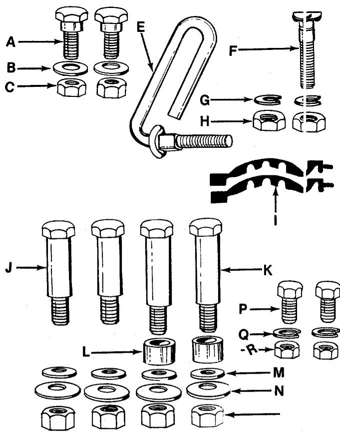
FIGURE 1.
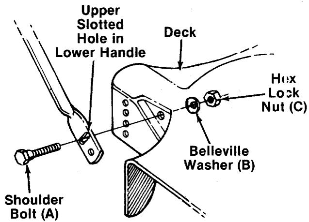
FIGURE 2.
ASSEMBLY INSTRUCTIONS
The instructions in this manual cover various models of mowers. Follow only those instructions which pertain to your unit.
CONTENTS OF HARDWARE PACK: (See figure 1) Hardware for Lower Handle Installation
A (2) Shoulder Bolts
B (2) Belleville Washers 5/16" I.D.
C (2) Hex Lock Nuts 5/16-18 Thread
Hardware for Upper Handle Installation
-E (1) Rope Guide Bolt
F (1) Curved Carriage Bolt
G (2) Lock Washers 5/16" I.D.
H (2) Hex Nuts 5/16-18 Thread
(2) Cable Ties (050 and 052)
Hardware for Installation of Wheels (if unassembled)
J (2) Axle Bolts 21/4 " Long
K (2) Axle Bolts 2-5/8" Long
L (2) Spacers
M (4) Belleville Washers 3/8'' I.D. x 7/8'' O.D.
N (4) Belleville Washers 3/8'' I.D. x 1-1/8" O.D.
O (4) Hex Nuts 3/8-16 Thread
Hardware for Installation of Chute Deflector (Models 050 and 051)
P (2) Hex Bolts 14 - 20 × 12 Long
Q (2) Lock Washers 14 I.D.
R (2) Hex Nuts 1/4 -20 Thread
- Remove lawn mower and loose parts from carton. Make certain all parts and literature have been removed from the carton before the carton is discarded.
- Extend the control cables and place on the floor. Be careful not to bend or kink control cables.
HANDLE INSTALLATION
- Line up the upper slotted hole in lower handle with the mounting hole on deck. Make certain the instruction label on the lower handle can be read from the operating position. Place shoulder bolt (A) through lower handle and deck. See figure 2. Place belleville washer (B) on the shoulder bolt, with the cupped side of the washer against the deck. Secure with hex lock nut (C).
NOTE
It may be necessary to bend the ends of the lower handle inward slightly to obtain a tight fit against the deck.
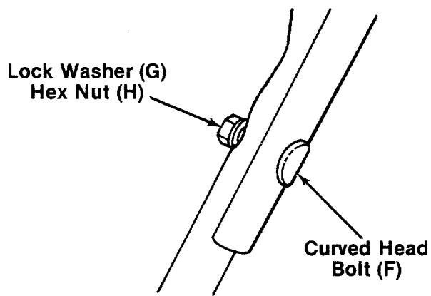
FIGURE 3.
- Place the upper handle in position over the lower handle. The control housing (on units so equipped) must be on the right hand side of the handle. Secure the left hand side of upper handle using the curved head bolt (F), lock washer (G) and hex nut (H) as shown in figure 3.

NOTE
The right hand side of the handle will be secured with the rope guide bolt. However, left handed operators may assemble the rope guide bolt to the left side of the handle for easier starting.
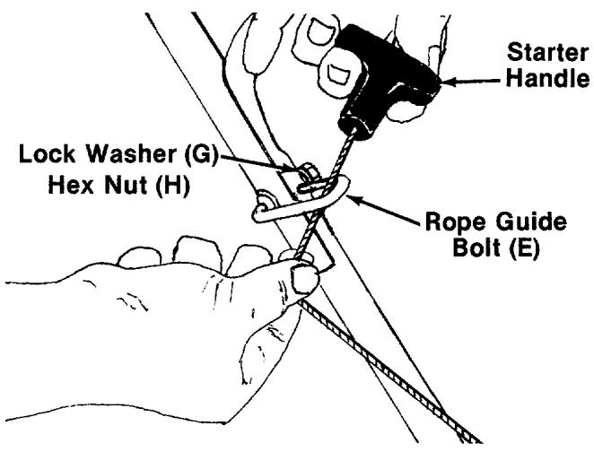
FIGURE 4.
- Insert the rope guide bolt (E) through the right hand side of upper and lower handle.
- The starter rope is wound around the starter handle. Maintain the tension on the rope as you unwind it.
- Slip the starter rope into the rope guide bolt as shown in figure 4. Secure the rope guide bolt with lock washer (G) and hex nut (H). If more slack is needed in the starter rope, disconnect and ground the spark plug wire. Depress the blade control handle and pull additional rope out from the engine.
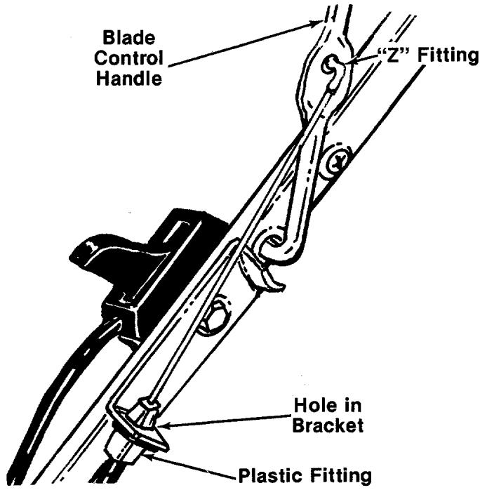
FIGURE 5.
- Route the brake cable under the lower handle. Place the end of the brake cable into the hole in the bracket as shown in figure 5. Be careful not to bend or kink the cable. Snap the plastic fitting on the end of the cable into the hole in the bracket.
Hook the "Z" end of the brake cable into the hole in the blade control handle. See figure 5.

WARNING
Brake cable must be assembled as shown for proper blade brake operation.
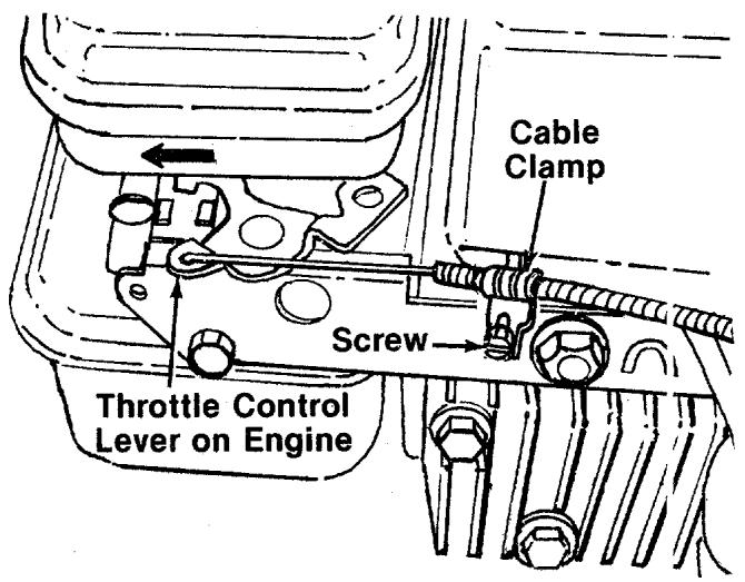
FIGURE 6.
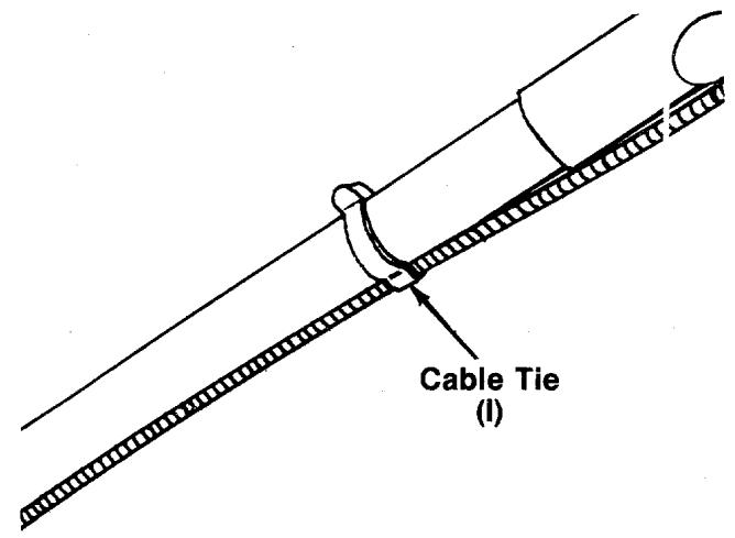
FIGURE 7.
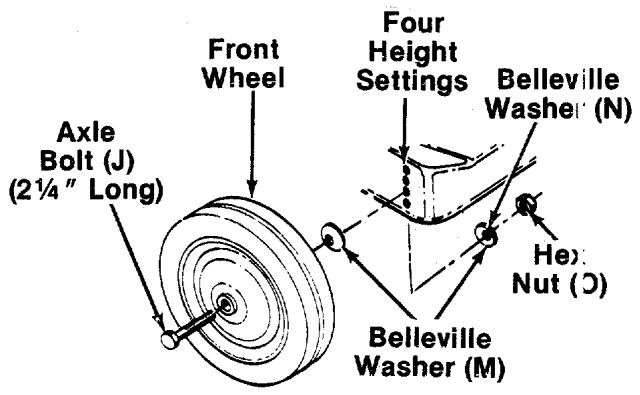
FIGURE 8.
Steps 7 through 11 are for models 050 and 052 only, which are equipped with remote throttle controls.
- Place the throttle control lever on the handle in "Fast" position.
- Push the throttle control lever on the engine to the full open position (as far toward the outside of the unit as it will go) as shown in figure 6.
- Hook the "Z" end of the throttle control cable into the hole in the control lever on the engine.
-
Remove the screw on the cable clamp shown in figure 6. Slip the control casing under the clamp. With the throttle lever on the engine still in the full open position, replace and tighten the screw to secure the throttle control cable.
-
Secure throttle control cable and brake cable to upper and lower handles with cable ties (I). See figure 7.
INSTALLATION OF WHEELS
If the wheels on your mower are not already assembled, proceed as follows.
The four holes provide four cutting heights for your mower. Use the same hole location for all four wheels when assembling. If wheels are to be assembled in the lowest cutting position (highest hole in the deck), refer to the note below.
To assemble the front wheels: (See figure 8)
- Place axle bolt (J) (214'' Long) through wheel.
- Place one belleville washer 7/8'' O.D. (M) on axle bolt, with the cupped side of washer toward the deck (away from wheel).
- Secure wheel to deck with one belleville washer 1 - 1 / 8'' O.D. (N) on the inside of the deck (cupped side against the deck) and hex nut (O).

NOTE
If the lowest cutting position (highest hole in the deck) is used, it is necessary to place the 1-1/8" washer on the outside of the deck and the 7/8" washer on the inside.
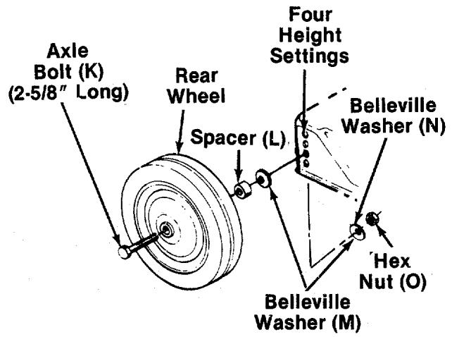
FIGURE 9.
To assemble the rear wheels: (See figure 9)
- Place axle bolt (K) (2-5/8" long) through rear wheel.
- Place spacer (L) on axle bolt, next to wheel.
- Place one belleville washer 7/8'' O.D. (M) on axle bolt, with the cupped side of washer toward the deck (away from spacer).
- Secure wheel to deck with one belleville washer 1 - 1 / 8'' O.D. (N) on the inside of the deck (cupped side against the deck) and hex nut (O).
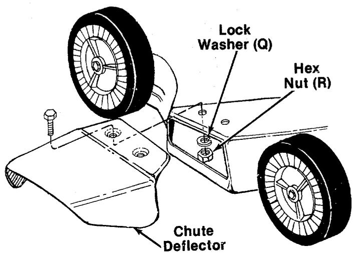
FIGURE 10.
CHUTE DEFLECTOR
Models 050 and 051:
The chute deflector provided is a safety device. Do not operate the mower unless the chute deflector has been properly installed.
Place the chute deflector in position on the deck. Secure with hex bolts (P), lock washers (Q) and -hex nuts (R). See figure 10.
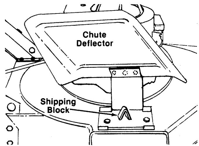
FIGURE 11.
Models 052 and 053:
The chute deflector on your mower is in an upright position. It is held in that position by a shipping block. This block is used for shipping purposes only. It must be removed and discarded before the mower is put into operation. See figure 11.
FINAL CHECK
Check all nuts and bolts for correct tightness.
CONTROLS
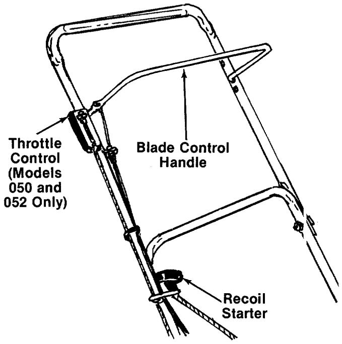
FIGURE 12.
BLADE CONTROL HANDLE
WARNING
THIS CONTROL MECHANISM IS A SAFETY DEVICE NEVER ATTEMPT TO BYPASS ITS OPERATIONS
The blade control handle is located on the upper handle of the mower. See figure 12. The blade control handle must be depressed in order to operate the unit. Release the blade control handle to stop the engine and blade.

WARNING
The blade will be rotating whenever the engine is running.
THROTTLE CONTROL (Models 050 and 052)
The throttle control is located on the right side of the upper handle. It is used to regulate the engine speed. The engine should be started with the engine in the FAST or START position.


The throttle control cannot be used to stop the engine.
RECOIL STARTER
The recoil starter handle is attached to the handle. See figure 12. Stand behind the unit in the operating position to start the unit.
OPERATION
Caution
Do Not Operate Mower Unless This Guard Or Entire Grasscatcher Is In Its Proper Place.
DANGER
KEEP HANDS and FEET AWAY

FIGURE 13.
Keep hands and feet away from the chute area on cutting deck. See figure 13.

NOTE
If the wheels on your unit were assembled at the factory, they are set in a low cutting height position for shipping purposes. For best results, raise the cutting position until it is determined which height is best for your lawn. See cutting height adjustment.
BEFORE STARTING
- Service engine with oil and gasoline as instructed in the separate engine manual packed with your unit. Read the instructions carefully.
- Attach spark plug wire to spark plug.
TO START ENGINE AND ENGAGE BLADE
- Models 050 and 052: Move the throttle control lever to FAST or START position.
Models 051 and 053: Prime engine as instructed in the separate engine manual.
- Standing behind the unit, depress the blade control handle and hold it against the upper handle as shown in figure 14.
- Grasp the recoil starter handle as shown and pull up rapidly. Return it slowly to the rope guide bolt.
- After engine starts, move throttle control lever to desired engine speed on models 050 and 052.
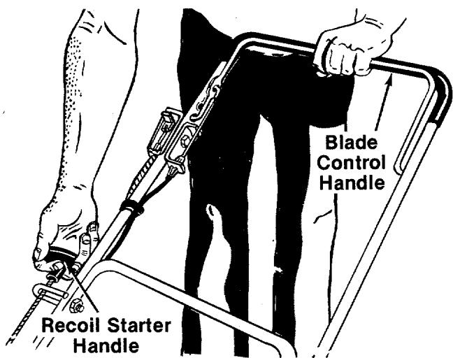
FIGURE 14.
TO STOP ENGINE AND BLADE
- Release the blade control handle to stop the engine and blade.

WARNING
The blade continues to rotate for a few seconds after the engine is shut off.
- Disconnect the spark plug wire and ground it against the engine to prevent accidental starting while equipment is unattended.
USING YOUR ROTARY MOWER
Be sure that lawn is clear of stones, sticks, wire, or other objects which could damage lawn mower or engine. Such objects could be accidentally thrown by the mower in any direction and cause serious personal injury to the operator and others.
For best results, do not cut wet grass because it tends to stick to the underside of the mower, preventing proper discharge of grass clippings, and could cause you to slip and fall. New grass, thick grass or wet grass may require a narrower cut. Blade speed should be adjusted to the condition of the lawn.
The best mowing pattern is one that allows the clippings to discharge towards the uncut part of the lawn. This permits recutting of the clippings to further pulverize them. When cutting high weeds, discharge towards cut portion, then recut at right angles to first direction.
For best results, cut off one-third or less of the total length of the grass. Lawn should be cut in the fall as long as there is growth.
This mower is designed to be operated at full throttle to give you the best cut and do the most effective job of bagging the cut grass.

IMPORTANT
If you strike a foreign object, stop the engine. Remove wire from spark plug, thoroughly inspect the mower for any damage, and repair the damage before restarting and operating the mower. Extensive vibration of the mower during operation is an indication of damage. The unit should be promptly inspected and repaired.
ADJUSTMENTS


Do not at any time make any adjustment to lawn mower without first stopping engine and disconnecting spark plug wire.
CUTTING HEIGHT ADJUSTMENT
Adjustment may be made by removing and moving axle bolts to desired position. Cutting heights will be raised as axle bolts are moved to a lower hole and lowered as axle bolts are moved to a higher hole in the deck. All axle bolts must be mounted in the same relative position. Belleville washers must be assembled so that the cupped side of the washers are against the deck. The spacers must be assembled between the rear wheels and the belleville washers. Refer to figures 8 and 9.
THROTTLE (Models 050 and 052 Only)
If adjustment becomes necessary, the throttle control wire assembly can be reset as follows:
-
Loosen, but do not remove, screw securing throttle control wire assembly at engine. See figure 6.
-
Move throttle control lever on hand e to "FAST" position.
- Move control lever on engine to full open position. Retighten screw to secure throttle control wire assembly.
CARBURETOR ADJUSTMENTS

WARNING
If any adjustments are made to the engine while the engine is running (e.g. carburetor), keep clear of all moving parts. Be careful of heated surfaces and muffler.
Minor carburetor adjustment may be required to compensate for differences in fuel, temperature, altitude and load.
Refer to the separate engine manual packed with your mower for carburetor adjustment information.
LUBRICATION

WARNING
Always stop engine and disconnect spark plug wire before cleaning, lubricating or doing any kind of work on lawn mower.
Blade Control—Lubricate the pivot points on the blade control handle and the brake cable at least once a season with light oil. See figure 15 The blade control must operate freely in both directions.
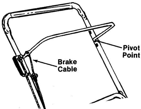
FIGURE 15.
Chute Deflector (Models 052 and 053)—The torsion spring and pivot point should be lubricated periodically with light oil to prevent any rust or binding. Deflector must work freely.
Wheels—The wheels require no lubrication. However, if the wheels are removed for any reason, lubricate the surface of the axle bolt and the inner surface of the wheel with light oil. A 4 oz. plastic bottle of light oil lubricant is available. Order part number 737-0170. Engine oil may also be used.
Engine—Follow engine manual for lubrication instructions.
Throttle (Models 050 and 052)—Periodically lubricate throttle control lever and throttle wire assembly with a few drops of light oil for ease of operation.
MAINTENANCE

NOTE
When tipping the unit, empty the fuel tank and keep engine spark plug side up.
CUTTING BLADE
A. Removal for Sharpening or Replacement

WARNING
Be sure to disconnect and ground the spark plug wire before working on the cutting blade to prevent accidental engine starting.
Remove the large bolt and lock washer which holds the blade and adapter to the engine crankshaft. Remove the blade and adapter from the crankshaft.
If the blade or blade adapter needs replacing, remove the two small bolts, lock washers and nuts which hold the blade to the adapter.

CAUTION
Periodically inspect the blade adapter for cracks, especially if you strike a foreign object. Replace when necessary.
B. Sharpening
Remove the cutting blade by following the directions of the preceding section.
When sharpening the blade, follow the original angle of grind as a guide. It is extremely important
that each cutting edge receives an equal amount of grinding to prevent an unbalanced blade. An unbalanced blade will cause excessive vibration when rotating at high speeds, may cause damage to the mower and could break, causing personal injury.
It is recommended that the blade always be removed from the adapter for the best test of balance. The blade can be tested by balancing it on a round shaft screwdriver. Remove metal from the heavy side until it balances evenly.
C. Reassembly
Before reassembling the blade and the blade adapter to the unit, lubricate the engine crankshaft and the inner surface of the blade adapter with light oil. Lubricating the bolt holes, bolts and inner surface of the nuts with light oil is also recommended. A 4 oz. plastic bottle of light oil lubricant is available. Order part number 737-0170. Engine oil may also be used.
When replacing the blade, be sure to install the blade with the side of the blade marked "Bottom" (or with part number) facing the ground when the mower is in the operating position.
Blade Mounting Torque
3/8" Dia. Bolt 375 in. lb. min., 450 in. lb. max.
5/16" Dia. Bolt 150 in. lb. min., 250 in. lb. max.
To insure safe operation of your unit, all nuts and bolts must be checked periodically for correct tightness.
DECK
The underside of mower deck should be cleaned after each period of use as grass clippings, leaves, dirt and other matter will accumulate. This accumulation of grass clippings, etc., is undesirable as it will invite rust and corrosion and may cause an uneven discharge of grass clippings at the next cutting.
The deck may be cleaned by tilting the mower forward or on its side and scraping clean with a suitable tool or by washing with a stream of water from a garden hose.

NOTE
Do not direct the stream of water at a hot engine as damage to the engine may result.
ENGINE
Refer to the separate engine manual for engine maintenance instructions.
AIR CLEANER
Service air cleaner every 25 hours under normal conditions. Clean every few hours under extremely dusty conditions. Poor engine performance and flooding usually indicates that the air cleaner should be serviced.
To service the air cleaner, refer to the separate engine manual packed with your unit.
SPARK PLUG
The spark plug should be cleaned and the gap reset once a season. Spark plug replacement is recommended at the start of each mowing season; check engine manual for correct plug type and gap specifications.
OFF-SEASON STORAGE
The following steps should be taken to prepare lawn mower for storage.
- Clean and lubricate mower thoroughly as described in the lubrication instructions.
- Refer to engine manual for correct engine storage instructions.
- Coat mower's cutting blade with chassis grease to prevent rusting.
- Store mower in a dry, clean area.

NOTE
When storing any type of power equipment in an unventilated or metal storage shed, care should be taken to rust-proof the equipment. Using a light oil or silicone, coat the equipment, especially cables and all moving parts.

NOTE
The use of any accessory on this Rotary Mower other than those manufactured by the mower manufacturer is not recommended.
Grass catcher Model 065 is available as optional equipment for the Models 052 and 053. No grass catcher is available for Models 050 and 051.

WARNING
- DO NOT operate the mover without the entire grass catcher or chute deflector in place.
- DO NOT operate the mover without the protective shield on the rear of the deck in place.

NOTE
Under normal usage bag material is subject to wear and should be checked periodically. Be sure any replacement bag complies with the mower manufacturer's recommendations.
For replacement bags, use only factory authorized replacement bag No. 764-0217.
Trouble Shooting Chart
| Problem | Cause | Remedy |
| 1 Engine fails to start | A Blade control handle disengagedB Check fuel tank for gasC Spark plug lead wire disconnected.D Throttle control lever not in the starting positionE Faulty spark plugF Carburetor improperly adjusted, engine floodedG Old stale gasolineH Engine brake engaged | A Engage blade control handle.B Fill tank if empty.C Connect lead wire.D Move throttle lever to start position.E Spark should jump gap between control electrode and side electrode. If spark does not jump, replace the spark plug.F Remove spark plug, dry the plug, crank engine with plug removed, and throttle in off position. Replace spark plug and lead wire and resume starting procedures.G Drain and refill with fresh gasoline.H Follow starting procedure. |
| 2 Hard starting or loss of power | A Spark plug wire looseB Carburetor improperly adjustedC Dirty air cleaner | A Connect and tighten spark plug wire.B Adjust carburetor. See separate engine manual.C Clean air cleaner as described in separate engine manual. |
| 3 Operation erratic | A Dirt in gas tankB Dirty air cleanerC Water in fuel supplyD Vent in gas cap pluggedE Carburetor improperly adjusted | A Remove the dirt and fill tank with fresh gas.B Clean air cleaner as described in separate engine manual.C Drain contaminated fuel and fill tank with fresh gas.D Clear vent or replace gas cap.E Adjust carburetor. See separate engine manual. |
| 4 Occasional skip (hesitates) at high speed | A Carburetor idle speed too slowB Spark plug gap too closeC Carburetor idle mixture adjustment improperly set | A Adjust carburetor. See separate engine manual.B Adjust to .030".C Adjust carburetor. See separate engine manual. |
| 5 Idles poorly | A Spark plug fouled, faulty, or gap too wideB Carburetor improperly adjustedC Dirty air cleaner | A Reset gap to .030" or replace spark plug.B Adjust carburetor. See separate engine manual.C Clean air cleaner as described in separate engine manual. |
| 6 Engine overheats | A Carburetor not adjusted properlyB Air flow restrictedC Engine oil level low | A Adjust carburetor. See separate engine manual.B Remove blower housing and clean as described in separate engine manual.C Fill crankcase with the proper oil. |
| 7 Excessive vibration | A Cutting blade loose or unbalancedB Bent cutting blade | A Tighten blade and adapter. Balance blade.B Replace blade. |
Note: For repairs beyond the minor adjustments listed above, contact your local authorized service dealer.
Models 050, 051, 052 and 053
Meets CPSC Blade Safety Requirements
Lot/Model
Mfg. Date
NOTE
This instruction manual covers various models and all specifications shown do not necessarily apply to your model. Specifications subject to change without notice or obligation.
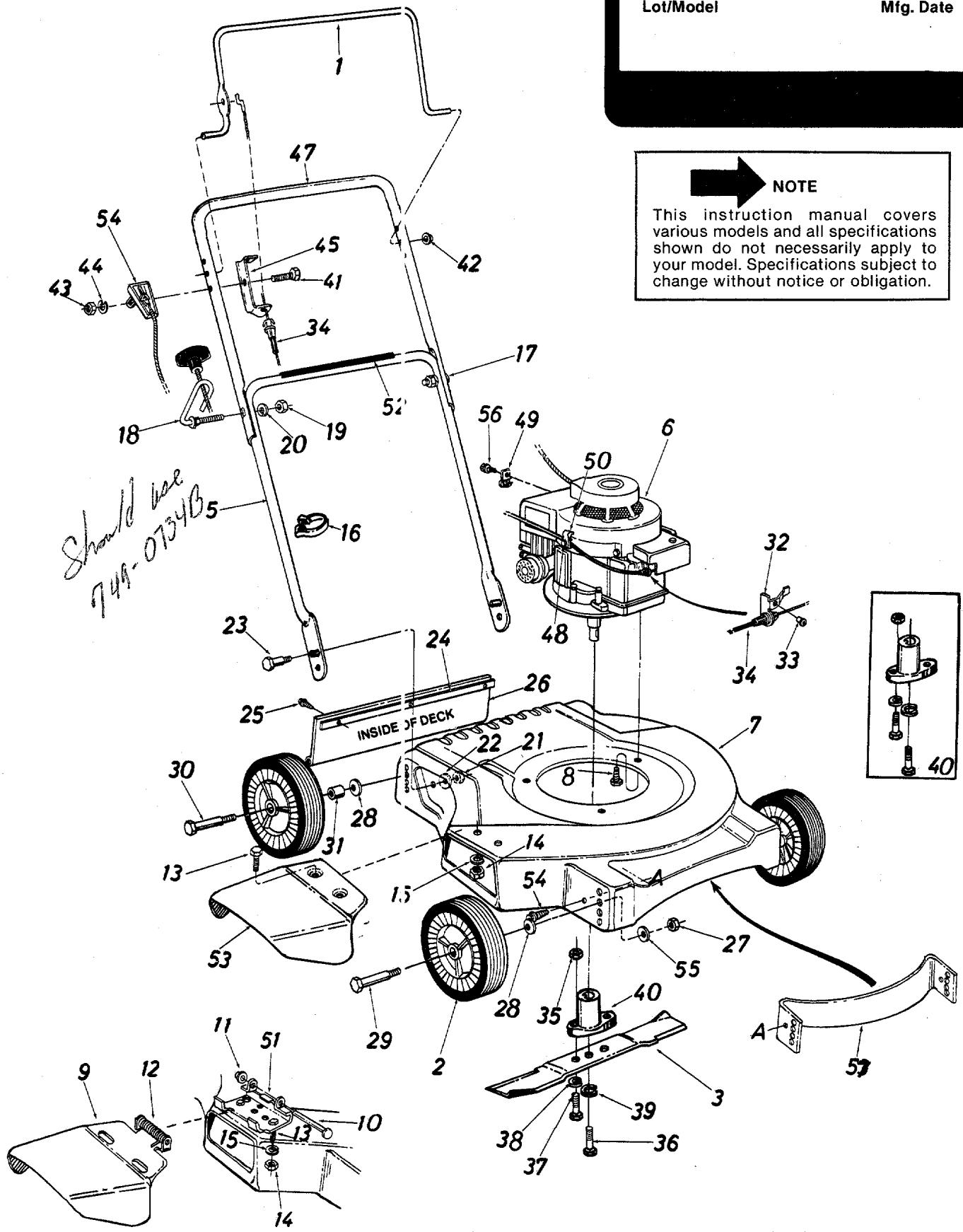
Models 050, 051, 052 and 053
PARTS LIST FOR MODELS 050, 051, 052 and 053 ROTARY MOWERS
| REF.NO. | PARTNO. | COLORCODE | DESCRIPTION | NEWPART | REF.NO. | PARTNO. | COLORCODE | DESCRIPTION | NEWPART |
| 1 | 747-0500 | Control Handle | N | 30 | 738-0509 | Shld. Bolt (Rear Axle) | |||
| 2 | ** | Plastic Wheel Ass'y. | 31 | 750-0515 | Spacer | ||||
| 3 | 742-0123 | 20" Blade | 32 | 14924 | Cable Bracket (050 & 052) | ||||
| 5 | 749-0373 | 0734 | Lower Handle (Chrome) | 33 | 728-0171 | Pop Rivet .156" Dia. x .379(050 & 052) | |||
| 6 | 749-0372 | Lower Handle (Painted) | Control Cable-43.0" Lg. | N | |||||
| 7 | 16202 | -462 | Engine | N | 34 | 746-0551 | Hex Nut 5/16-24 Thd.* | ||
| 8 | 16393 | -462 | 20" Deck | N | 35 | 712-0123 | Hex Bolt 3/8-24 x 1.00" Lg.(Grade 5) | ||
| 9 | 710-0654 | 20" Deck (Used w/Ref.No. 57) | N | 36 | 710-0152 | Hex Bolt 5/16-24 x 1.00" Lg.(Grade 5) | |||
| 10 | 711-0555 | Hex Wash. Hd. TT-Tap Scr.3/8-16 x 1.00" Lg. | 37 | 710-0888 | Hex Bolt 5/16-24 x 1.00" Lg.(Grade 5) | ||||
| 11 | 726-0106 | Chute Deflector Ass'.(052 & 053) | 38 | 736-0119 | L-Wash. 5/16" I.D.* | ||||
| 12 | 732-0253 | Pivot Pin (052 & 053) | 39 | 736-0217 | L-Wash. 3/8" I.D. HeavyDuty | ||||
| 13 | 710-0289 | Cap Speed Nut 1/4" Rod(052 & 053) | 40 | 753-0343 | Blade Adapter Kit | ||||
| 14 | 712-0287 | Torsion Spring (052 & 053) | 41 | 710-0559 | Hex Bolt 1/4-28 x 1.75" Lg.* | ||||
| 15 | 736-0329 | Hex Bolt 1/4-20 x .50" Lg.* | 43 | 712-0138 | Hex Nut 1/4-28 Thd. | ||||
| 16 | 726-0192 | Hex Nut 1/4-20 Thd.* | 44 | 736-0175 | L-Wash. 1/4" I.D. | ||||
| 17 | 710-0671 | Cable Tie | 45 | 16201 | Cable Mounting Brkt. | N | |||
| 18 | 710-0842 | Curved Carriage Bolt5/16-18 x 1.38" Lg. | 47 | 749-0536 | Upper Handle (Chrome)Lg. (050 & 052) | ||||
| 19 | 712-0267 | Rope Guide Bolt | 48 | 710-0429 | Casing Clamp (050 & 052) | ||||
| 20 | 736-0119 | Hex Nut 5/16-18 Thd.* | 50 | 12894 | Casing Clamp (050 & 052) | ||||
| 21 | 712-0429 | L-Wash. 5/16" I.D.* | 51 | 11130 | Hinge Plate (052 & 053) | ||||
| 22 | 736-0242 | Hex Ins. L-Nut 5/16-18 Thd.Bell-Wash. .345" I.D. x .88"O.D. | 52 | 777-3455 | Instruction Label-HandleChute Deflector (050 & 051) | N | |||
| 23 | 738-0296 | Shld. Bolt .437" Dia. x .268"Lg. | 53 | 16203 | Throttle Control Ass'y. -Comp. (050 & 052) | N | |||
| 24 | 14836 | Retainer Strip | 54 | 746-0558 | Bell-Wash. .39" I.D. x 1.13"O.D. | ||||
| 25 | 710-0776 | Hex Wash. Hd. Self-Tap Scr.1/4" x .62" Lg. | 55 | 736-0331 | Hex AB-Tap Scr. #8 x .38"Lg. (050 & 052) | ||||
| 26 | 731-0670 | Rear Flap Ass'y.Hex Nut 3/8-16 Thd.* | 56 | 710-0227 | Baffle (Optional) | ||||
| 27 | 712-0798 | Bell-Wash. .400" I.D. x .88"O.D. | 57 | 16328 | Hex B-Tap Screw 1/4 x .38"Lg. (Optional) | N | |||
| 28 | 736-0105 | 58 | 710-0352 | ||||||
| 29 | 738-0213 | Shld. Bolt (Front Axle) |
*For faster service obtain standard nuts, bolts, and washers locally. If these items cannot be obtained locally, order by part number and size as shown on parts list.
**Wheel Assembly
| 7"8" | 734-0840734-0841 | 734-1176734-1177 |
(462—Red Flake)
When ordering parts if color or finish is important, use the appropriate color code shown above. (e.g. Red Flame Finish—11402 (462).)
NOTE: The engine is not under warranty by the mower manufacturer...If repairs or service is needed on the engine, please contact your nearest authorized engine service outlet. Check the "Yellow Pages" of your telephone book under "Engines-Gasoline." Find It Fast In The Yellow Pages
PARTS INFORMATION
POWER EQUIPMENT PARTS AND SERVICE
Parts and service are available through the authorized service firms listed below. All orders should specify the model numt er of your unit, part numbers, description of parts and the quant ty of each part required.
BRIGGS AND STRATTON, TECUMSEH AND PEERLESS PARTS AND SERVICE
Briggs & Stratton, Tecumseh and Peerless parts and service should be handled by your nearest authorized engine service firm. Check the yellow pages of your telephone directory under the listing Engines—Gasoline, Briggs & Stratton or Tecumseh Lauson.
NOTE: If any parts are found to be missing or defective upon assembly of this unit, write to advise the factory so that immediate replacement can be made.
| ALABAMA | BIRMINGHAM |
| Auto Electric & Carburetor Co. | 2625 4th Ave. S. .35233 |
| ARKANSAS | NORTH LITTLE ROCK |
| Sutton's Lawn Mower Shop | 5301 Roundtop Drive Box 368, Rt. 4 .2117 |
| CALIFORNIA | PORTERVILLE |
| Billious | 75 North D Street .93257 |
| COLORADO | DENVER |
| Spitzer Industrial Products Co. | 6601 N. Washington St. .80229 |
| FLORIDA | JACKSONVILLE |
| Radco Distributors | 4909 Victor St. Box 5459 .2207 |
| HIALEAH | |
| Small Eng. Dist. | 7995 W. 26th Court .3016 |
| GEORGIA | EAST POINT |
| East Point Cycle & Key Inc. | 2834 Church St. .10344 |
| ILLINOIS | LYONS |
| Keen Edge Co. | 8615 Ogden Ave. .0534 |
| INDIANA | ELKHART |
| Parts & Sales Inc. | 2101 Industrial Pkwy. .6516 |
| IOWA | DUBUQUE |
| Power Lawn & Garden Equip. | 2551 J.F. Kennedy .2001 |
| LOUISIANA | NEW ORLEANS |
| Suhren Engine Co. | 8330 Earhart Blvd. .70118 |
| MARYLAND | TAKOMA PARK |
| Center Supply Co. | 6867 New Hampshire Ave. .20912 |
| MASSACHUSETTS | SPRINGFIELD |
| Morton B. Collins Co. | 300 Birnie Ave. .01107 |
| MICHIGAN | LANSING |
| Lorenz Service Co. | 2500 S. Pennsylvania .48910 |
| MOUNT CLEMENS | |
| Power Equipment Dist. | 340 Hubbard .48043 |
| MINNESOTA | HOPKINS |
| Hance Distributing Inc. | 420 Excelsior Ave. W. .55343 |
| MISSISSIPPI | BILOXI |
| Biloxi Sales & Service, Inc. | 506 Caillavet St. .9533 |
| MISSOURI | KANSAS CITY |
| Automotive Equip. Service | 3117 Holmes St. .4109 |
| ST. JOSEPH | |
| Ross-Frazer Supply Co. | 8th and Monterey .4503 |
| ST. LOUIS | |
| Henzler, Inc. | 2015 Lemay Ferry Rd. .3125 |
| NEW JERSEY | BELLMAWR |
| Lawnmower Parts Inc. | 717 Creek Rd. .8030 |
| NEW MEXICO | ALBUQUERQUE |
| Spitzer Eng. & Parts Co. | 1023 Third Ave. N.W. .87103 |
| NEW YORK | CARTHAGE |
| Gamble Dist., Inc. | West End Ave. .13619 |
| OHIO | CARROLL | |
| Stebe's Mid-State Mower Supply | Box 366, 71 High St. | 43112 |
| CLEVELAND | ||
| Bleckrie, Inc. | 7900 Lorain Ave. | 44102 |
| WADSWORTH | ||
| National Central | 687 Seville Rd. | 44281 |
| YOUNGSTOWN | ||
| Burton Supply Co. | 1301 Logan Ave. | |
| Box 929 | 44501 | |
| OKLAHOMA | MUSKOGEE | |
| Victory Motors, Inc. | 605 S. Cherokee | 74401 |
| OREGON | PORTLAND | |
| Kenton Supply Co. | 8216 N. Denver Ave. | 97217 |
| PENNSYLVANIA | HARRISBURG | |
| EECO Inc. | 4021 N. 6th St. | 17110 |
| PHILADELPHIA | ||
| Thompson Rubber Co. | 5222-24 N. Fifth St. | 19120 |
| PITTSBURGH | ||
| Bluemont Co. | 11125 Frankstown Rd. | 15235 |
| PUNXSUTAWNEY | ||
| Frank Roberts & Sons | R.D. 2 | 15767 |
| SCRANTON | ||
| Scranton Auto Ignition Co. | 1133-35 Wyoming Ave. | 18509 |
| TENNESSEE | KNOXVILLE | |
| Master Repair Service | 2000 Western Ave. | 37921 |
| MEMPHIS | ||
| American Sales & Service, Inc. | 3035-43 Bellbrook | 38116 |
| TEXAS | DALLAS | |
| Marr Brothers, Inc. | 423 E. Jefferson | 75203 |
| FORT WORTH | ||
| Woodson Sales Corp. | 6733 Baker Blvd. | |
| Hwy. 10 | 76118 | |
| HOUSTON | ||
| Bullard Supply Co. | 2409 Commerce St. | 77003 |
| SAN ANTONIO | ||
| Engine House Inc. | 8610 Botts Lane | |
| P.O. Box 17867 | 78217 | |
| UTAH | BOUNTFUL | |
| Powered Products | 485 N 500 W. | 84010 |
| VIRGINIA | ASHLAND | |
| RBI Corp. | 101 Cedar Ridge Dr. | 23005 |
| WASHINGTON | SEATTLE | |
| Equip. Northwest | 1410 14th Ave. | 98122 |
| WISCONSIN | CHILTON | |
| Horst Dist. Inc. | 444 N. Madison St. | 53014 |
| NORTH CAROLINA | GOLDSBORO | |
| Smith Hardware Co. | 515 N. George St. | 27530 |
| GREENSBORO | ||
| Dixie Sales Company | 335 N. Green | 27402 |
WARRANTY PARTS AND SERVICE POLICY
(0484)
The purpose of warranty is to protect the customer from defects in workmanship and materials, defects which are NOT detected at the time of manufacture. It does not provide for the unlimited and unrestricted replacement of parts. Use and maintenance are the responsibility of the customer. The manufacturer cannot assume responsibility for conditions over which it has no control. Simply put, if it's the manufacturer's fault, it's the manufacturer's responsibility; if it's the customer's fault, it's the customer's responsibility.
CLAIMS AGAINST THE MANUFACTURER'S WARRANTY INCLUDES:
- Replacement of Missing Parts on new equipment.
- Replacement of Defective Parts within the warranty period.
- Repair of Defects within the warranty period.
All claims MUST be substantiated with the following information:
- Model Number of unit involved.
- Date unit was purchased or first put into service.
- Date of failure.
- Nature of failure.