TRAK-RITE PPL 40+ - Pneus DUNLOP - Notice d'utilisation et mode d'emploi gratuit
Retrouvez gratuitement la notice de l'appareil TRAK-RITE PPL 40+ DUNLOP au format PDF.
| Type de produit | Jauge de parallélisme laser |
| Marque | DUNLOP |
| Modèle | TRAK-RITE PPL 40+ |
| Utilisation | Mesure du pincement et de l'ouverture des roues |
| Compatibilité jantes | 8 à 24 pouces de diamètre |
| Précision | Graduation par 10 minutes d'angle |
| Portée véhicules | 2, 3 ou 4 essieux (voitures, camions) |
| Fonction calculatrice | Conversion de l'angle en mesure linéaire (mm ou pouce) |
| Hauteurs de barres de contact | 5 positions réglables |
| Orientation des barres | Gauche/droite et bras long/court réversibles |
| Alimentation | Piles (non fournies) |
| Sécurité | Ne pas diriger le faisceau laser vers les yeux |
| Entretien | Nettoyer avec un chiffon doux et sec |
| Accessoires optionnels | Miroir supplémentaire PPL 42 pour essieux jumelés |
| Notice fournie | Oui, en anglais |
| Poids approximatif | 1,5 kg |
FOIRE AUX QUESTIONS - TRAK-RITE PPL 40+ DUNLOP
Questions des utilisateurs sur TRAK-RITE PPL 40+ DUNLOP
0 question sur cet appareil. Repondez a celles que vous connaissez ou posez la votre.
Poser une nouvelle question sur cet appareil
Téléchargez la notice de votre Pneus au format PDF gratuitement ! Retrouvez votre notice TRAK-RITE PPL 40+ - DUNLOP et reprennez votre appareil électronique en main. Sur cette page sont publiés tous les documents nécessaires à l'utilisation de votre appareil TRAK-RITE PPL 40+ de la marque DUNLOP.
MODE D'EMPLOI TRAK-RITE PPL 40+ DUNLOP
Trak-Rite PPL 40+ Laser Wheel Alignment Gauge
INSTRUCTIONS FOR USE
The Laser Alignment Gauge precisely measures the angle between pairs of wheels on a vehicle to give toe-in and toe-out figures. Before using, read these instructions carefully.
Never direct the Laser Beam at a person. If the beam is obstructed by a person during use, release the contact switch immediately.
Assembly Instructions
Assemble the gauge, ensuring that the mirror unit (B) and the laser/target unit (D) are on the correct side (see Figure 1).
There are five different height positions for the contact bars to suit the radius of the tyre and wheel assembly being checked. Choose a height as near to
the hub centre as possible and see that all the bars are at the same height. Each contact bar may be fitted either to the left or right of its respective support arm and may be reversed to use the long or short contact arm. This is to allow the gauge to handle all tyres on 8'' to 24'' diameter rims and to allow close contact when required e.g. when in use on a lift.
Calibration Check
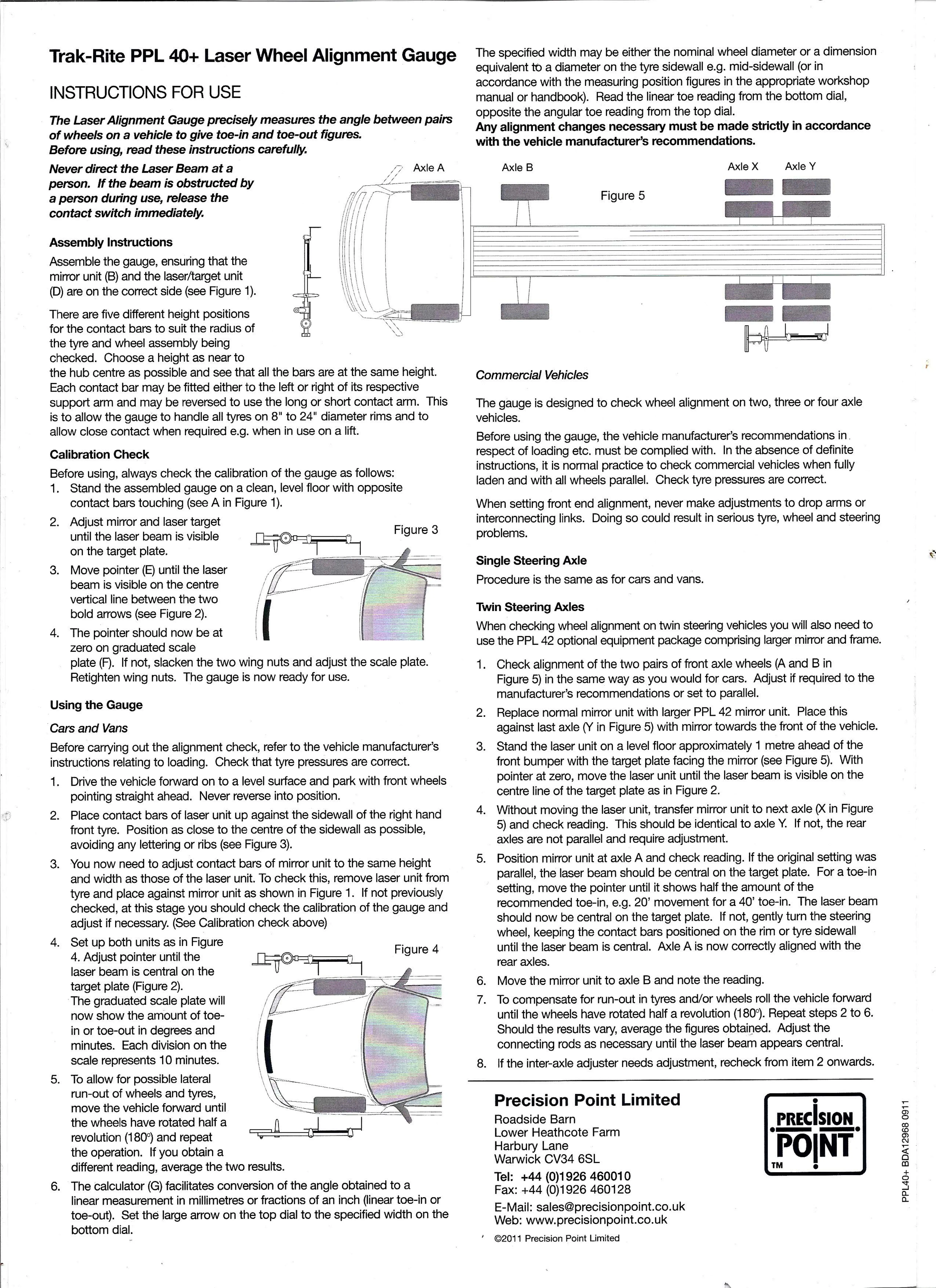
Before using, always check the calibration of the gauge as follows:
- Stand the assembled gauge on a clean, level floor with opposite contact bars touching (see A in Figure 1).
- Adjust mirror and laser target until the laser beam is visible on the target plate.
- Move pointer (E) until the laser beam is visible on the centre vertical line between the two bold arrows (see Figure 2).
- The pointer should now be at zero on graduated scale plate (F). If not, slacken the two Retighten wing nuts. The gau
Using the Gauge
Cars and Vans
Before carrying out the alignment check, refer to the vehicle manufacturer's instructions relating to loading. Check that tyre pressures are correct.
- Drive the vehicle forward on to a level surface and park with front wheels pointing straight ahead. Never reverse into position.
- Place contact bars of laser unit up against the sidewall of the right hand front tyre. Position as close to the centre of the sidewall as possible, avoiding any lettering or ribs (see Figure 3).
- You now need to adjust contact bars of mirror unit to the same height and width as those of the laser unit. To check this, remove laser unit from tyre and place against mirror unit as shown in Figure 1. If not previously checked, at this stage you should check the calibration of the gauge and adjust if necessary. (See Calibration check above)
- Set up both units as in Figure 4. Adjust pointer until the laser beam is central on the target plate (Figure 2). The graduated scale plate will now show the amount of toe-in or toe-out in degrees and minutes. Each division on the scale represents 10 minutes.
- To allow for possible lateral run-out of wheels and tyres, move the vehicle forward until the wheels have rotated half a revolution (180^) and repeat the operation. If you obtain a different reading, average the t
- The calculator (G) facilitates conversion of the angle obtained to a linear measurement in millimetres or fractions of an inch (linear toe-in or toe-out). Set the large arrow on the top dial to the specified width on the bottom dial.
Commercial Vehicles
The gauge is designed to check wheel alignment on two, three or four axle vehicles.
Before using the gauge, the vehicle manufacturer's recommendations in respect of loading etc. must be complied with. In the absence of definite instructions, it is normal practice to check commercial vehicles when fully laden and with all wheels parallel. Check tyre pressures are correct.
When setting front end alignment, never make adjustments to drop arms or interconnecting links. Doing so could result in serious tyre, wheel and steering problems.
Single Steering Axle
Procedure is the same as for cars and vans.
Twin Steering Axles
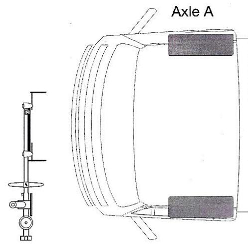
When checking wheel alignment on twin steering vehicles you will also need to use the PPL 42 optional equipment package comprising larger mirror and frame.
- Check alignment of the two pairs of front axle wheels (A and B in Figure 5) in the same way as you would for cars. Adjust if required to the manufacturer's recommendations or set to parallel.
- Replace normal mirror unit with larger PPL 42 mirror unit. Place this against last axle (Y in Figure 5) with mirror towards the front of the vehicle.
- Stand the laser unit on a level floor approximately 1 metre ahead of the front bumper with the target plate facing the mirror (see Figure 5). With pointer at zero, move the laser unit until the laser beam is visible on the centre line of the target plate as in Figure 2.
- Without moving the laser unit, transfer mirror unit to next axle (X in Figure 5) and check reading. This should be identical to axle Y. If not, the rear axles are not parallel and require adjustment.
- Position mirror unit at axle A and check reading. If the original setting was parallel, the laser beam should be central on the target plate. For a toe-in setting, move the pointer until it shows half the amount of the recommended toe-in, e.g. 20^ movement for a 40^ toe-in. The laser beam should now be central on the target plate. If not, gently turn the steering wheel, keeping the contact bars positioned on the rim or tyre sidewall until the laser beam is central. Axle A is now correctly aligned with the rear axles.
- Move the mirror unit to axle B and note the reading.
- To compensate for run-out in tyres and/or wheels roll the vehicle forward until the wheels have rotated half a revolution (180^) . Repeat steps 2 to 6. Should the results vary, average the figures obtained. Adjust the connecting rods as necessary until the laser beam appears central.
- If the inter-axle adjuster needs adjustment, recheck from item 2 onwards.
Precision Point Limited
Roadside Barn
Lower Heathcote Farm
Harbury Lane
Warwick CV34 6SL
Tel: +44 (0)1926 460010
Fax: +44 (0)1926 460128
E-Mail: sales@precisionpoint.co.uk
Web: www.precisionpoint.co.uk
©2011 Precision Point Limited