
BLEEDKIT-45-14576B - Freinage automobile HAYES DISC BRAKES - Notice d'utilisation et mode d'emploi gratuit
Retrouvez gratuitement la notice de l'appareil BLEEDKIT-45-14576B HAYES DISC BRAKES au format PDF.

| Type de produit | Kit de purge pour freins à disque HAYES |
| Compatibilité | Freins à disque HAYES |
| Utilisation | Permet de purger le système hydraulique des freins à disque pour un fonctionnement optimal |
| Composants inclus | Seringue, tuyaux, adaptateurs, liquide de frein |
| Maintenance et réparation | Recommandé de purger les freins tous les 6 mois ou selon l'utilisation |
| Sécurité | Utiliser des gants et des lunettes de protection lors de la manipulation du liquide de frein |
| Informations générales | Vérifier la compatibilité avec votre modèle de frein avant l'achat |
FOIRE AUX QUESTIONS - BLEEDKIT-45-14576B HAYES DISC BRAKES
Questions des utilisateurs sur BLEEDKIT-45-14576B HAYES DISC BRAKES
0 question sur cet appareil. Repondez a celles que vous connaissez ou posez la votre.
Poser une nouvelle question sur cet appareil
Téléchargez la notice de votre Freinage automobile au format PDF gratuitement ! Retrouvez votre notice BLEEDKIT-45-14576B - HAYES DISC BRAKES et reprennez votre appareil électronique en main. Sur cette page sont publiés tous les documents nécessaires à l'utilisation de votre appareil BLEEDKIT-45-14576B de la marque HAYES DISC BRAKES.
MODE D'EMPLOI BLEEDKIT-45-14576B HAYES DISC BRAKES
A. Bleed Kit Assembly :
- Screw the cap onto the end of the bottle.
- Cut a 2" section of hose.
- Push the short section of hose over the cap until it slides past the ridge on the cap.
- Push the long section of hose into the master cylinder bleed fitting
Note : There are two fittings with the kit. The clear, cone shaped fitting is to be used with the HFX Mag and HFX Mag Plus. The silver aluminum fitting is to be used with the HFX- 9.
B. Bleeding the System
Air entrapped in the hydraulic system of the disc brakes can decrease performance of the system and should be removed by "bleeding" the system and replenishing the system with new brake fluid. The system is filled by pumping fluid from the lowest point (at the caliper), through the system, to the highest point, the bleeder on the master cylinder.
Note: The bleed instructions include steps for the HFX Mag and HFX-9 brake systems. Read them carefully, since instructions vary for the type of brake system you have.
Caution: Use only new DOT 4 or DOT 3 brake fluid from a closed, sealed container. Use of any other fluid can cause the rubber parts to degrade and cause the brake to fail.
Caution: DOT 4 or DOT 3 brake fluid will strip paint. Use extreme caution to avoid getting DOT 4 or DOT 3 brake fluid on paint. If DOT 4 or DOT 3 brake fluid comes in contact with paint, wipe it off immediately and rinse with isopropyl alcohol.
Warning: If you get any brake fluid on the brake pads, discard them and replace with new pads. If you get any brake fluid on the disc, clean it thoroughly with isopropyl alcohol.
Warning: DOT 4 or DOT 3 brake fluid can be an irritant when it comes into contact with human tissue. For skin contact, brake fluid should be washed off in flowing water. For eye contact, the eye area should be irrigated with flowing water immediately and continuously for 15 minutes. Consult with medical personnel. If effects occur from inhaling brake fluid fumes, more than one area with fresh air. Consult a physician. If brake fluid is ingested, induce vomiting and consult medical personnel. Used brake fluid should be disposed of according to local laws.
- Remove the wheel.
- Remove the brake pads so that any spilled fluid does not contaminate the pads. Using the tab in the center of the pad backing plate, pull each pad toward the center of the caliper and out. There is a spring that holds the pad in place. That spring snaps on to the post at the center of the piston.
- Push the caliper pistons all the way into their bores using the box end of a 10mm end wrench.
Caution: Don't push on the post in the center of the piston because that will bend the post. Walk the piston back and forth until the piston is all the way back in the bore. Do the same thing on
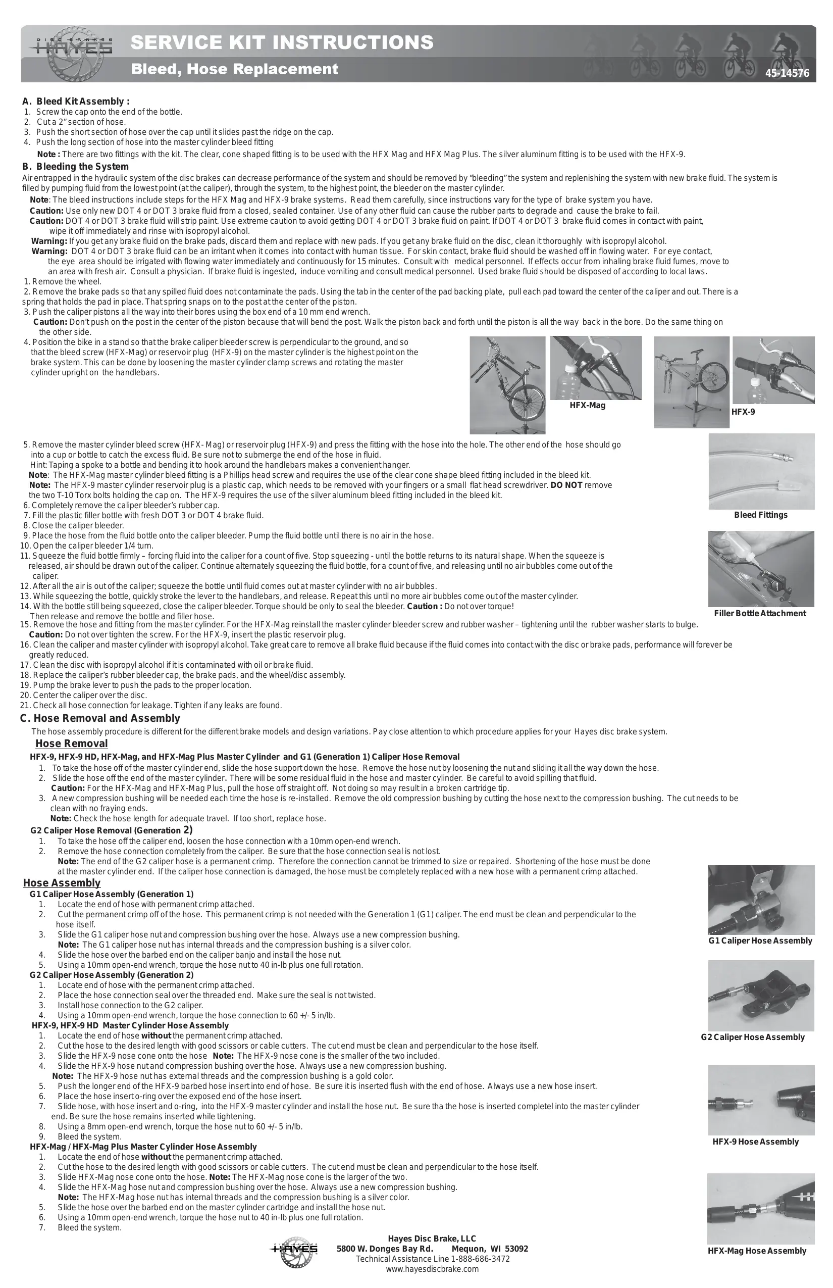
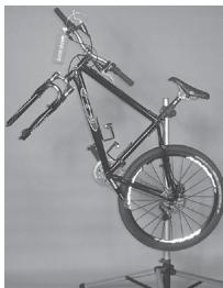
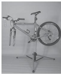
- Position the bike in a stand so that the brake caliper bleeder screw is perpendicular to the ground, and so that the bleed screw (HFX-Mag) or reservoir plug (HFX-9) on the master cylinder is the highest point on the brake system. This can be done by loosening the master cylinder clamp screws and rotating the master cylinder upright on the handlebars.

HFX-Mag
HFX-9
- Remove the master cylinder bleed screw (HFX- Mag) or reservoir plug (HFX-9) and press the fitting with the hose into the hole. The other end of the hose should go into a cup or bottle to catch the excess fluid. Be sure not to submerge the end of the hose in fluid.
Hint: Taping a spoke to a bottle and bending it to hook around the handlebars makes a convenient hanger.
Note: The HFX-Mag master cylinder bleed fitting is a Phillips head screw and requires the use of the clear cone shape bleed fitting included in the bleed kit.
Note: The HFX-9 master cylinder reservoir plug is a plastic cap, which needs to be removed with your fingers or a small flat head screwdriver. DO NOT remove the two T-10 Torx bolts holding the cap on. The HFX-9 requires the use of the silver aluminum bleed fitting included in the bleed kit. - Completely remove the caliper bleeder's rubber cap.
- Fill the plastic filler bottle with fresh DOT 3 or DOT 4 brake fluid.
- Close the caliper bleeder.
- Place the hose from the fluid bottle onto the caliper bleeder. Pump the fluid bottle until there is no air in the hose.
- Open the caliper bleeder 1/4 turn.
- Squeeze the fluid bottle firmly – forcing fluid into the caliper for a count of five. Stop squeezing - until the bottle returns to its natural shape. When the squeeze is released, air should be drawn out of the caliper. Continue alternately squeezing the fluid bottle, for a count of five, and releasing until no air bubbles come out of the caliper.
- After all the air is out of the caliper; squeeze the bottle until fluid comes out at master cylinder with no air bubbles.
- While squeezing the bottle, quickly stroke the lever to the handlebars, and release. Repeat this until no more air bubbles come out of the master cylinder.
- With the bottle still being squeezed, close the caliper bleeder. Torque should be only to seal the bleeder. Caution : Do not over torque!
Then release and remove the bottle and filler hose. - Remove the hose and fitting from the master cylinder. For the HFX-Mag reinstall the master cylinder bleeder screw and rubber washer – tightening until the rubber washer starts to bulge. Caution: Do not over tighten the screw. For the HFX-9, insert the plastic reservoir plug.
- Clean the caliper and master cylinder with isopropyl alcohol. Take great care to remove all brake fluid because if the fluid comes into contact with the disc or brake pads, performance will forever be greatly reduced.
- Clean the disc with isopropyl alcohol if it is contaminated with oil or brake fluid.
- Replace the caliper's rubber bleeder cap, the brake pads, and the wheel/disc assembly.
- Pump the brake lever to push the pads to the proper location.
- Center the caliper over the disc.
- Check all hose connection for leakage. Tighten if any leaks are found.
C. Hose Removal and Assembly
The hose assembly procedure is different for the different brake models and design variations. Pay close attention to which procedure applies for your Hayes disc brake system.
Hose Removal
HFX-9, HFX-9 HD, HFX-Mag, and HFX-Mag Plus Master Cylinder and G1 (Generation 1) Caliper Hose Removal
- To take the hose off of the master cylinder end, slide the hose support down the hose. Remove the hose nut by loosening the nut and sliding it all the way down the hose.
- Slide the hose off the end of the master cylinder. There will be some residual fluid in the hose and master cylinder. Be careful to avoid spilling that fluid. Caution: For the HFX-Mag and HFX-Mag Plus, pull the hose off straight off. Not doing so may result in a broken cartridge tip.
- A new compression bushing will be needed each time the hose is re-installed. Remove the old compression bushing by cutting the hose next to the compression bushing. The cut needs to be clean with no fraying ends.
Note: Check the hose length for adequate travel. If too short, replace hose.
G2 Caliper Hose Removal (Generation 2)
- To take the hose off the caliper end, loosen the hose connection with a 10mm open-end wrench.
- Remove the hose connection completely from the caliper. Be sure that the hose connection seal is not lost. Note: The end of the G2 caliper hose is a permanent crimp. Therefore the connection cannot be trimmed to size or repaired. Shortening of the hose must be done at the master cylinder end. If the caliper hose connection is damaged, the hose must be completely replaced with a new hose with a permanent crimp attached.
Hose Assembly
G1 Caliper Hose Assembly (Generation 1)
- Locate the end of hose with permanent crimp attached.
-
Cut the permanent crimp off of the hose. This permanent crimp is not needed with the Generation 1 (G1) caliper. The end must be clean and perpendicular to the hose itself.
-
Slide the G1 caliper hose nut and compression bushing over the hose. Always use a new compression bushing.
Note: The G1 caliper hose nut has internal threads and the compression bushing is a silver color.
4. Slide the hose over the barbed end on the caliper banjo and install the hose nut
5. Using a 10mm open-end wrench, torque the hose nut to 40 in-lb plus one full rotation.
G2 Caliper Hose Assembly (Generation 2)
- Locate end of hose with the permanent crimp attached.
- Place the hose connection seal over the threaded end. Make sure the seal is not twisted.
- Install hose connection to the G2 caliper
- Using a 10mm open-end wrench, torque the hose connection to 60 + / - 5 in/lb.
HFX-9, HFX-9 HD Master Cylinder Hose Assembly
- Locate the end of hose without the permanent crimp attached.
- Cut the hose to the desired length with good scissors or cable cutters. The cut end must be clean and perpendicular to the hose itself.
- Slide the HFX-9 nose cone onto the hose Note: The HFX-9 nose cone is the smaller of the two included.
- Slide the HFX-9 hose nut and compression bushing over the hose. Always use a new compression bushing
Note: The HFX-9 hose nut has external threads and the compression bushing is a gold color.
- Push the longer end of the HFX-9 barbed hose insert into end of hose. Be sure it is inserted flush with the end of hose. Always use a new hose insert.
- Place the hose insert o-ring over the exposed end of the hose insert.
- Slide hose, with hose insert and o-ring, into the HFX-9 master cylinder and install the hose nut. Be sure tha the hose is inserted compleel into the master cylinder
end. Be sure the hose remains inserted while tightening
- Using a 8mm open-end wrench, torque the hose nut to 60 + / - 5 in/lb.
- Bleed the system.
HFX-Mag / HFX-Mag Plus Master Cylinder Hose Assembly
- Locate the end of hose without the permanent crimp attached.
- Cut the hose to the desired length with good scissors or cable cutters. The cut end must be clean and perpendicular to the hose itself.
- Slide HFX-Mag nose cone onto the hose. Note: The HFX-Mag nose cone is the larger of the two.
- Slide the HFX-Mag hose nut and compression bushing over the hose. Always use a new compression bushing.
Note: The HFX-Mag hose nut has internal threads and the compression bushing is a silver color. - Slide the hose over the barbed end on the master cylinder cartridge and install the hose nut.
- Using a 10mm open-end wrench, torque the hose nut to 40 in-lb plus one full rotation.
- Bleed the system.
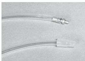
Bleed Fittings

Filler Bottle Attachment
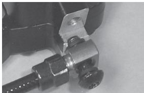
G1 Caliper Hose Assembly

G2 Caliper Hose Assembly
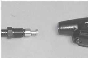
HFX-9 Hose Assembly
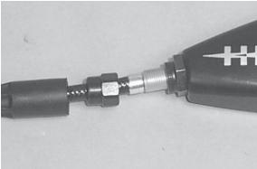
HFX-Mag Hose Assembly