SX300A - Enceinte acoustique active ELECTRO-VOICE - Notice d'utilisation et mode d'emploi gratuit
Retrouvez gratuitement la notice de l'appareil SX300A ELECTRO-VOICE au format PDF.
| Type de produit | Enceinte acoustique active |
| Marque | Electro-Voice |
| Modèle | SX300A |
| Dimensions (H x L x P) | 250 mm x 188 mm x 100 mm (profondeur arrière) + 38 mm (saillie avant) |
| Poids total | 3,894 kg |
| Alimentation | 115 V, 230 V ou 240 V AC (sélectionnable par câblage) |
| Puissance de sortie (continue) | 130 W sous 8 Ω, 200 W sous 4 Ω |
| Réponse en fréquence | 42 Hz - 20 kHz (-3 dB), filtre passe-haut actif 24 dB/octave |
| Distorsion (THD) | < 0,01% à 1 kHz |
| Rapport signal/bruit | > 105 dB (pondéré) |
| Entrée | XLR 3 broches femelle, symétrique, impédance 20 kΩ |
| Commandes | Volume externe (0-270°), commutateur Ground/Lift, commutateur actif Full Range/Subwoofer (42 Hz/125 Hz), interrupteur marche/arrêt |
| Protections intégrées | Délai de mise sous tension, court-circuit, thermique (80°C), DC offset, SOAR, fusibles primaire/secondaire |
| Entretien et nettoyage | Débranchez l’alimentation avant tout entretien. Nettoyez l’extérieur avec un chiffon doux et sec. N’utilisez pas de solvants ni d’eau. |
| Sécurité | Présence de tensions dangereuses à l’intérieur (jusqu’à 140 V DC). Confiez les réparations à un technicien qualifié. Utilisez le fusible adéquat. |
| Pièces détachées et réparabilité | Un manuel de service détaillé (P300Sx) est disponible avec la liste complète des pièces et les procédures de réglage interne. Adressez-vous à un centre agréé Electro-Voice. |
| Indice de protection | Usage intérieur uniquement |
FOIRE AUX QUESTIONS - SX300A ELECTRO-VOICE
Questions des utilisateurs sur SX300A ELECTRO-VOICE
0 question sur cet appareil. Repondez a celles que vous connaissez ou posez la votre.
Poser une nouvelle question sur cet appareil
Téléchargez la notice de votre Enceinte acoustique active au format PDF gratuitement ! Retrouvez votre notice SX300A - ELECTRO-VOICE et reprennez votre appareil électronique en main. Sur cette page sont publiés tous les documents nécessaires à l'utilisation de votre appareil SX300A de la marque ELECTRO-VOICE.
MODE D'EMPLOI SX300A ELECTRO-VOICE
Service Manual for the Sx300a Amplifier (P300Sx)
TABLE OF CONTENTS
SAFETYWARNING 3
DESCRIPTION OF THE P300SX 3
INPUT CIRCUIT DESCRIPTION 3
PROTECTION CIRCUIT 3
AMPLIFIER SECTION 3-4
POWER SUPPLY 4
EQUIPMENT NEEDS FOR TESTING 4
INTERNAL AMPLIFIER ADJUSTMENTS 4-5
5
P300SX FINAL TESTING PROCEDURE 5-6
P300SX POWER RATINGS 7
VOLT AND VOLT TRANSFORMER 7
PARTS LIST 8
SAFETYWARNING
These amplifiers connect directly to the mains supply. Thus depending on what country you are in, there may be at any time 115V, 230V, or 250V AC exposed. In addition, DC voltages on the order of 140V are generated by the power supply. These DC voltages can remain for a long time (1/2 hour or longer) after the unit has been switched off or after the mains voltage has been removed.
P300Sx IN EVI PRODUCTS
The P300Sx is used to power the Electro-Voice Sx300a two-way Speaker System and is mounted inside the back of the enclosure.
DESCRIPTION OF THE P300SX
P300Sx Specifications
symmetrical input via XLR-3 pole female
- use with or without subwoofoers with 42Hz/125Hz active high-pass filter switch
external volume control (0 to 270^
ground/float switch
on-off switch with lamp
- mains breaker (manually resettable)
3-pole universal mains socket on chassis
- speaker output chassis socket, to driver passive subwoofer or any other system
- autocalibration of output DC offset
- numerous protection features (see below)
total weight including transformer: 3.894 Kg
available with 115V, 230V or 240V mains input
Distortion measured at 0.5 dBu below clipping into 4-ohms:
THD%<0.01kHz
IMD (SMPTE) <0.03 60 Hz - 7 kHz/4:1
Frequency response (0 dBu reference at 1 kHz):
-1.24 dBu at 20 kHz
-3 du switchable at 42 Hz or 125 Hz
24 dB per octave below switched frequency
Signal to noise (Weighted Average) >105 dB (ref. 0 dB/4-ohms
Damping factor >100 (1 kHz) 8-ohms
Output DC offset < 0.1mV (autocalibrating system)
Maximum dissipation < 400 Watts
Input impedance: 20 Kohms (balanced)
Power Output into resistive load:
Continuous into 8 ohms 130 Watts
Continuous into 4 ohms 200 Watts
Weight
P300Sx 1,726 grams
Crossover for P300Sx 654 grams
Total P300Sx 3,894 grams
Dimensions
Height 250 mm
Width 188mm
Rear depth with crossover 100 mm (P300Sx)
Front protrusion (cooling fins) 38 mm
P300Sx INPUT CIRCUIT DESCRIPTION
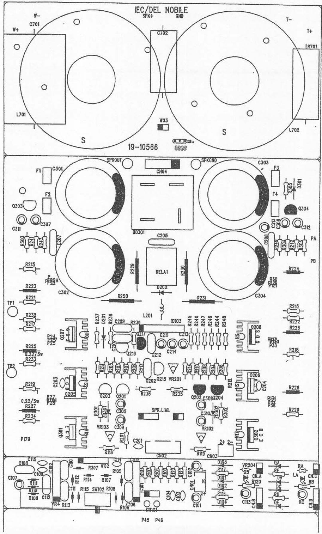
Typically the components on the input circuit have numbers that are in the 100 range (e.g. IC101, C104, R112,...).
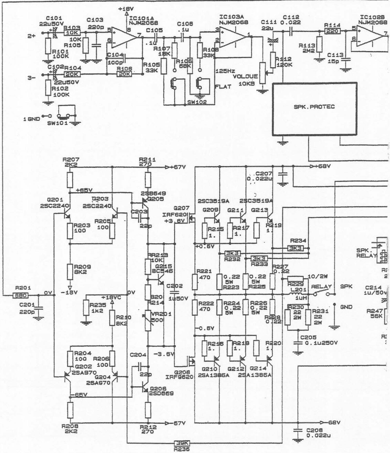
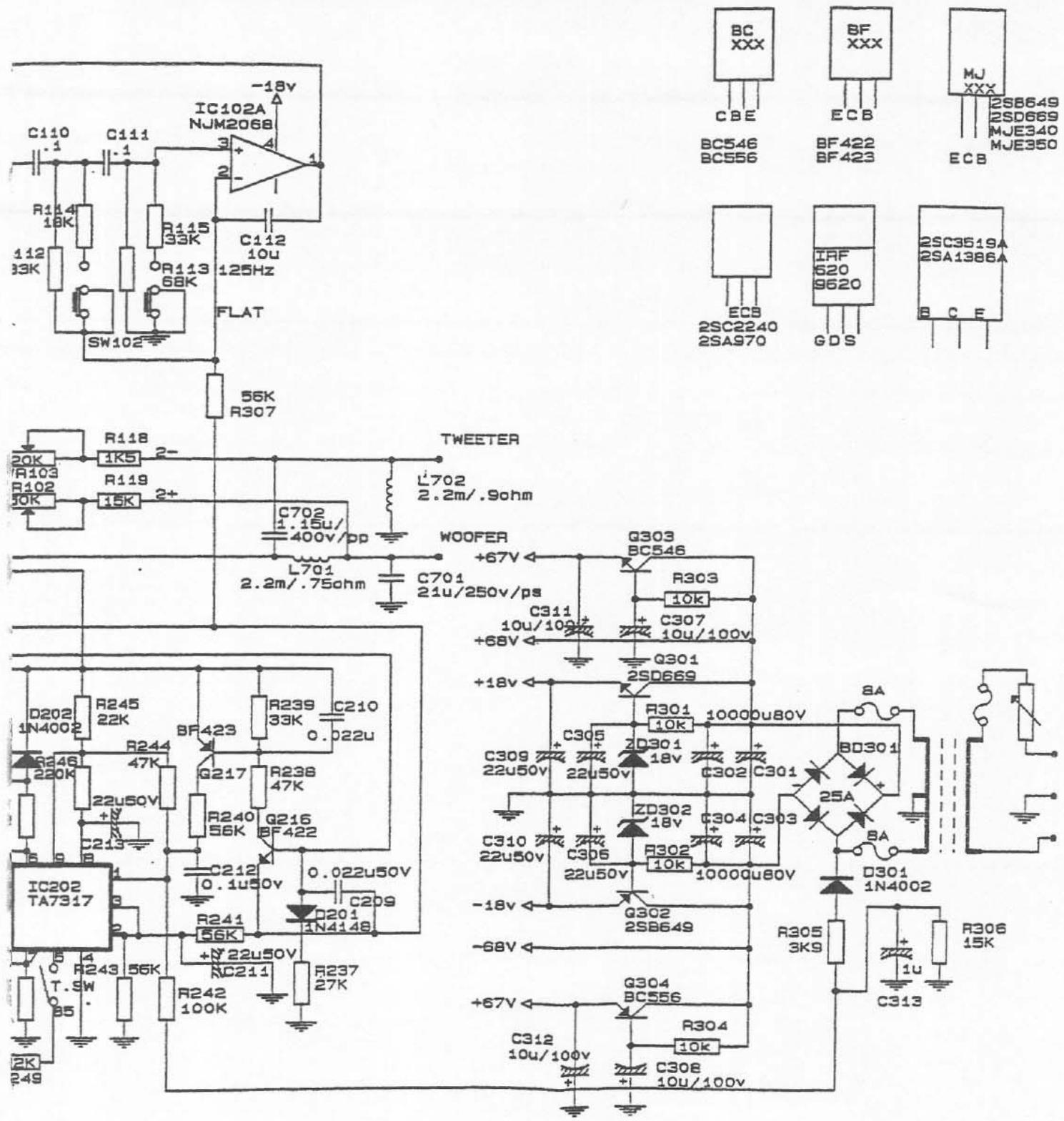
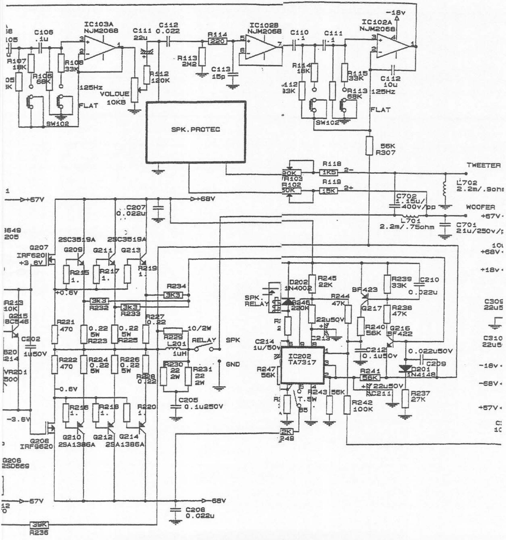
The input circuit for the P300Sx consists of two double integrated circuits. The first integrated circuit IC101A provides the mixing for the balanced 20 Kohms input. IC102B is a high-pass Sallen-Kay two-pole Butterworth 12 dB/octave filter switchable between 125Hz and 42Hz . IC102B provides the impedance follower for the volume control and the speaker protection circuits. IC102A provides a second high-pass Sallen-Key two-pole Butterworth 12 dB/octave filter switchable between 125Hz and 42Hz .
PROTECTION CIRCUITS
turn-on delay (approx. 4-5 seconds)
short-circuit protection
max temperature protection (80^)
- automatic zeroing of the DC output voltage
- SOAR (protection against any combination of output voltage or signal type and frequency, output load, mains voltage)
- fuses at primary and secondary
- speaker protection processing
AMPLIFIER SECTION
Typically, the components associated with the main amplifier section have numbers in the 200 range (e.g. R201, C208, Q210, L201,...).
The power amplifier is designed to be able to efficiently drive a wide range of output loads as well as to react well to capacitive loads.
The first part of the main circuit board of the power amplifier is the input differential pair. In fact, in these amplifiers, everything is perfectly
symmetrical. Consequently, there are two differential pairs (Q201-Q203 and Q202-Q204). The differential pairs take as input the signal from the input circuit board and the NFB (negative feed back) signal. They significantly reduce the harmonic distortion of the overall amplifier as well as maintain an automatic zero calibration of the DC voltage on the amplifier output so that it may be directly connected to the speaker.
The differential pairs are followed by a standard VAS (voltage amplifier stage) transistor (Q205 and Q206). To linearize the VAS at high frequencies a local NFB shunt is used. The signal is then feed into the MOSFET driver stage.
The power amplifier circuit is what is commonly called a "simple quasicomplementary" output configuration running in class B mode using MOSFET's as the drivers. The main power transistors are BJT's rather than MOSFET's because they produce significantly less distortion. The power transistor bias voltage is provided by a standard setup.
Note, if the speaker limiting circuits are properly adjusted, the amplifier should never clip the output, and consequently, the distortion should always remain at very low values.
POWER SUPPLY
Typically, the components associated with the main amplifier section have numbers in the 300 range (e.g. ZD301, C302, Q303,...).
The power supply consists of a toroidal transformer fused in the primary and the secondary. The nominal output of 54 Volts of the secondary is rectified with a diode bridge. The rectified output then feeds three separate DC supplies. The first is the high voltage unregulated rails supply of ± 68V (see below for details). This is the main supply to the power transistors and is heavily filtered. The second output is a high voltage regulated supply of used for the voltage amplification and driver stages of the main amplifier. The third supply is a low voltage regulated supply of ± 18V used on the input circuit board for the intergrated circuit chips and in the differential amplifier of the main amplifier.
Measured at fuse F1, the transformer secondary at no load should provide approximately 54.5 V with the primary voltage at 228.2. At 200 Watts output into a 4-ohms resistor, the transformer secondary voltage should be approximately 45.2 V with a primary voltage of 224.2 V.
The unregulated power amplifier rails voltage marked ± 68V on the schematic should read approximately 73.7 volts with no load, and 53.7V at 200 Watts output into a 4-ohm resistor.
The regulated rails voltage marked ± 67V on the schematic should read approximately 72.65V no
load, and 52.8V at 200 Watts output into a 4-ohm resistor.
EQUIPMENT NEEDS FOR TESTING
In order to make the driver protection adjustments, you will need:
- a sine wave generator
- an AC voltmeter
- an 8 ohm resistive load capable of dissipated 200 Watts (average) of power
In order to adjust the quiescent bias voltage, you will need:
a DC voltmeter capable of reading 5mV
- an 8-ohm resistive load capable of dissipated 200 Watts (average) of power
Additional useful equipment:
- an oscilloscope
a spectrum analyzer
INTERNAL AMPLIFIER ADJUSTMENTS
The P300Sx has three variable resistors mounted on the circuit board that are used to make the internal adjustments of the amplifier. Two of the variable resistors are used to adjust the driver protection circuits in the P300Sx to prevent overload of the tweeter and the woofer drivers. The third variable resistor is used to set the quiescent bias voltage on the power output transformers.
Transducer Overload Protection Adjustment Procedure
VR102 is a variable resistor that sets the maximum power delivered to the woofer on the P300Sx.
- Connect the output of the amplifier directly to a 4-ohm resistive load capable of dissipating at least 200 Watts of power. The crossover circuit should not be connected (or should be bypassed).
- Put an AC voltage meter across the amplifier output capable of measuring up to 30V .
- Ensure that the driver sensing wire (2) is connected to the output.
- Put the volume control to minimum.
For the P300Sx, supply a sine wave input of 4 V at 1 kHz. - Slowly increase the volume control while adjusting VR102 to make the amplifier output become 28.3 V when the volume control is at maximum.
Once you have properly set VR102, we recommend that you apply a small amount of electrical paint to the outside of the shaft to prevent it from turning from acoustical vibrations.
NOTE: If VR102 does not change the output volt
age of the amplifier, it is probably because the driver sensing wire is not connected.
VR103 is a variable resistor that sets the maximum power delivered to the tweeter on the P300Sx.
- Connect the output of the amplifier directly to as a 4-ohm resistive load capable of dissipating at least 35 Watts of power. The crossover circuit should not be connected (or should be by passed).
- Put an AC voltage meter across the amplifier output capable of measuring up to 15V .
- Ensure that the driver sensing wire (2-) is connected to the output.
- Put the volume control to minimum.
Supply a sine wave input of 4V at 1 kHz. - Slowly increase the volume control while adjusting VR103 to make the amplifier output be come 11V when the volume control is at maximum.
- Once you have properly set VR103, we recommend that you apply a small amount of electrical paint to the outside of the shaft to prevent it from turning from acoustical vibrations.
NOTE: If VR103 does not change the output voltage of the amplifier, it is probably because the driver sensing wire is not connected.
P300Sx Bias Adjustment Procedure
This procedure adjusts the power transistor quiescent bias current using VR201.
- Before powering on the amplifier, adjust VR201 to be in the full clockwise position. Note, in the P300Sx to access VR201, which is on the main circuit board, you may have to disconnect the passive crossover filter. Do so by removing the red and black output wires, remove the white driver protection wires by pulling the plug from the main circuit board, finally, remove the four screws that hold the crossover filter board to the main circuit board.
- Set the volume control to minimum.
- Leave the driver output unconnected (i.e. no driver, no resistive load)
- Connect a DC voltage meter to TP1 and TP2 on the main circuit board with the positive input on TP1 and the negative on TP2.
Power on the amplifier. - Allow the amplifier to warm up for approximately 5 minutes or longer.
- Slowly turn VR201 until the voltage meter reads about 2.5mV (must be between 2mV and 8mV ).
- When the bias voltage is adjusted properly and the amplifier is switched on from a cold stage, the bias voltage will read approximately 20mV
but will decrease during warm-up to the operating voltage of 2.5mV
Once you have properly set VR201, we recommend that you apply a small amount of electrical paint to the outside of the shaft to prevent it from turning from acoustical vibrations.
NOTE: If the bias voltage is set too low (below 2mV ), the amplifier will generate significantly more harmonic distortion. If the bias voltage is set to high (above 8mV ), the amplifier will run hot and at high bias voltages, it may overheat.
INITIAL TESTING
The first thing to do is to give the amplifier a good visual check. This point should not be overlooked as often one can spot many potential problems visually. Look for parts that are bent or wires that are frayed or broken. Check that none of the wires on the main circuit board touch the chassis. Check the main circuit board for signs of discoloring, overheating or burning.
If the unit arrives in a "dead" condition, check that each of the three fuses is good. Two of the fuses are on the back of the main circuit board, the third fuse is in a fuse holder on the front panel. Remove this fuse, check it, and replace it if necessary.
If the unit passes a visual check, connect the unit to AC mains power, being careful to note whether it is a 110V, 220V or a 240V unit. In doubt, temporarily replace the transformer with one with which you are familiar. Connect the transformer output to the plug on the main PCB and apply AC mains power.
Check that the power switch lights up. Within 4 to 5 seconds of applying the AC power, you should hear the distinctive click of the output relay at it engages. If not, check the AC power source, the fuses, and the transformer power cable.
The DC voltage at the amplifier output should be less than ± 6mV
With the speaker protection sensing wires removed, and with an 8-ohm resistive load and a sine wave input at 1kHz at 0.775V , you should measure 14.4V across the load. At 2V input, you could measure approximately 37V across the load and this should be the onset of clipping. The output should be a well formed sine wave before the clipping voltage is reached.
P300Sx FINAL TESTING PROCEDURE
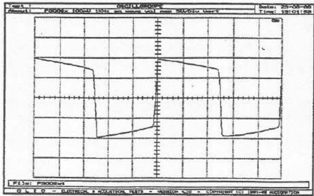
A good test of the amplifier is to feed a 1kHz square wave into the input and observe the waveform across an 8-ohm resistor.
- Set the front panel slider switch to "Full Range"
- Connect an 8-ohm resistive load to the output.
-
Connect a signal generator set at 100mV ; 1 kHz square wave to the input.
-
Connect a high-bandwidth (10 Megahertz or better) oscilloscope to the output.
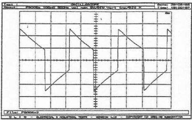
As a second test, try a 300Hz square wave.
- Set the front panel slider switch to "Full Range".
- Connect an 8-ohm resistive load to the output.
- Connect a signal generator set at 100mV at 300Hz square wave to the input.
- Connect a high-bandwidth (10 Megahertz or better) oscilloscope to the output.
P300SX PERFORMANCE GRAPHS Front Panel Switch in "Full Range" Position
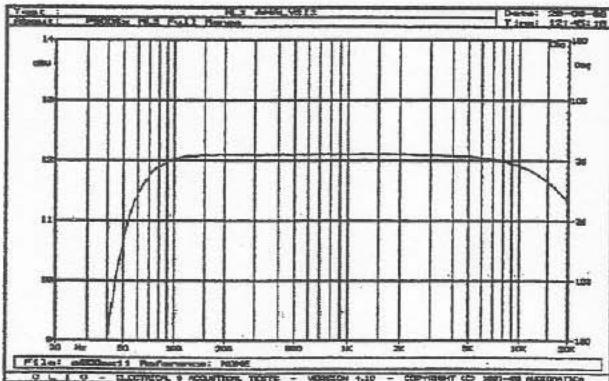
In the full range position, the -3 dBu point of the active high-pass filter is at 42Hz . Below 42Hz , the signal falls off at 24 dB per octave thus protecting the driver from infrasonic (subsonic) sig
nals. Without the high-pass filter, infrasonic signals would cause a significant increase in distortion or worse, physical damage to the driver.
Normally, the P300Sx is operated in the "Full Range" position when no subwoofer is present.
Too Much Hum (50 Hz or 60 Hz)
There are two simple causes of excessive hum. The first is improper setting of the FLT/GND toggle switch located on the front panel below the indication GROUND. Normally, this switch should be in the GND position. The second most frequent cause of excessive hum is ground loops caused by the mains supply. All amplifiers and preamplifiers in the system must be connected to the same mains supply. If all equipment connected to the system is not connected into the same single mains supply, there is a possibility for ground loops and hence excessive hum.
Frequent Shutdowns
The most likely cause of frequent shutdowns is overheating of the amplifier. See the description above.
It is possible that with very high volumes, the fuse will make intermittent contact causing the amplifier to power on and off at more or less random times. If the fuse holder is of the type where the fuse cover cap is round and secured by making approximately one quarter turn, the problem can be corrected by removing the fuse cover and stretching the spring. Gently remove the spring from the fuse cover cap with a pair of needle nose pliers taking care not to damage the delicate vertical metallic tab inside the fuse cap. With your fingers or with the pliers, stretch the fuse spring to 1.5 to 2 times its length. Replace the spring in the fuse cap taking extreme care not to bend or dmage the vertical metallic tab inside the cap. The wider end of the spring goes in first. Place the fuse in the cap (important), then screw (one quarter turn) the cap back into the fuse holder. The stretched fuse spring will hold the fuse in place more tightly and should prevent future intermittent contact.
Shutdowns when the music volume is suddenly increased
First, verify that the power transistor bias voltage is properly set and that the driver limiting voltage is correctly set. If the problem persists, careful checking of all the protection circuits may indicate the problem allowing you to resolve it. If the problem is not apparent, redo the Driver Overload Protection Adjustment Procedure but set the voltage via VR102 to 24.5 V instead of the standard 28.3 V. This reduces the maximum average power delivered to the driver from 200 Watts to 150 Watts thus reducing overheating and overloading prob
lems with the power transistors.
P300Sx POWER RATINGS
Measured Values (sine wave 1 kHz)
| 8 Ohms | 4 Ohms | |||
| Time On ms | Time Off 480 ms | Time Off 100 ms | Time Off 480 ms | Time Off 1000 ms |
| 20 | 225 W | 225 W | 450 W | 450 W |
| 50 | 200 W | 210 W | 330 W | 360 W |
| 100 | 175 W | 195 W | 290 W | 312 W |
| 250 | 145 W | 156 W | 230 W | 250 W |
| 500 | 145 W | 145 W | 230 W | 230 W |
| 1000 | 136 W | 136 W | 220 W | 220 W |
| Continuous 136 W 220 W | ||||
| - Watts - average - | ||||
| Values measured with 230 V AC at mains input using type M 010 transformer | ||||
115 VOLT AND 230 VOLT TRANSFORMER
The 115 Volt and 230 Volt setups use the same transformer since the primary consists of two 0-115 V input windings. Thus the same transformer may be used for 115 V mains or 230 V mains by rewiring the primary taps. The transformer specification is
P/N #15345
O/P 55 V - 0 V - 55 V
yellow black red
I/P 115 V - 0 V - 0 V - 115 V
black grey brown white
240 VOLT TRANSFORMER FOR AUSTRALIA
Mains voltages up to 480V have been measured in Australia. When these voltages are fed into the 230V transformer, the amplifier under heavy load conditions will frequently shutdown due to excessive current in the power transistors. Consequently, for Australia, there is a special "high-mains" transformer.
The Australian transformer is identified as P/N #15352.
| P300Sx Parts List | Resistor, 680 Ohm 1/4 Watt | 46917 | |
| Amplifier, P300Sx 110V | 84860 | Resistor, 68K Ohm 1/8 Watt | 46918 |
| Amplifier, P200Sx 230V/240V | 84861 | Resistor, 8.2K Ohm 1/4 Watt | 46919 |
| Capacitor, .022uF 250V | 42827 | Resistor, Variable 10KB×1 15mm | 46890 |
| Capacitor, .022uF 50V | 42828 | Switch, Power 10A DPDP Rocker | 56229 |
| Capacitor, .1uF 250V | 42829 | Switch, Slide 2T 4P | 56230 |
| Capacitor, .1uF 50V | 42830 | Switch, Toggle 3A | 56231 |
| Capacitor, 10000uF 80V | 42825 | Thermal Protector | 46920 |
| Capacitor, 10uF 50V | 42832 | Thermistor, 5 Ohm, 7A | 46922 |
| Capacitor, 15PF 50V | 42833 | Transformer, Toroidal (Universal) | 15345 |
| Capacitor, 1uF 50V ± 20% | 42834 | Transformer, Toroidal (240V) | 15352 |
| Capacitor, 1uF 50V ± 5% | 42835 | Transistor, 2SA1386A | 48-03038058 |
| Capacitor, 220PF 50V | 42836 | Transistor, 2SC3519A | 48-03038056 |
| Capacitor, 22PF 50V | 42837 | Transistor, 2SA970BL | 48-03028809 |
| Capacitor, 22uF 50V | 42838 | Transistor, 2SB649AC | 43004 |
| Coil, Air 2.2 MH .9 Ohm | 35612 | Transistor, 2SC2240BL | 48-03124824 |
| Coil, Air 2.2MH .75 Ohm | 35614 | Transistor, 2SD669AC | 43003 |
| Diode, 1N4002 | 48-01-037276 | Transistor, BC546B | 43005 |
| Diode, 1N4148 | 48-01-122601 | Transistor, BC556B | 43016 |
| Diode, Bridge 400V 25A | 43011 | Transistor, BF422 | 43006 |
| Diode, RET 800V 1A | 43012 | Transistor, BF423 | 43007 |
| Diode, Zener 18V 1/2 Watt | 43010 | Transistor, FET IRF620 | 43036 |
| Fuse Holder | 41005 | Transistor, FET IRF9620 | 43037 |
| Fuse Holder, Main Power | 41006 | Fuse, 2A Sx200mm | 48-03-051023 |
| Fuse, 8A 5x20mm | 41002 | Fuse, 4A Sx200mm | 48-03-052406 |
| IC, NJM2068DL | 17-01-037412I | ||
| IC, TA7317P | 17-01-124804 | ||
| Jack, XLR Female | 17353 | ||
| Jack, XLR Male | 17352 | ||
| Knob | 20668 | ||
| Relay, 24V 12A SPDT | 56228 | ||
| Resistor, .22 Ohm | 46893 | ||
| Resistor, 1 Ohm 1/4 Watt | 46894 | ||
| Resistor, 1.2K Ohm 1/4 Watt | 46900 | ||
| Resistor, 1.5K Ohm 1/4 Watt | 46901 | ||
| Resistor, 10 Ohm 2 Watt | 46891 | ||
| Resistor, 100 Ohm 1/4 Watt | 46895 | ||
| Resistor, 100K Ohm 1/4 Watt | 46896 | ||
| Resistor, 10K Ohm 1/4 Watt | 46897 | ||
| Resistor, 15K Ohm 1/4 Watt | 46898 | ||
| Resistor, 18K Ohm 1/8 Watt | 46899 | ||
| Resistor, 2.2K Ohm 1/4 Watt | 46907 | ||
| Resistor, 2.5M Ohm 1/8 Watt | 46909 | ||
| Resistor, 2.7K Ohm 2 Watt | 46908 | ||
| Resistor, 22 Ohm 2 Watt | 46892 | ||
| Resistor, 220 Ohm 1/8 Watt | 46902 | ||
| Resistor, 220K Ohm 1/4 Watt | 46903 | ||
| Resistor, 22K Ohm 1/4 Watt | 46904 | ||
| Resistor, 270 Ohm 1/4 Watt | 46905 | ||
| Resistor, 27K Ohm 1/4 Watt | 46906 | ||
| Resistor, 3.3K Ohm 1/4 Watt | 46912 | ||
| Resistor, 3.9K Ohm 1/4 Watt | 46913 | ||
| Resistor, 33K Ohm 1/4 Watt | 46910 | ||
| Resistor, 33K Ohm 1/8 Watt | 46911 | ||
| Resistor, 47K Ohm 1/4 Watt | 46914 | ||
| Resistor, 56K Ohm 1/4 Watt | 46915 | ||
| Resistor, 56K Ohm 1/8 Watt | 46916 |