604G16-2 - Cuisiniere gaz NESTOR MARTIN - Notice d'utilisation et mode d'emploi gratuit
Retrouvez gratuitement la notice de l'appareil 604G16-2 NESTOR MARTIN au format PDF.

| Type de produit | Cuisinière gaz |
| Marque | NESTOR MARTIN |
| Modèle | 604G16-2 |
| Alimentation électrique | 230 V ~ 50 Hz |
| Alimentation gaz | Gaz naturel (convertible en butane, propane, butane-air, propane-air) |
| Puissance totale nominale | 13,37 kW |
| Brûleurs de la table de cuisson | 4 brûleurs : avant droit rapide amélioré 3,26 kW, arrière droit semi-rapide 1,75 kW, avant gauche semi-rapide 1,75 kW, arrière gauche rapide 2,62 kW |
| Four | Four traditionnel à gaz avec thermocouple de sécurité |
| Gril | Gril à gaz avec thermocouple de sécurité |
| Fonctions supplémentaires | Minuteur, éclairage du four, tournebroche |
| Accessoires fournis | Plateau de cuisson, grille du four, lèchefrite, tournebroche |
| Poids | Environ 51 kg |
| Nettoyage | Émail lisse ou catalytique selon version ; nettoyage manuel pour émail lisse, autonettoyant pour catalytique |
| Sécurité | Thermocouple sur brûleurs four et gril, allumage électrique |
| Installation | Sur pieds réglables, raccordement gaz à droite ou gauche, nécessite une ventilation adéquate |
| Réparabilité | Injecteurs interchangeables, ampoule four remplaçable, pièces détachées disponibles |
FOIRE AUX QUESTIONS - 604G16-2 NESTOR MARTIN
Questions des utilisateurs sur 604G16-2 NESTOR MARTIN
0 question sur cet appareil. Repondez a celles que vous connaissez ou posez la votre.
Poser une nouvelle question sur cet appareil
Téléchargez la notice de votre Cuisiniere gaz au format PDF gratuitement ! Retrouvez votre notice 604G16-2 - NESTOR MARTIN et reprennez votre appareil électronique en main. Sur cette page sont publiés tous les documents nécessaires à l'utilisation de votre appareil 604G16-2 de la marque NESTOR MARTIN.
MODE D'EMPLOI 604G16-2 NESTOR MARTIN
IN F0
U
USER AND INSTALLATION MANUAL
GEBRAUCHSANWEISUNG
GAS COOKERS
GAS HERDE
Electrolux
PARTRESERVEDFORUSER 4
11. TECHNICAL INFORMATION 4
1.1 Hob 4
1.2 Oven 4
1.3 Options available from your dealer 4
2. PRECAUTIONS ON USE 5
3. DESCRIPTION OF COOKER 6
3.1 Control panel 6
3.2 Hob 6
3.3 Minute minder 6
3.4 Oven
3.5 Oven accessories 7
4. USER'S GUIDE 8
4.1 Turning on the burners 8
4.2 Ignition of oven burner 8
4.3 Lighting the grill burner 9
4.4 Spit 9
5. A FEW WORDS OF ADVICE 10
5.1 For cooking on the hob 10
5.2 For cooking in the oven 103
5.3 For cooking using the grill 12
6. COOKING GUIDE 13
6.1 Oven cooking guide 13
6.2 Guide to cook with the grill 14
7. CLEANING 15
7.1 Pan support grills 15
7.2 Burners 15
7.3 Hob top, controls and door 154
7.4 Cleaning the grill 15
7.5 Cleaning a smooth enamel oven 15
7.6 Cleaning a catalytic enamel oven 15
8. WHAT TO DO IF A PROBLEM ARISES 16
9. DATAPLATE 17
SECTION RESERVED FOR INSTALLER 18
11. INSTALLATION SAFETY INSTRUCTIONS 183
2. INSTALLATION OF COOKER 19
2.1 Positioning of cooker 193
2.2 Electrical connection 193
2.3 Gas connection 195
3. MAINTENANCE 21
3.1 Disassembly and assembly of hob cover 21
3.2 Replacing the oven lamp 21
4. CHANGING GAS 22
4.1 Change of hob injectors 223
4.2 Change of grill injector 23
4.3 Changing the oven injector 231
4.4 Air adjustment of hob burner 23
4.5 Air adjustment of grill and oven burner 243
4.6 Adjusting low flow-rates of hob burners 253
4.7 Adjusting the low flow-rate of the oven burner 253
1. TECHNICAL INFORMATION
Type of cooker 6130
Cooker adjusted for natural gas
Conversion possible to butane, propane, butane-air, propane-air gas for France
Conversion possible to butane and propane gas for Belgium
Electrical connection. 230 V 50 Hz
Nominal calorific output 13.37 kW
Weight approx. 51 kg
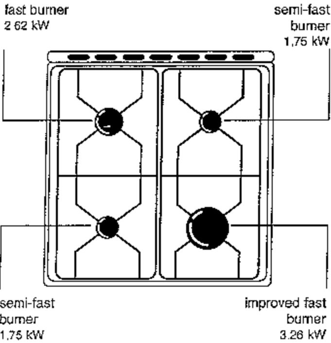
1.1 Hob
Front right burner fast improved bumer 3.26 kW
Rear right burner semi-fast burner 1.75 kW
Front left burner semi-fast burner 1.75 kW
Rear left burner.. fast burner 2.62 kW
1.2 Oven
Ovenburner gas
Grill gas
1.3 Options available from your dealer
Removable door protection screen
White Ref.: P/N 998 97 W
No.949916501
Brown. .Ref.: P/N 998 97 M
No.949911101
The marking C€ corresponds to the application of gas appliance Directive 90/396.
2. PRECAUTIONS ON USE
-
Read the instructions carefully and reep them: they are designed to enable you to get the best out of your cooker.
Before using your cooker for the first time, heat it empty to remove the smell of insulation and protective grease used in production: -
lift the cover
- remove the protective film from the trim as well as the stickers
- remove any advertising stickers
heat the oven by turning the oven control to maximum for 30 minutes then to the grill position for approximately 10 minutes.
During this operation your cooker may emit some smoke. Ventilate the room to limit the smell and the amount of smoke.
Take the precaution of washing the oven accessories (grill, pastry tray, roasting-pan).
- The use of a gas cooker will produce heat and humidity in the room it is installed. Be sure to air the kitchen properly: keep the natural aeration orifices open or install a mechanical aeration arrangement.
- Intensive use of the oven for long periods of time may require supplementary aeration by opening of window or more efficient aeration, for instance by increasing the mechanical ventilation power, if such a device is available.
- Your cooker is designed for cooking and for no other purpose.
For safety.
Wait until the top of the hob has cooled before closing the cover.
- Remove any spilled matter from the cover (e.g. water from a vase).
- Never pull your cooker by the door handle.
Before cleaning the oven, make sure that none of the parts is energized. All the controls must be turned OFF.
- Be sure to keep the burner rings clean at all times; if they are dirty, they could cause incorrect ignition
If you have removed these rings to clean them, make sure that:
The burner rings are stable on the burners
The caps are in place.
- Never leave anything on the hob when the burners are being used (dish cloths, aluminum foil, etc.).
The front of the cooker will be hot during use and cleaning. Keep young children away from it. - Do not store household or flammable products in the drawer.
- Never place aluminum foil directly in contact with the bottom plate because it could damage the enamel.
- Never use the roasting-pan as a roasting dish.
- Change the gas pipe shortly before expiration as marked upon it.
Never use propane gas cylinders in your kitchen or any other closed room.
In the event of an operating Incident, first refer to the chapter entitled «In the event of problems, what should I do?». If the anomaly persists after the various points have been checked, contact your dealer, your after-sales service or the consumers advisory service. Indicate the model and number of your cooker that appear on the dataplate. Do not try to repair your cooker yourself as you could run the risk of serious injury.
Always demand original, manufacturer-certified
spare parts

3. DESCRIPTION OF COOKER
3.1 Control panel
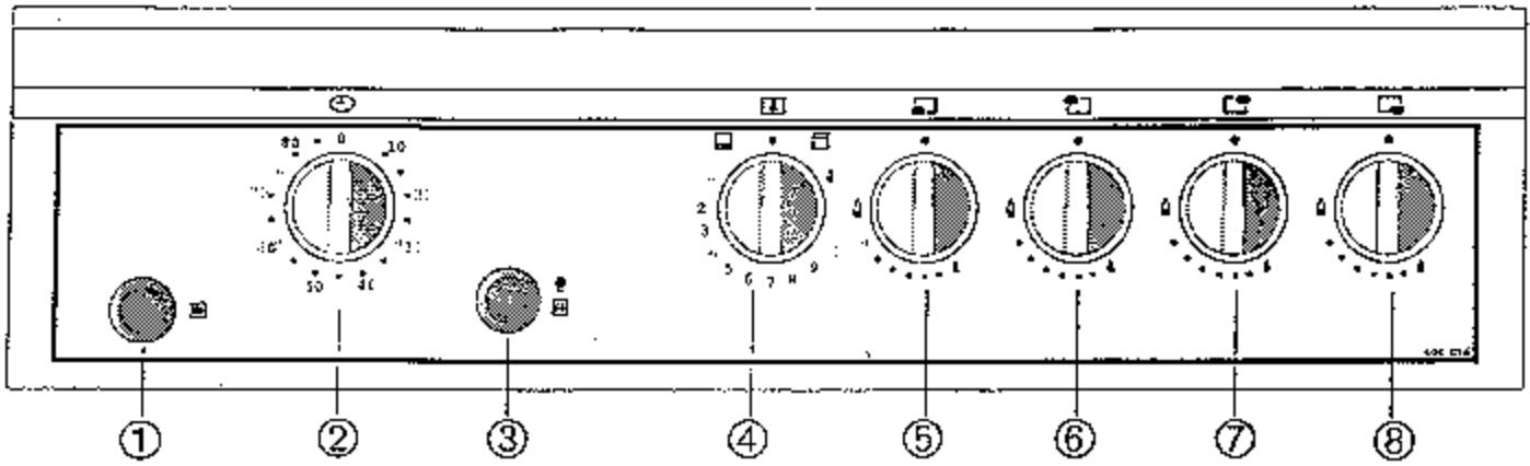
(1)
Electric ignition of burners
②
Minute minder
③
Oven lighting and spit control
(4)
Oven and grill control

to ⑧
Hob burner controls
3.2 Hob
There are four burners on the hob with a progressive slow-down system.
The hob is characterized by its easy adjustment offering:
easy setting of any flame from very high to very low
- identification of the position concerning each type of cooking method, according to your own system, so that you can find the position without trial and error.
3.3 Minute minder
The minute minder is used for choosing the cooking time.
- When the cooking time has elapsed, the minute minder will sound but will not stop the cooking process.
- Turn the oven control back to the OFF position.
Minute minder
3.4 Oven
The oven can be used as a tradition oven or as a grill. Both methods cannot be used simultaneously.
The oven burner has a thermocouple safety device.
In the traditional mode adjustment is by 10 graduations.
To switch from traditional cooking to grill cooking, the oven must be turned off and the grill turned on.
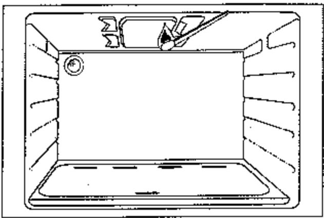
3.5 Oven accessories
Your cooker is equipped with:
1 baking tray
1 oven shelf
1 roasting-pan
Baking tray
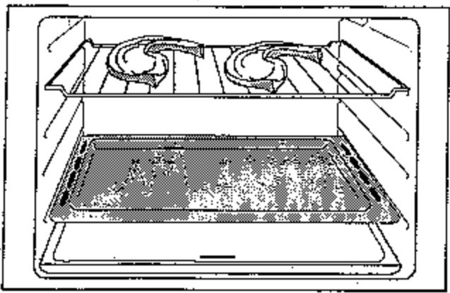
The baking tray is used for cooking or warming up pizzas, small cakes placed directly on the plate. it must be placed upon the oven shelf.
Oven shelf
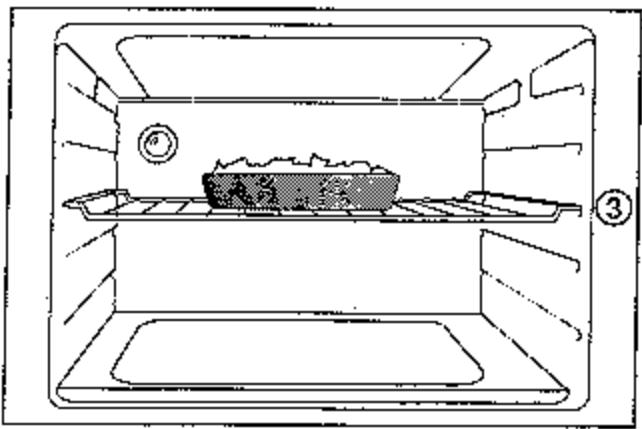
The oven shelf is suitable for roasts gratins, pastry fats, etc.
You can use the grill turned up or down so that your dishes are adjusted with respect to the source of heat. For particularly heavy preparations (more than 4 kg), place the oven shelf turned up.
Roasting-pan
The roasting-pan is used to catch the juices from your grills. It also supports the spit.
It is not designed to be used as a cooking tray.
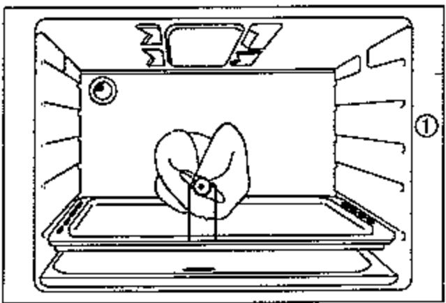
Spit
The spit consists of:
f spit
2 forks
2 supports
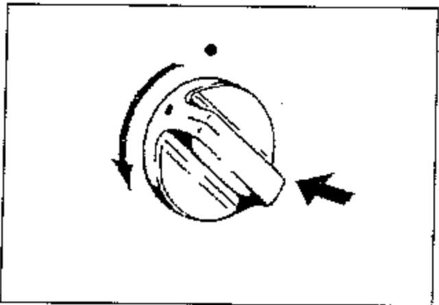
4.1 Turning on the burners
Your hob has «gradual idter» burners. They are characterized by particularly flexible adjustment and you can easily obtain any flame between maximum and minimum power.
To turn on the burners:
"Push and turn the chosen burner control counterclockwise and hold the control down.
- Push and release the electric ignition button to generate a spark. Repeat the operation until a flame appears.
or
apply a flame to the burner with the control turned on.
- Then hold the control down for 10 seconds.
If the burner goes out, repeat the operation while holding the control down for 15 seconds at most.
To turn off the burners:
Turn the control clockwise until it stops in the off position.
4.2 Ignition of oven burner
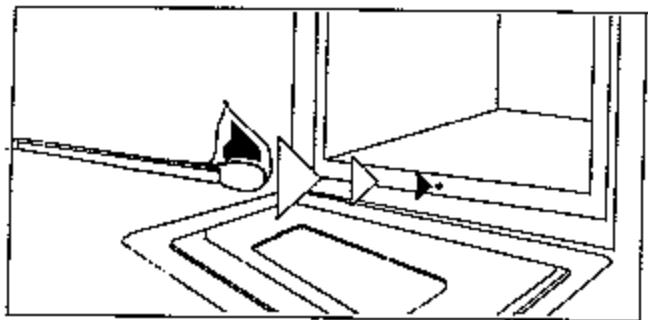
Open the oven door
- Push and turn the oven/grill control from right to left, to the maximum mark, and hold the control down.
At the same time, press and release the electric ignition button. Repeat the operation until a flame appears
or
apply a flame to the ignition orifice.
- Then hold the control down for 10 seconds or so to activate the oven safety device (thermocouple).
If the burner goes out, repeat the operation while holding the control down for 15 seconds at most. - Check for the flames through the front orifice of the bottom plate.
- Close the oven door.
If the oven burner goes out accidentally, turn the control to the off position then wait 1 or 2 minutes before turning on again.
4.3 Lighting the grill burner
- Open the oven door
Fush and turn the oven/grill control from left to right, to the position and hold the control down. - At the same time, press and release the electric ignition button. Repeat the operation until a flame appears or apply a flame to the burner
Then hold the control down for 10 seconds or so to activate the grill safety device (thermocouple).
If the burner goes out, repeat the operation while holding the control down for 15 seconds at most.
Check for flames in the grill
Close the oven door
If the oven burner goes out accidentally, turn the control to the off position then wait 1 to 2 minutes before turning it on again.
4.4 Spit
To insert the item to be roasted on the spit:
- slide a fork onto the spit, then the item to be roasted, making sure it is properly centered
-
then slide the second fork on the spit.
-
Lock the forks
- Attach the two spit supports to the roasting tray
- Place the spit on the supports and slide the tray into Runner ①
- Push the spit to engage the end in the motor drive square (hole in the back wall of oven)
- Turn on the grill
Turn on the spit
Close the oven door
To remove the roasted item:
- tum off the grill
stop the spit - pull gently on the roasting-pan
- take the roasting-pan/spit assembly out of the oven.
5.1 For cooking on the hob
Choice of recipients
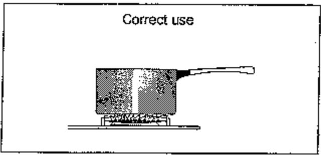
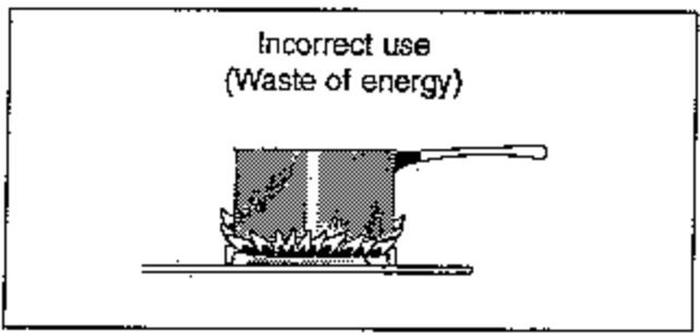
Always choose a recipient that is in proportion to the diameter of the burner being used.
12 to 20 cm diameter for the front left and rear right burners
20 to 26 cm diameter for the rear left bumper
26 to 30 cm diameter for the front right burner.
If you have to use a large base recipient (sterilizer, boiler, jam basin, couscous pan), move it slightly back towards the rear of the hob so that the base of the recipient does not overhang the front edge of the enamelled top to prevent the flames from overlapping and causing the control panel to overheat.
To ignite your burners properly
Always keep the burner rings absolutely clean. If they are not they could cause incorrect ignition.
If you have removed the burner to clean it, before igniting it make sure that:
theburner ringsarestableontheburners
the burner caps are in place.
5.2 For cooking in the oven
- Preheat the oven by choosing the normal cooking position:
8 minutes or so for Positions 1 to 5
15 minutes or so for Positions 6 to 8
- Warming and thawing precooked dishes use the traditional cooking position
Prick the skin of poultry and sausages with a fork before cooking them to prevent the skin from swelling and bursting.
Add fat just before the end of cooking - A sheet of aluminum unserted between the dish and the oven shelf will protect the oven bottom plate in
the event of spillage. This sheet of aluminum should not cover the entire grill surface.
Never place aluminum foil directly in contact with the base as it could cause damage to the enamel.
5.2.1 Choice of recipients
The amount of food to be cooked, and the great variety of materials used in cooking recipients and pastry tins in particular, may mean that you will need to change the indications given in the cooking table. According to your experience, you will find the setting best suited to your personal cooking methods.
The thickness, the conducting nature and color of the recipients influence the results of your cooking.
During the cooking process some foods increase in bulk. Accordingly, choose your recipients so that the uncooked preparation leaves the top third of the tin free.
To avoid excessive splashing, when cooking roasts use glass dishes with tall edges or metal pans (using glass ovenware only for gratin dishes or souffles).
5.2.2 Influence of recipients on cooking results
A Aluminum and earthenware or ovenware recipients will decrease the browning of the underside and preserve the moistness of your foods. We recommend these recipients for soft pastries, for cooking gratin dishes or roasts.
B Enamelled cast iron, tinned iron, glass and fire-proof porcelain, recipients with non-stick interior and colored external surfaces increase the browning of the underside and tend to cause foods to dry out more. We advise them for pies, quiches and other crusty dishes which need to be browned underneath and on top.
| You observe | What should I do? |
| Bottom not brown enough, not cooked enough or top too brown, overcooked | Use tin or dish type B or place in lower runner |
| Bottom too dark, overcooked top too light | Use tin or dish type A or place in higher runner |
5.3 For cooking using the grill
Preheat in the grill position.
Allow approximately 5 minutes for broiled meat.
Grilled food
Oil lightly if you so wish on both sides and place the meat directly on the grill.
Pface the roasting pan in Runner 1
Place the piece of meat as close to the grill as needed for searing. but no higher than Runner 4
- As soon as one side has browned, turn the meat over, without piercing it. Broil the other side
Salt at the end of cooking.
All cooking with the grill should be carried out with supervision and the door closed.
Au gratindishes
- Fface the dish on the oven shelf and slide the grill into Runners ③ or ④ .
- Leave the dish exposed to the heat of the grill for several minutes
The closer the dish to the heating element, the faster the browning process.
6.1 Oven cooking guide
It is necessary to preheat the oven in the same position as chosen for cooking.
Preheating time: 8 minutes for Positions 1 to 5
15 minutes for Positions 6 to 8
Cooking times are approximate and may vary according to the size of the item and your personal cooking methods.
| Dish | Thermostat position | Runner | Cooking time |
| MEATS | |||
| Beef | 5 - 6 | 3 | 1 5 min / 500 g |
| Leg of lamb | 5 - 6 | 3 | 1 5 min / 500 g |
| Pork | 4 - 5 | 3 | 3 5 min / 500 g |
| Veal | 4 - 5 | 3 | 30 min / 500 g |
| Poultry | 4 - 5 | 3 | 2 5 to 3 5 min per 500 g depending on thickness or size |
| FRS# | |||
| Large fish | 4 | 3 | 3 5 - 40 min |
| Small fish, slices and fillets | 4 | 3 | 20 - 30 min |
| VEGETABLES | |||
| Potatoes au gratin | 5 | 3 | 60 - 70 min |
| Stuffed tomatoes | 5 - 6 | 3 | 60 - 70 min |
| STARTERS | |||
| Flaky pastries | 5 - 6 | 3 | 20 - 30 min |
| Pâtés with crust | 3 | 3 | 80-90 min. in double saucepan |
| Pizzas | 4 - 5 | 3 | 20 - 2 5 min |
| Quiche Lorraine | 5 - 6 | 3 | 3 5 - 4 5 min |
| Cheese souffées | 5 | 3 | 3 5 - 40 min |
| PASTANCES | |||
| Savoy biscuits | 2 - 2 1/2 | 3 | 3 5 - 4 5 min |
| Individual brioches cakes | 3 | 3 | 2 5 - 30 min |
| Fruit cakes | 2 - 3 | 3 | 50 - 5 5 min |
| Custards | 3 - 4 | 3 | 4 5 - 50 min in double saucepan |
| Sponge cakes | 2 - 3 | 3 | 40 - 4 5 min |
| Kugelhops or brioches in tin | 3 | 3 | 2 5 - 30 min |
| Macaroons | 2 - 3 | 3 | 2 5 - 30 min |
| Short pastry (not filled) | 4 | 3 | 20 - 30 min |
| Puff pastry | 5 | 3 | 40 - 50 min |
| Pound cake | 2 - 3 | 3 | 40 - 50 min |
| Short biscuits | 2 - 3 | 3 | 20 - 2 5 min |
| Fruit pies (short pastry) | 3 - 4 | 3 | 40 - 50 min |
| Fruit pies (flaky pastry) | 4 - 5 | 3 | 20 - 2 5 min |
6.2 Guide to cook with the grill
| Dish | Thermostat Position | Runner | Cooking time |
| GRILLED FOOD | |||
| Spare ribs | 4 | 10 min approx. per side | |
| Beef ribs | 4 | 15 - 20 min approx. per side depending on thickness | |
| Sausages-Menguees | 4 | 10 - 15 min approx. | |
| Fish | 4 | 8 - 15 min approx. depending on size and thickness | |
| Chicken pieces | 3 | 20 min approx. per side | |
| Chickens on spit | 1 | 50 - 70 min. depending on size | |
| GRATIN DISHES | |||
| Hot dishes | 3 | 5 - 10 min | |
| Pasta au gratin | 3 | 5 - 10 min | |
| Meringue pies | 3 | 5 min | |
| Toasted ham and cheese sandwiches | 4 | 5 min | |
| Custard tarts | 3 | 5 min | |
All cooking with the grill should be carefully monitored.
Position of supporting grill: turned down
Approximate temperatures corresponding to the thermostat settings
| 1 | 2 | 3 | 4 | 5 | 6 | 7 | 8 |
| 150°C | 170°C | 185°C | 200°C | 220°C | 235°C | 250°C | 265°C |
7. CLEANING
7.1 Pan support grills
Use a sponge and detergent rinse and dry.
7.2 Burners
Wash the burner caps in soapy water. Never use water with added vinegar. For the aluminum burner rings, use a steel wool pad containing with soap, rinse copiously and dry. The rings are attached by a clip: on assembly, make sure they are properly engaged by pushing home on the rings.
7.3 Hob top, controls and door
After each use, wipe with a sponge containing lukewarm water containing a detergent, while preventing the water from running into the holes. Rinse and dry. In the event of spillage, wet and allow to soak but do not scrape and do not use abrasive products which could scratch and damage the surfaces (enamel lacquer, varnish)
7.4 Cleaning the grill
Turn the grill on from time to time with the oven empty to burn off any particles that have been deposited on the metal.
7.5 Cleaning a smooth enamel oven
Principle
The walls are of vitrified, gloss enamel that is smooth to the touch. Clean manually.
Regular maintenance
Each time you cook meat, remember to clean the inside of the oven with a sponge and detergent to remove any grease; in this way the oven will produce less smoke during subsequent cooking and will stay cleaner longer. For products that have spilled onto the base of the oven, remove to clean more easily.
Periodic maintenance
Use special off-the-shelf products.
7.6 Cleaning a catalytic enamel oven
Principle
The side and bottom of the oven are coated with special porous enamel. It can be recognized by its matte and slightly rough appearance. It absorbs and destroys grease under the action of heat.
Regular maintenance
When cooking generates a great deal of grease (poultry, grills), the cooking temperature or duration are Insufficient to burn off all the grease. In this case, after cooking, turn the oven control to maximum and allow the empty oven to heat for 45 min. without the roasting-pan or the oven shelf. If you carry out this operation starting from a cold oven, count approximately 60 min. for cleaning.
Under these conditions, the oven door becomes hotter than usual. Keep young children out of reach.
Periodic maintenance
You can remove the catalytic walls to wash them with a soft nylon brush.
Never use a metal sponge.
Procedure:
Disassembly:
- Remove the bottom plate by pulling it out towards you
" Lift out the catalytic enamel sides and tilt them towards the inside of the oven
Then remove the back wall
Assembly:
Push the back wall up and lower it so that the wall tab engages in the oven runner.
Push the sides up fully and hold them in place then slide them down so that the runner in the oven and side coincide. Then release
- Check that the walls are attached properly
Install the bottom plate
Replacing the catalytic walls
Contact your after-sales service
8. WHAT TO DO IF A PROBLEM ARISES
We strongly advise you to carry out the following checks on your cooker before calling in an after-sales service technician. It might be easy for you to solve the problem on your own.
| PROBLEM | POSSIBLE CAUSES | WHAT TO DO |
| · A hob burner or the oven burner does not ignite | · The gas inlet is turned off · There is no gas inlet | · Open the gas inlet · Check the position of the gas pipe |
| · There is no more gas (individual installation) | · Change cylinders or check the tank level | |
| · The hob burner is incorrectly positioned | · Reassemble the hob burner | |
| · The electric ignition spark generator is damp or fouled · There is water in the hob | · Wipe up carefully | |
| · There is a power cut and the ignition system does not work · The cooker is disconnected · The ignition system does not work | · Check the condition of the fuses and the power outlets | |
| · Cooking results are unsatisfactory | · Preheating is insufficient · The thermostat is not set properly · The cooking time is wrong | · Consult the cooking guide in the manual |
| · The oven is smoking | · The oven is dirty · The dish is overflowing | · Clean your oven at the end of cooking (see cleaning chapter) · Use a larger recipient |
| · The dish (meat) is splashing enormously | · Turn down the thermostat · Refer to the cooking guide |
If the problem still persists after having checked these points contact your after-sales service.
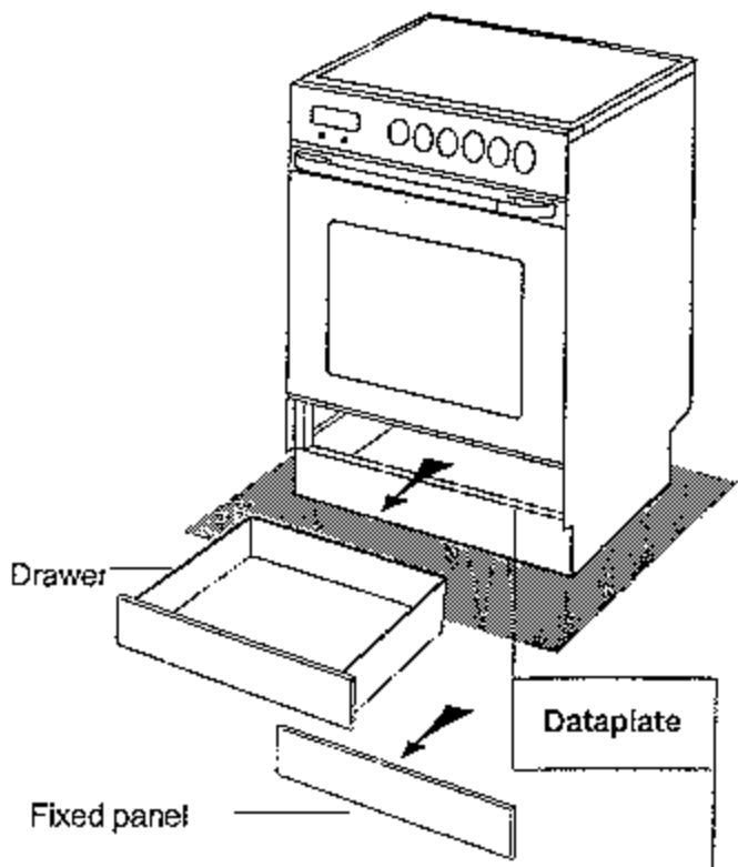
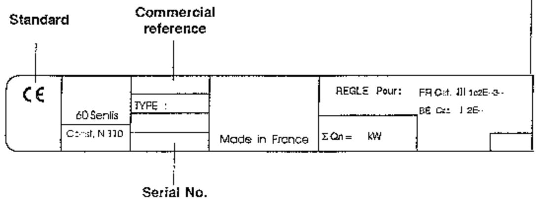
9. DATAPLATE
The information on the dataplate will be necessary in the event of breakdown and if you want to order parts from the After-Sales Service.
Remove the drawer or the fixed panel to see the dataplate. To do so, proceed as follows:
Model with drawer
Pull the drawer as far out as possible
- Raise the drawer to clear the stop
Remove the drawer entirely
Model with fixed panel
Pull the panel attached by clips upward
Clear the panel upward
1. INSTALLATION SAFETY INSTRUCTIONS
If a defect is observed when the equipment is unpacked, it must be put back in its original packaging before being returned to the manufacturer.
Before installation, ensure that local distribution conditions (type and pressure of gas) and the adjustment of the appliance are compatible.
This cooker must only be installed on properly ventilated premises. The adjustment conditions concerning the cooker appear on the dataplate.
This cooker is not connected to a combustion product evacuation system. It must be installed and connected in accordance with the current installation regulations. Pay particular attention to the provisions applicable in terms of ventilation.
The required new air flow-rate is 28 m3/h.
" Walls adjacent to the cooker must either be of heatresisting material or lined with such material. See chapter 21.
- Electrical connection
The cookers are supplied exclusively for 230 V AC. Check the following:
that the installation power is sufficient
that the supply lines are in good condition
- that the wire diameter is in conformity with the installation rules
that the permanent installation includes a device having cut-off contact on all poles with a contact opening distance of 3 mm at the least.
- Connection to gas system
Check:
that the flow-rate of the meter and the diameter of the pipes are sufficient to feed the installation equipment together
that the unions are tight.
Install a visible and accessible stop valve
If a flexible pipe is used, the entire length must be open to inspection and it must not run behind the cooker
We advise you to replace the flexible pipe slightly before the expiration date indicated on it
For France
Installation and maintenance must be carried out by a professional qualified in accordance with the regulations and the current state of the art rules in particular:
August 2, 1977 ruling - technical and safety rules applicable to gas-fired and liquefied hydrocarbon installations in housing and their annexes
DTU P45-204 Standards- gas installations
Department sanitary regulation
For cookers connected to the electric system: NF C 15-100 Standard: low voltage electrical installations.
For Belgium
The installation and maintenance of the equipment shall be carried out by a professional qualified in accordance with the regulations and the current state of the art rules in particular: NBND 51003.
For equipment connected to the electrical network: NBN Standard.
Our responsibility is not engaged if accidents or incidents are caused by failure to connect the equipment to ground, or defective ground installation.
2.1 Positioning of cooker
Freestanding cooker
The cooker should be installed as shown in the figures opposite and the minimum distances between the cooker and the adjacent walls of any cabinets must be allowed for as indicated in the drawings.
The cooker has 4 feet for adjusting the height and level for alignment (with cover closed) with the counter tops of adjacent cabinets
If the cooker is placed next to a cabinet, align the edge of the hob with the counter surface of the adjacent cabinet.
2.2 Electrical connection
-
This cooker has a flexible cable with a plug for connection to a power outlet
The cooker must be connected to a 230 VAC supply
Check the following: -
sufficient installation power rating
supply lines in good condition
wire diameter in conformity with current installation rules
permanent user installation includes all-pole cutoff device with contact opening distance of at least 3 mm - fuse rating: 10 amperes
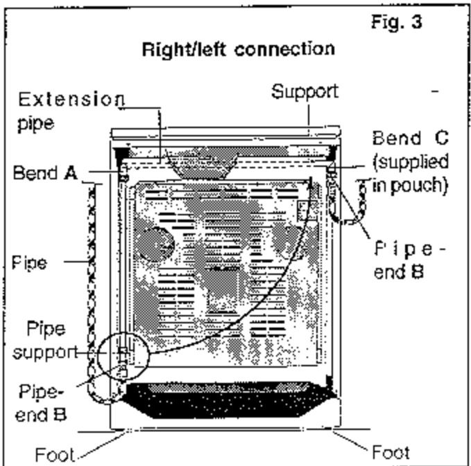
2.3 Gas connection
The cooker can be connected on the right or on the left. Choose the side closest to the gas supply so that the flexible pipe does not run behind the cooker and is not in contact with the rear wall. It must be open to inspection over its entire length.
Changing gas inlet sides
- Unscrew Pipe-end B, the pipe support and the extension pipe
- Unscrew slightly bend A and turn it to the right. then tighten it again
- Attach the support on the right of the cooker, assemble Pipe-end B. Bend C and the extension pipe
- Engage the extension pipe in the support and screw it on to Bend C.
Connect the flexible pipe
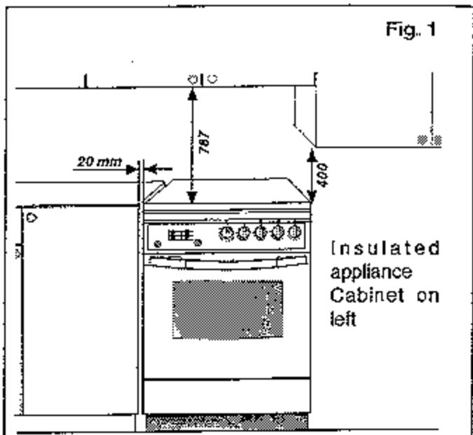
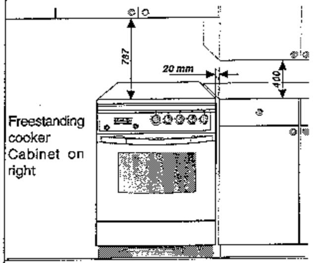
Fig. 2
2.3.1 Choice of pipe
a) For gas distributed by piping
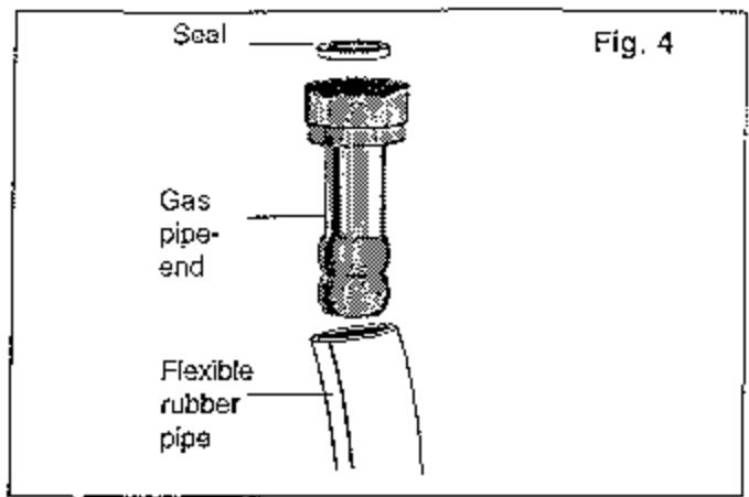
For France only
Use a flexible rubber pipe with a maximum length of 1.50 m and an inside diameter of 15 mm. mounted with its gas fitting (Fig. 4).
Fush it home sufficiently and attach it with a collar.
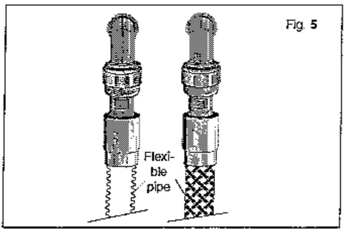
France and Belgium
Use a flexible pipe (with mechanical pipe-end fittings). maximum length 1.50 m (Fig. 5)
We advise the use of a standardized flexible pipe having a minimum length of 1 m and a length chosen according to the position of the stop valve
- Connect one pipe-end of the flexible pipe to the stop valve then, before placing the cooker between the cabinets, connect the other pipe-end to the extension pipe
Position the cooker, ensuring that the loop formed by the flexible pipe is in the sanitary space of the adjacent cabinet
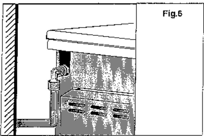
Or a rigid pipe with a nut (Fig. 6)
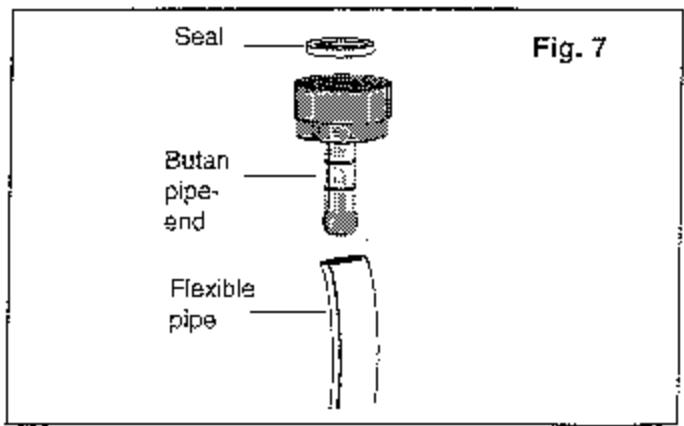
b) For butane-propane cylinders or tanks
Use a flexible rubber pipe no longer than 1.50 m with 6 mm inside diameter mounted with the special butane pipe-end fitting (Fig. 7).
2.3.2 When buying a pipe
In France
- Flexible rubber pipe: must be marked NF GAZ
Flexible pipe: must be in compliance with NF D 36 121 or NF D 36 103 or NF D 36 107 Standard
In Belgium
- Flexible rubber pipe: must be compliant with the current standard
Flexible pipe: must be compliant with Specification ARGB 03/80
Rigid pipe: must be in conformity with Standard NBND 51003
3. MAINTENANCE
For safety's sake, before disassembly, disconnect the electrical supply of the cooker
3.1 Disassembly and assembly of hob cover
Remove the hob cover entirely then pull it towards you while raising it, to remove.
For assembly incline the cover and engage the hinge parts in their recesses. Raise the cover.
3.2 Replacing the oven lamp
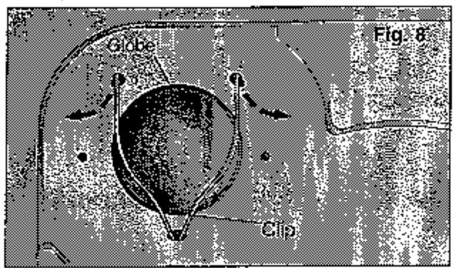
Important: For safety's sake, make sure the cooker is disconnected from the power input. This 40 W lamp with an E 27 (230 V) screw base is a special heat-resisting lamp for high temperatures. It can be supplied on request by the Spare Parts Department.
If the oven is a smoothed enamel oven
- Unclip, one by one, the arms of the clip to remove the globe (Fig. 8)
- Replace the bulb
For assembly:
Put the globe back, hold it in place and insert the clip pins one by one
If your oven is a catalytic enamel oven (rough appearance)
- Remove the bottom plate by pulling towards you
- Raise the sides and tilt them into the oven
Then remove the back wall
One by one, unclip the arms of the clip to remove the globe (Fig. 8)
Replace the bulb
For assembly:
- Replace the globe, holding it and insert the arms of the clip back, one by one
- Push the back wall up and lower it so that the tab of the wall enters the runner of the oven
- Push the sides up entirely and hold them in place
- Slide them down so that the runner in the oven and side coincide. Then release
- Put the bottom plate back
4. CHANGING GAS
In Belgium, the cooker is only adaptable by the manufacturer.
On purchase, the cooker is designed to operate on natural gas. To use butane or propane, apouch containing injectors/pipe-end fittings is supplied. To use propane with air or butane with air or any other type of gas, contact your After-Sales Service.
To change gas, it is necessary to:
- change the injectors (hob, grill, oven)
- change the air settings (hob, grill oven)
- change the low flow-rate settings (hob, oven)
check the connection method.
4.1 Change of hob injectors
- Remove the cover
- Remove the hob grills, the burner caps and inserts. The rings are held in place by clips. Grasp the burners at the base and pull them vertically upward so as not to force against the ignition spark generators
- Undo the 2 rear screws of the hob using a Philips-head screwdriver
" Lift slightly and push the top of the hob back to remove it
Loosen the screws of the air sleeves in order to push them back and gain access to the injectors - Unscrew the injectors with a 9 mm open-end wrench and install in their place the injectors corresponding to the new gas (see Table No.1).
Table No.1
| FRANCE only | FRANCE and BELGIUM | |||||||||
| BURNERS | Propane air Butane air G130 | Natural gas G20 - G25 | Butane - Propane G30 - G31 | Power KW | ||||||
| Liters/hour | inj. mark | Liters/hour | inj. mark | g/h | inj. mark | Nominal | Low | |||
| AP 8 mbar | AB 8 mbar | Group "H" 20 mbar | Group "L" 25 mbar | 28-30 mbar 37 mbar | ||||||
| FAST FRONT | 455 | 470 | 280 | 311 | 361 | 131 | 237 | 88 | 3,26 | 0,65 |
| FAST REAR | 366 | 377 | 230 | 250 | 290 | 115 | 190 | 78 | 2,62 | 0,55 |
| SEMI-FAST | 244 | 252 | 175 | 167 | 194 | 95 | 127 | 65 | 1,75 | 0,37 |
| GRILL | 334 | 344 | 210 | 228 | 265 | 118 | 174 | 79 | 2,60 | - |
| OVEN | 585 | 604 | 320 | 399 | 464 | 145 | 305 | 96 | 4,19 | - |
Important
When changing gas to butane or propane you must affix the corresponding sticker (G30), to be found in the injector pouch on the cooker
For France only
When changing gas to butane and air or propane and air affix the sticker (G 130).
4.2 Change of grill injector
- Plug the orifice of the air/gas mixture with a piece of adhesive tape to prevent the injector from falling in (Fig. 9)
Replace the grill injector in accordance with Table No.1 - When the new injector is in place, remove the adhesive tape
4.3 Changing the oven injector
- Open the oven door
- Remove the bottom plate by pulling it towards you
- Remove the clips retaining the oven burner
- Replace the injector on the back wall of the cavity with a 10 mm tubular wrench in accordance with Table No. 1
4.4 Air adjustment of hob burner
Adjustment is obtained by means of the air sleeve.
Adjust air inlet dimension C of the air/gas mixer using a screwdriver, as indicated in Table No. 2, depending on the type of gas and burner (Fig. 10).
After adjustment lock the sleeve by tightening the screw.
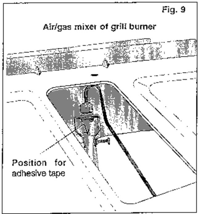
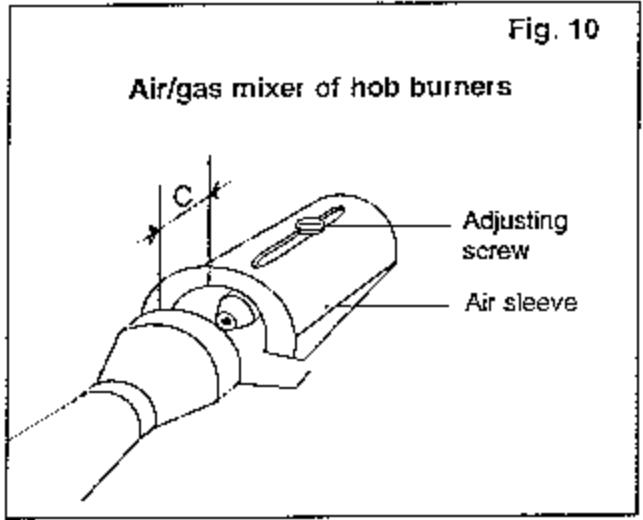
Table No2
| FRANCE only | FRANCE and BELGIUM | |||||
| Type of burner | Propane air | Butane Air | Natural gas Group H | Natural gas Group L | Butane | Propane |
| Dimension C in mm | ||||||
| Semi-fast | 0 to 0.5 | 1 to 1.5 | 20 | 7 | ||
| Rear fast 2.62 kW | 2.5 | 1 to 1.5 | 20 | 5 | ||
| Front fast 3.26 kW | 4 to 4.5 | 2 to 2.5 | 20 | 2 | ||
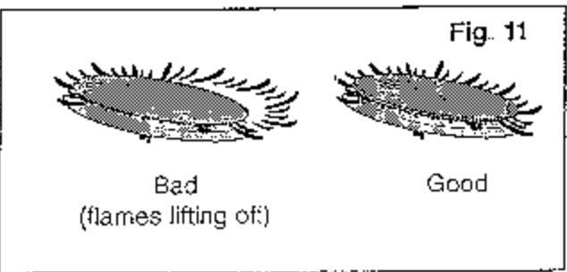
When you check operation after making all the modifications, if the flames are yellow, increase Dimension C of the burner concerned. Otherwise if the flames tend to lift off their source decrease this dimension (Fig. 11).
4.5 Air adjustment of grill and oven burner
- Undo the adjusting screw of the air/gas mixture as far as the inside wall of the tube (Fig. 12)
Make a mark on the screw head
Tighten according to the number of turns indicated in Table No. 3
Check:
Oven burner
- Turn on the oven burner. If the flames are yellow, loosen the adjusting screw slightly. Otherwise, if the flames lift away, tighten the adjusting screw slightly (Fig. 13).
Grill burner
Check that the grill flames are short and blue, that they are stable, and cover all of the metal grill which reddens after a few seconds.
After adjustment, lock the screws with the lock nut (fig. 12)
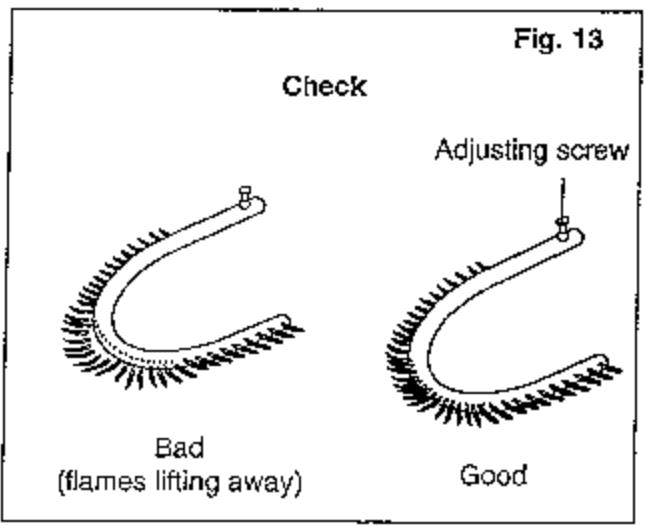
Table No. 3
| FRANCE only | FRANCE and BELGIUM | |||||
| Type of burner | propane air | butane air | Natural gas Group H | Natural gas Group L | Butane | Propane |
| Number of turns of screw | ||||||
| Oven | 8 à 9 | 10 | 0 | 6 | ||
| Grill | 10 | 6 | 5 | 10 | ||
4.6 Adjusting low flow-rates of hob burners
To adjust the low flow-rates:
Install the burners
- Turn the burners to the maximum setting
Turn the control knobs to minimum
- Remove all the control knobs using a cloth and a pair of pliers
The reduced flow-rate adjusting screw of each burner is located on the valve body (Fig. 14)
- Operate in accordance with the indications of Table No. 4
Check:
Turn the control knobs several times from maximum to minimum position to check the stability of the flames. If a burner goes out, undo slightly the adjusting screw.
Assemble the control knobs again
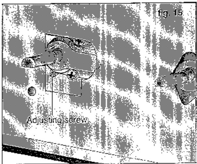
4.7 Adjusting the low flow-rate of the oven burner
To adjust the low flow-rate of the oven burner, adjust screw (Fig. 15) in accordance with Table No. 5.
After adjustment check that the flames burn steadily.
Turn the oven burner on in the maximum position and allow to heat, with the door closed for approximately 15 minutes
Turn the oven control from maximum to minimum
- Open the door normally and check for the presence of flames
Turn the control from maximum to minimum several times
Open and close the door when the oven is turned to minimum
If the burner goes out, unscrew the adjusting screw very slightly
Assemble the oven burner
Put the bottom plate back
Table No. 4
| Butane | Natural gas | Butane air Propane air |
| Screw the screw entire home turning it clockwise | Screw or unscrew the screw until a very short flame is obtained | Screw or unscrew the screw until a very short flame is obtained |
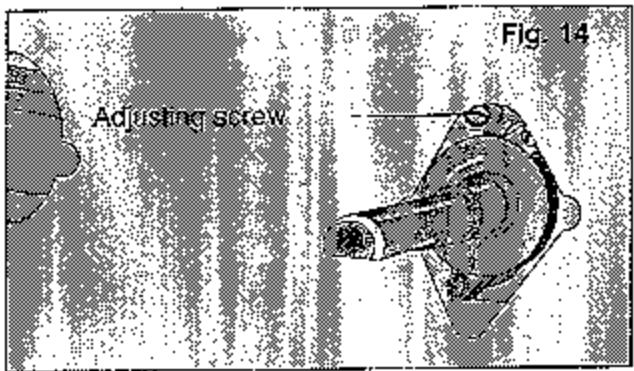
Table No. 5
| Butane | Natural gas | Butane Air Propane Air |
| Tighten the screw fully. | Tighten the screw fully then undo by 11/2 to 1¾ turns. | Tighten the screw fully then undo by 1½ to 1¾ turns. |