
BELLAGIO - Moto MOTO GUZZI - Notice d'utilisation et mode d'emploi gratuit
Retrouvez gratuitement la notice de l'appareil BELLAGIO MOTO GUZZI au format PDF.

| Type de produit | Moto de style cruiser |
| Caractéristiques techniques principales | Moteur V-twin, 744 cm³, refroidissement par air |
| Puissance | 50 ch à 6 800 tr/min |
| Couple | 62 Nm à 5 000 tr/min |
| Transmission | Boîte de vitesses à 5 rapports |
| Dimensions approximatives | Longueur : 2 100 mm, Largeur : 800 mm, Hauteur : 1 100 mm |
| Poids | 210 kg (à sec) |
| Capacité du réservoir | 15 litres |
| Type de suspension avant | Fourche télescopique de 40 mm |
| Type de suspension arrière | Amortisseur unique réglable |
| Freins avant | Disque simple de 320 mm avec étrier à 4 pistons |
| Freins arrière | Disque simple de 260 mm avec étrier à 2 pistons |
| Utilisation | Conduite en ville et sur route |
| Entretien et nettoyage | Vérification régulière de l'huile moteur, nettoyage de la chaîne, contrôle des freins |
| Pièces détachées et réparabilité | Disponibilité des pièces chez les concessionnaires et revendeurs agréés |
| Sécurité | Équipement de sécurité recommandé : casque, gants, vêtements renforcés |
| Informations générales | Modèle apprécié pour son design rétro et son confort de conduite |
FOIRE AUX QUESTIONS - BELLAGIO MOTO GUZZI
Questions des utilisateurs sur BELLAGIO MOTO GUZZI
0 question sur cet appareil. Repondez a celles que vous connaissez ou posez la votre.
Poser une nouvelle question sur cet appareil
Téléchargez la notice de votre Moto au format PDF gratuitement ! Retrouvez votre notice BELLAGIO - MOTO GUZZI et reprennez votre appareil électronique en main. Sur cette page sont publiés tous les documents nécessaires à l'utilisation de votre appareil BELLAGIO de la marque MOTO GUZZI.
MODE D'EMPLOI BELLAGIO MOTO GUZZI
MOTO GUZZI DESEA AGRADECERLE
por haber elegido uno de sus produits. Hemos preparado este manual para permitirleajsrear todas sus calidades. Le aconsejamos que lea todo su contenido antes de conducir por primera vez. Contiene informacion, consejos y advertencias para el uso de su vehiculo; asimismo, descubriraracteristicas, detalles y soluiones que lo convenceran de lo acertado de su eleccion. Estamos seguros de que teniendo todo thiso en cuesta, le的结果arfacil concer su nuevo vehiculo, el cui podra disfurar por mucho tiempo con total satisfacion. La presente publicacion es parte integrante del vehiculo y en caso de vendlerlo debserentagado al nuevo propietario.
MOTO GUZZI WOULD LIKE TO THANK YOU
for choosing one of its products. We have drawn up this booklet to provide a comprehensive overview of your vehicle's quality features. Please read it carefully before riding the vehicle for the first time. It contains information, tips and precautions for using your vehicle. It also describes features, details and devices to assure you that you have made the right choice. We believe that if you follow our suggestions, you will soon get to know your new vehicle well and will use it for a long time at full satisfaction. This booklet is an integral part of the vehicle, and should the vehicle be sold, it must be transferred to the new owner.

Bellagio
Las instruetiones de este manual han sido preparadas principalmente para suministrar una guía simple y clara para el uso; se indicate还可以 las operaciones de mantenimiento Basics y los controlles periodicos que se deben realizar en los Concesionarios o Talleres autorizados Moto Guzzi. Además, el manual contiene las instruetiones para que pueda realizar algunos reparaciones simples. Las operaciones que no se describen explicitly en esta publicación requieren la disponibility de herramrientas especialas y/o de conocimientos tíncicosesionos. para su ejaculation recomendamos dirigirse a los Concesionarios o Talleres autorizados Moto Guzzi.
The instructions in this booklet are intended to provide a clear, simple guide to using your vehicle; it also describes routine maintenance procedures and regular checks that should be carried out on the vehicle at an authorised Moto Guzzi Dealer or Workshop. The booklet also contains instructions for simple repairs. Any operations not specifically described in this booklet require the use of special tools and/or particular technical knowledge: for these operations, please take your vehicle to an authorised Moto Guzzi Dealer or Workshop.

Seguridad de las personas
El no-cumplimiento total o parcial de estas prescrip-. ciones puedeistarpeligrogravepara la inco-. lumdidadde laspersonas.
Personal safety
Failure to completely observe these instructions will result in serious risk of personal injury.

Salvaguardia del ambiente
Indica el comportamiento correcto para que el uso del vehiculo no cause ningún daño a la naturaleza.
Safeguarding the environment
Sections marked with this symbol indicate the correct use of the vehicle to prevent damaging the environment.

Integridad del vehiculo
El no-cumplimiento total o parcial de estas prescrip- cionescomeda elpeligro de serios daños al vehiculo e incluso la caducidad de la garantía.
Vehicle intactness
The incomplete or non-observance of these regulations leads to the risk of serious damage to the vehicle and sometimes even the invalidity of the guarantee.
Las señales indicadas previamente son de gran importancia. Sirven para evidiar las partes del manual que requirecen de más atencion. Como se puede observar, cada senal está compuesta por un simbolo grfico differente, para facilitar y agilizar la búsqueda de los temas en las diversas areas. Antes deponer en marcha el motor, leer attentamente este manual, especiallynte le apartado "CONDUCCION SEGURA". Su seguidad y la de los demas no depende solamente de la rapidez de sus reflejos y agilidad, sino también del conocimiento del vehiculo, de su eficiencia y del conocimiento de las reglasfundamentales para la CONDUCCION SEGURA. Por lo tanto, le recomendamos familiarizarse con el vehiculo lo suficiente como para circular por la carretera con total control y seguidad. IMPORTANTE Estemanual se debe considerar como parte integrante del vehiculo y debe acomaiparrio en caso de
The recommendations above are very important. They are used to highlight those parts of the booklet that should be read with particular care. As you can see, each sign consists of a different graphic symbol, making it quick and easy to locate the various topics. Before starting the engine, read this booklet carefully, particularly the "SAFE RIDING" section. Your safety as well as other's does not only depend on the quickness of your reflexes and agility, but also on how well you know your vehicle, its efficiency and your knowledge of the rules for SAFE RIDING. For your safety, get to know your vehicle well so as to safely ride and master it in road traffic IMPORTANT This booklet is an integral part of the vehicle, and should the vehicle be sold, it must be transferred to the new owner.
venta.
Bellagio


INDICE
INDEX
INDICE
Cap. 01 Normas generales
Cap. 02 . Vehiculo
Cap. 03 El uso
Cap. 04 El mantenimiento
Cap. 05 . Datos&Tecnicos
Cap. 06 El mantenimiento programado
Cap. 07 . Preparaciones especiales
INDEX
Chap. 01 General rules
Chap. 02 Vehicle
Chap. 03 Use
Chap. 04 Maintenance
Chap. 05 Technical data
Chap. 06 Programmed maintenance
Chap. 07 Special fittings
Bellagio


Cap. 01
Normas generales
Chap. 01
General rules
Introduccion
NOTA
EL TIEMPO PREVISTO PARA REALIZAR LAS OPERaciones DE MANTENIMIENTO, DEBE SER REDUCIDO A LA MITAD SI EL VEHICULO SE UTILIZA EN ZONAS LLUVIOSAS, POLVORIENTAS, EN RECORRIDOS ACCIDENTADOS O EN CONDUCCION DEPORTIVA.
Foreword
NOTE
CARRY OUT MAINTENANCE OPERATIONS AT HALF THE INTERVALS SHOWN IF THE VEHICLE IS USED IN WET OR DUSTY AREAS, OFF ROAD OR FOR SPORTING APPLICATIONS.
Monóxido de carbono
Si esnecessaryhacerfuncionarelmotorpara poderefctuargunaoperacion,aseguararse de quethisocurraen un espacio abierto o en un ambienteventilado de manera adecuada.Nunca hacerfuncionarlemotor en espacios cerrados.Si se trabajo en un espacio cerrado,utilizarunistema de evacuationde loshumos deescape.
ATENCLON

LOS HUMOS DE ESCAPE CONTIENENOXIDO DE CARBONO, UN GAS VENENO-SO QUE PUEDE PROVOCAR LA PERDIDA DE CONOCIMIENTO E INCLULO LA MUERTE.
Carbon monoxide
If you need to keep the engine running in order to perform a procedure, please ensure that you do so in an open or very well ventilated area. Never let the engine run in an enclosed area. If you do work in an enclosed area, make sure to use a smoke-extraction system.
CAUTION

EXHAUST EMISSIONS CONTAIN CARBON MONOXIDE, A POISONOUS GAS WHICH CAN CAUSE LOSS OF CONSCIOUSNESS AND EVEN DEATH.
Combustible
Fuel
ATENCLON


EL COMBUSTIBLE UTILIZADO PARA LA PROPULSION DE LOS MOTORES DE EXPLOSION ES EXTREMADAMENTE INFLAMMBLE Y PUEDE RESULTAR EXPLOSIVO EN DETERMINADAS CONDICIONES. CONVIENE REALIZAR EL REABASTECIMIENTO Y LAS OPERaciones DE MANTENIMIENTO EN UNA ZONA VENTILADA Y CON EL MOTOR APAGADO. NO FUMAR DURANTE EL REABASTECIMIENTO NI CERCA DE LOS VAPORES DE COMBUSTIBLE, Y EVITAR ABSOLUTAMENTE EL CONTACTO CON LLAMAS DESNU-DAS, CHISPAS Y CUALQUIER OTRA FUENTE QUE PODRIA HACER QUE EL COMBUSTIBLE SE ENCIENDA O EXPLOTE.
NO ARROJAR EL COMBUSTIBLE AL MEDIO AMBIENTE.
MANTENER FUERA DEL ALCANCE DE LOS NINOS.
CAUTION


FUEL USED TO POWER INTERNAL COMBUSTION ENGINES IS HIGHLY FLAMMABLE AND CAN BECOME EXPLOSIVE UNDER SPECIFIC CONDITIONS. IT IS THEREFORE RECOMMENDED TO CARRY OUT REFUELLING AND MAINTENANCE PROCEDURES IN A VENTILATED AREA WITH THE ENGINE SWITCHED OFF. DO NOT SMOKE DURING REFUELLING AND NEAR FUEL VAPOURS, AVOIDING ANY CONTACT WITH NAKED FLAMES, SPARKS OR OTHER SOURCES WHICH MAY CAUSE THEM TO IGNITE OR EXPLODE.
DO NOT DISPERSE FUEL IN THE ENVIRONMENT.
KEEP OUT OF THE REACH OF CHILDREN

LA CAIDA O LA EXCESIVA INCLINACION

VEHICLE FALL OR EXCESSIVE INCLINA
DEL VEHICULO PUEDEN PRODUCIR DE-TION CAN CAUSE FUEL OUTFLOW. RRAMES DE COMBUSTIBLE.
Componentes calientes
El motor y los componentes de la instalación de escape alcanzan altas temperatas y permanecen calientes durante un cierto periodo, incluo afterwards de apagar el motor. Para Manipular这些东西 componentes, utilizar guantes aislantes o esperar hasta que el motor y la instalación de escape se hayan enfiado.
Hot components
The engine and the exhaust system components get very hot and remain in this condition for a certain time interval after the engine has been switched off. Before handling these components, make sure that you are wearing insulating gloves or wait until the engine and the exhaust system have cooled down.
Puesta en marcha y Conduccion
ATENCLON
SI DURANTE LA CONDUCCION, EN EL TABLERIO SE ENCIENDE EL TESTIGO DE RESERVRA DE COMBUSTIBLE, SIGNIFICIA QUE COMIENZA A UTILITIZE LA REServa.
REPONER COMBUSTIBLE LO ANTES POSIBLE.
Start off and Riding
CAUTION
IF THE LOW FUEL WARNING LIGHT ON THE INSTRUMENT PANEL TURNS ON WHILE RIDING, THIS MEANS THE RESERVE IS BEING USED.
REFUEL AS SOON AS POSSIBLE.
Testigos

Warning lights

SI EL TESTIGO LED ALARMA Y EL ICO- NO DE DIAGNOSTICO " SERVICE" SE ENCIENDEN DURANTE EL FUNCIONAMIENTO NORMAL DEL MOTOR, SIGNIFICA QUE LA CENTRALITA ELECTRONICA HA DETECTADO ALGUNA ANOMALIA.
EN MUCHOS CASOS EL MOTOR CONTINUÁ FUNCIONANDO CON RENDIMIENTO LIMITADO; DIRIGIRSE INMEDIATAMENTE A UN CONCESIONARIO OFICIAL Moto Guzzi.
DESPUÉS DE LOS PRIMEROS 1.000 KM (625 MILLAS) Y SUCESIVAMENTE CADA 10.000 KM (6.250 MILLAS), EN LA PANTALLA DERECHA SE VISUALIZA EL ICONO "SERVICE".
EN ESTE CASO, DIRIGIRSE A UN CONCESSIONARIO OFICIAL Moto Guzzi, PARA REALIZAR LAS INTERVENTIONES PREVISTAS EN LA FICHA DE MANTENIMIENTO PERIODICO.

SI EL TESTIGO DE ALARMA Y EL ICONO EN LA PANTALLA PRESION ACEITE MOTOR PERMANECEN ENCENDIDOS, O SE ENCIENDEN DURANTE EL FUNCIONAMIENTO NORMAL DEL MOTOR, SIGNIFICIA QUE LA PRESION DEL ACEITE EN EL CIRCUito ES INSUFICIENTE.

IF THE ALARM LED WARNING LIGHT AND THE " SERVICE" DIAGNOSIS ICON TURN ON DURING REGULAR ENGINE OPERATION, IT MEANS THAT THE ELECTRONIC CONTROL UNIT HAS DETECTED SOME FAILURE.
IN MANY CASES THE ENGINE CONTINUES TO WORK WITH LIMITED PERFORMANCE; IMMEDIATELY CONTACT AN OFFICIAL Moto Guzzi DEALER.
AFTER THE FIRST 1000 KM (625 MILES) AND THEN EVERY 10000 KM (6250 MILES), THE "SERVICE" ICON APPEARS ON THE RIGHT DISPLAY.
IF THIS OCCURS TAKE YOUR vehicle TO AN OFFICIAL Moto Guzzi DEALER TO CARRY OUT THE MAINTENANCE OPERATIONS SPECIFIED IN THE PERIODIC MAINTENANCE CHART.

IF THE ALARM WARNING LIGHT AND THE ICON ON THE ENGINE OIL PRESSURE DISPLAY REMAINS ON, OR IF IT TURNS ON DURING ENGINE REGULAR OPERATION, IT MEANS THAT THE OIL PRESSURE IN THE CIRCUIT IS TOO LOW.

IN THIS CASE, CHECK THE ENGINE OIL LEVEL AND IF IT IS NOT CORRECT, STOP THE ENGINE IMMEDIATELY AND
EN Este CASO CONTROLAR EL NIVEL DE ACEITE DEL MOTOR Y SI NO FUERA EL CORRECTO, DETENERLO INMEDIATEYRESTABLECER EL NIVEL.
DIRIGIRSE A UN Concessionario Oficial Moto Guzzi PARA QUE CONTROLLE LA INSTALLACION.
TOP-UP.
CONTACT AN OFFICIAL Moto Guzzi Dealer TO CHECK THE CIRCUIT.
Aceite motor y aceite cambio usados
ATENCLON


EN CASO DE INTERVENCIONES DE MANTENIMIENTO, SE RECOMIENDA EL USO DE GUANTES DE LATEX. EL ACEITE MOTOR O DEL CAMBIO DE VELOCIDADES PUEDE PROVOCAR SERIOS DANOS EN LA PIEL SI SE MANIPULA POR Mucho TIEMPO Y COTIDIANAMENTE. SE RECOMIENDA LAVAR CUIDADOSAMENTE LAS MANOS DESPUES DE HABERLO MANIPULADO. ENTREGARLO O HACERLO RETIRAR POR LA EMPRESA DE RECUPERACION DE ACEITES USADOS MAS CERCANA O POR EL PROVEEDOR. EN CASO DE INTERVENCIONES DE MANTENIMIENTO, SE RECOMIENDA EL USO DE GUANTES DE LATEX.
Used engine oil and gearbox oil
CAUTION


IT IS ADVISIBLE TO WEAR LATEX GLOVES WHEN SERVICING THE VEHICLE. THE ENGINE OR TRANSMISSION OIL MAY CAUSE SERIOUS INJURIES TO THE SKIN IF HANDLED FOR PROLONGED PERIODS OF TIME AND ON A REGULAR BASIS. WASH YOUR HANDS THOROUGHLY AFTER HANDLING IT. HAND THE OIL OVER TO OR HAVE IT COLLECTED BY THE NEAREST USED OIL RECYCLING COMPANY OR THE SUPPLIER. IT IS ADVISIBLE TO WEAR LATEX GLOVES WHEN SERVICING THE VEHICLE.
DO NOT DISPOSE OF OIL IN THE ENVIR
NO ARROJAR EL ACEITE AL MEDIO AMBIENTE
MANTENER FUERA DEL ALCANCE DE LOS NINOS.
ONMENT
KEEP OUT OF THE REACH OF CHILDREN
Liquido frenos y embrague
Liquido frenos y embrague

LOS LÍQUIDOS DE FRENOS Y DEL EMBRAGE PUEDEN DANAR LAS SUPERFICIES PINTADAS, DE PLASTICO O DE GOMA. CUANDO SE REALIZA EL MANTENIMIENTO DEL SISTEMA DE FRENOS O DEL EMBRAGE, PROTEGER ESTOS COMPONENTES CON UN PANO LIMPIO. UTILizar SIempre ANTIPARRAS DE PROTECCION PARA REALizar EL MANTENIMIENTO DE ESTOS SISTemas. EL LÍQUIDO DE FRENOS Y DEL EMBRAGE SON SUMAMENTE DANINOS PARA LOS OJOS. EN CASO DE CONTACTO ACCIDENTAL CON LOS OJOS, ENJUAGAR INMEDIATAMENTE CON ABUNDANTE AGUA FRIY A LIMPIA, Y CONSULTAR INMEDIATAMENTE A UN MEDICO.
MANTENER FUERA DEL ALCANCE DE LOS NINOS.
Brake and clutch fluid
Brake and clutch fluid

THE BRAKE AND CLUTCH FLUIDS CAN DAMAGE THE PLASTIC OR RUBBER PAINTED SURFACES. WHEN SERVICING THE BRAKING SYSTEM OR THE CLUTCH SYSTEM PROTECT THESE COMPONENTS WITH A CLEAN CLOTH. ALWAYS WEAR PROTECTIVE GOGGLES WHEN SERVICING THE SYSTEMS. BRAKE AND CLUTCH FLUIDS ARE EXTREMELY HARMFUL FOR YOUR EYES. IN THE EVENT OF ACCIDENTAL CONTACT WITH THE EYES, RINSE THEM IMMEDIATELY WITH ABUNDANT COLD, CLEAN WATER AND SEEK MEDICAL ADVICE.
KEEP OUT OF THE REACH OF CHILDREN
Electrolito y gas hidrógeno
Battery hydrogen gas and
de la bateria
ATENCIón

EL ELECTROLITO DE LA BATERIA ES TOXICO, CAUSTICO Y EN CONTACTO CON LA EPIDERMIS PUEDE CAUSAR QUEMADURAS, YA QUE CONTIENE ACIDO SULFUFIRICO. USAR GUANTES ADHERENTES E INDUMENTARIA DE PROTECION AL MANIPULAR EL ELECTROLITO DE LA BATERIA. SI EL LIQUIDO ELECTROLITICO ENTRA EN CONTACTO CON LA PIEL, LAVAR CON ABUNDANTE AGUA FRIA. ES MUY IMPORTANTE PROTEGER LOS OJOS, YA QUE INCLUso UNA PEQUENISIMA CANTIDAD DE ACIDO DE LA BATERIA PUEDE PRODUCIR CEGUERA. SI EL LIQUIDO ENTRA EN CONTACTO CON LOS OJOS, LAVAR CON ABUNDANTE AGUA DURANTE QUINCE MINUTOS, LUEGO DIRIGIRSE IMEDIATAMENTE A UN OCULISTA. SI SE INGIERE LIQUIDO ACCIDENTALMENTE, BEBER ABUNDANTE CANTIDAD DE AGUA O LECHE, CONTINUAR CON LECHE DE MAGNESIA O ACEITE VEGETAL, LUEGO DIRIGIRSE INMEDIATAMENTE A UN MEDICO. LA BATERIA EMANA GASES EXPLOSIVOS: CONVIENE MANTENERLA ALEJADA DE LLAMAS, CHISPAS, CIGARRILLOS Y CUALQUIER OTRA FUENTE DE CALOR. PREVER UNA AI-REACIOn ADECUADA AL REALIZAR EL
electrolyte
CAUTION

THE BATTERY ELECTROLYTE IS TOXIC, CORROSIVE AND AS IT CONTAINS SULPHURIC ACID, IT CAN CAUSE BURNS WHEN IN CONTACT WITH THE SKIN. WHEN HANDLING BATTERY ELECTROLYTE, WEAR TIGHT-FITTING GLOVES AND PROTECTIVE APPAREL. IF THE FLUID GETS INTO CONTACT WITH THE SKIN, RINSE WELL WITH ABUNDANT FRESH WATER. IT IS EXTREMELY IMPORANT TO PROTECT THE EYES BECAUSE EVEN A SMALL QUANTITY OF BATTERY ACID CAN CAUSE BLINDNESS. IF THE FLUID GETS INTO CONTACT WITH THE EYES, WASH WITH ABUNDANT WATER FOR FIFTEEN MINUTES AND CONSULT AN EYE SPECIALIST IMMEDIATELY. IF THE FLUID IS ACCIDENTALLY SWALLOWED, DRINK LARGE QUANTITIES OF WATER OR MILK, FOLLOWED BY MILK OF MAGNESIA OR VEGETABLE OIL AND SEEK MEDICAL ADVICE IMMEDIATELY. THE BATTERY RE-LEASES EXPLOSIVE GASES; KEEP IT AWAY FROM FLAMES, SPARKS, CIGARETTES OR ANY OTHER HEAT SOURCES. ENSURE ADEQUATE VENTILATION WHEN SERVICING OR RECHARGING THE BATTERY.
MANTENIMIENTO O LA RECARGA DE LA BATERIA.
MANTENER FUERA DEL ALCANCE DE LOS NINOS.
EL LIQUIDO DE LA BATERIA ES CORROSIVO. NO DERRAMARLO NI DESPARRAMARLO, ESPECIALMENTE SOBRE LAS PARTES DE PLASTICO. ASEGURARSE DE QUE EL ACIDO ELECTROLITICO SEA EL ESPECIFICO PARA LA BATERIA QUE SE DESEA ACTIVAR.
KEEP OUT OF THE REACH OF CHILDREN
BATTERY LIQUID IS CORROSIVE. DO NOT POUR IT OR SPILL IT, PARTICULARLY ON PLASTIC COMPONENTS. ENSURE THAT THE ELECTROLYTIC ACID IS COMPATIBLE WITH THE BATTERY TO BE ACTIVATED.
Sopporte

ANTES DE PARTIR, ASEGURARSE QUE EL CABALLETE HAYA REGRESADO COMPLETAMENTA A SU POSICION.
NO CARGAR SOBRE EL CABALLETE LATERAL EL PESO DEL CONDUCTOR NI EL DEL PASAJERO.
Stand

BEFORE RIDING, MAKE SURE THE STAND HAS BEEN COMPLETELY RETRACTED TO ITS POSITION.
DO NOT REST THE RIDER OR PASSENGER WEIGHT ON THE SIDE STAND.
Comunicación de los defectos que influyen en lacurity
PRECAUCIONES E INFORMACION GENERAL
Al realizar la reparacion, el desmontaje y el
Reporting of defects that affect safety
GENERAL PRECAUTIONS AND INFORMATION
When repairing, dismantling and reassembling the vehicle follow the recommenda
montaje del vehiculo, se deben respetar con tions reported below carefully.
exactitud las siguientes recomendaciones.
ANTES DE DESMONTAR LOS COMPONENTES
- Eliminar suciedad, barro, polvo y cuerpos extraños del vehístico antes de descmountar los componentes. Utilizar, en los casos previstos, las herramrientas especialas diseñadas para este vehístico.
DESMONTAJE DE LOS COMPONENTES
- No aflojar y/o aplaretar los tornillos y las tuercas utilizing pinzas u或其他 herramentas,utilizar siempre la llave adecuada.
- Marcar las posiciones en todas las uniones de conexiones (tubos, cables, etc.) antes deSeparatedas, e identificarlas con marcas distinctivas发展模式.
- Cada pieza se debe marcar con claridad para que pueda ser identificada en la fase de instalacion.
- Limpiar y lavar residuosamente los componentes desmontados, con detergente de bajo grado de inflamubilidad.
- Mantener juntas las piezas acopladas entre sí, ya que se han "adapta-do" una a另一边 como consecuencia del desgaste normal.
BEFORE REMOVING COMPONENTS
- Before dismantling components, remove dirt, mud, dust and foreign bodies from the vehicle. Use the special tools designed for this bike, as required.
COMPONENTS REMOVAL
- Do not loosen and/or tighten screws and nuts using pliers or other tools than the especially designed wrench.
- Mark positions on all connection joints (pipes, cables etc.) before separating them, and identify them with distinctive symbols.
Each component needs to be clearly marked in order to be identified during reassembly.
Clean and wash the dismantled components carefully using a low-flammability detergent. - Keep coupled parts together since they have "adjusted" to each other due to normal wear and tear.
Some components must be used together or replaced altogether. -
Keep away from heat sources.
-
Algunos componentes se deben usar+juntos o sustituiños porcompleteo.
- Mantener lejos de fuentes de calor.
MONTAJE DE LOS COMPONENTES
ATENCIón
LOS COJINETES DEBEN GIRAR LIBREMENTE, SIN ATASCAMIENTOS NI RUIDOS, DE LO CONTRARIO SE DEBEN SUSTITUIR.
REASSEMBLY OF COMPONENTS
CAUTION
THE BEARINGS MUST BE ABLE TO ROTATE FREELY, WITHOUT BINDING AND/OR NOISE, OTHERWISE THEY NEED REPLACING.
Utilizar exclusivamente PIEZAS DE REPUESTO ORIGINALES Moto Guanzi.
- Usar solo los lubricantes y el material de consumo recomendedos.
- Lubricar las piezas (en los casos en que sea possible) antes de montarlas.
- Al aplrear los tornillos y las tuercas, comenzar con los de diametro mayor o con los internos y proceber en diagonal. Apterar en various pasos antes de aplicar el par de apriete indicado.
- Si las tuercas autoblocantes, las juntas, los anillos de estanqueidad, los anillos eláticos, las juntas tóricas, los pasadores y los tornillos presentan días en la rosca, susti
- Only use ORIGINAL Moto Guzzi SPARE PARTS.
- Comply with lubricant and consumables usage guidelines.
- Lubricate parts (whenever possible) before reassembling them.
- When tightening nuts and screws, start from the ones with the largest section or from the internal ones, moving diagonally. Tighten nuts and screws in successive steps before applying the tightening torque.
Always replace self-locking nuts, washers, sealing rings, circlips, O-rings(OR), split pins and screws with new ones if their tread is damaged. - When assembling the bearings, make sure to lubricate them well.
tuir sempre por outros新模式.
- Cuando se montan los cojinetes, lubricarlos abundamente.
- Controlar que todos los componentes se hayan montado correctamente.
- Después de una intervención de reparación o de mantenimiento periodico, realizar los controls preliminares y probar elvehicleu en una propidad privada o en una zona de baja intensidad de circulación.
-
Limpiar todas las superficies de acoplamente, los bordes de los retenes de aceite y las juntas antes de montarlos. Aplicar una liga或多culara de grasa a base de litio en los bordes de los retenes de aceite. Montar los retenes de aceite y los cojinetes con lamarca o número de fabricacion orientados hacía ahuera (lado visible).
-
Check that each component is assembled correctly.
- After a repair or routine maintenance procedure, carry out pre-ride checks and test the vehicle on private grounds or in an area with low traffic density.
- Clean all junction surfaces, oil guard rims and washers before refitting them. Smear a light layer of lithium-based grease on the oil guard rims. Reassembly the oil guard and the bearings with the brand or lot number facing outward (visible side).
CONECTORES ELECTRICOS
Los conectores electricos se deben藓conectar del viguiente modo (el incumplimientode这些东西 procedimientos provocadasreparables en el conductor y en el mazo de cables):
Si existen, presionar los respectivos ganchos de seguidad.
- Aferrar los dos conectores y ex
ELECTRIC CONNECTORS
Electric connectors must be disconnected as described below; failure to comply with this procedure causes irreparable damages to both the connector and the cable harness:
Press the relevant safety hooks, if any.
- Grip the two connectors and disconnect them by pulling them in opposite directions.
traerlos tirando en sentido opuesto uno del除外.
- Si hay sucidad, Herrumbre, humedad, etc., limpiarcisionadasamente el interior del conectorutilizando unchorro de airecomprimido.
- Asegurarse de que los cables estén correctamente fjados a los terminals interiores de los conectores.
- Luego introducir los dos conectores, cerciorándose de que queden bien acoplados (si poseen los ganchos opuestos, se oirá el típico "clic").
ATENCLON
NO TIRAR DE LOS CABLES PARA DESENGANCHAR LOS DOS CONECTORES.
NOTA
LOS DOS CONECTORES POSEEN UN SOLO SENTIDO DE INSERCION: PRESENTARLOS PARA EL ACOPLAMIENTO EN EL SENTIDO CORRECTO.
- If there are signs of dirt, rust, humidity, etc., clean the connector internal parts carefully using a pressurised air jet.
Make sure that the cables are correctly linked to the connector internal terminal ends. - Then insert the two connectors making sure that they couple correctly (if the relevant hooks are provided, you will hear them "click" into place).
CAUTION
TO DISCONNECT THE TWO CONNECTORS,DO NOT PULL THE CABLES.
NOTE
THE TWO CONNECTORS CONNECT ONLY FROM ONE SIDE: CONNECT THEM THE RIGHT WAY ROUND.
PARES DE APRIETE
ATENCLON
NO OLVIDAR QUE LOS PARES DE APRIETE DE TODOS LOS ELEMENTOS DE FIJACION SITUADOS EN RUELAS, FRENOS, PERNOS DE RUEDA Y OTROS COMPONENTES DE LAS SUSPENSIONES CUMPLEN UN ROL FUNDAMENTAL PA
TIGHTENING TORQUE
CAUTION
DO NOT FORGET THAT TIGHTENING TORQUES OF ALL FASTENING ELEMENTS ON WHEELS, BRAKES, WHEEL PINS AND ANY OTHER SUSPENSION COMPONENTS PLAY A KEY ROLE IN ENSURING VEHICLE SAFETY AND MUST
RA GARANTIZAR LA SEGURIDAD DEL VEHICULO Y SE DEBEN MANTENER EN LOS VALORES PRESCRITOS. CONTROLAR CON REGULARIDAD LOS PARES DE APRIETE DE LOS ELEMENTOS DE FIJACIONY UTILizar SIempre UNA LLAVE DINAMOMETRICA AL MONTARLOS. EN CASO DE INCUMPLIMIENTO DE ESTAS ADVERTECIAS, UNO DE ESTOS COMPONENTES PODRIA AFLOJARSE, SALIRSE Y BLOQUEAR UNA RUEDA O PROVOCAR OTROS PROBLEMAS QUE PERJUDICARIAN LA MANIOCRABILIDAD, CAUSANDO CAIDAS CON EL RIESGO DE GRAVES LESIONES O DE MUERTE.
COMPLY WITH SPECIFIED VALUES. CHECK THE TIGHTENING TORQUES OF FASTENING PARTS ON A REGULAR BASIS AND ALWAYS USE A TORQUE WRENCH TO REASSEMBLE THESE COMPONENTS. FAILURE TO COMPLY WITH THESE RECOMMENDATIONS MAY CAUSE ONE OF THESE COMPONENTS TO GET LOOSE AND EVEN DETACHED, THUS BLOCKING A WHEEL, OR OTHERWISE COMPROMISE VEHICLE HANDLING. THIS CAN LEAD TO FALLS, WITH THE RISK OF SERIOUS INJURY OR DEATH.
Bellagio


Cap. 02
Vehiculo
Chap. 02
Vehicle
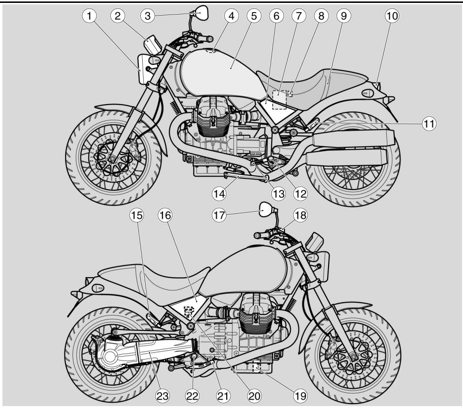
Ubicación componentes principales (02_01)
Arrangement of the main components (02_01)
02_01
Leyenda:
- Faro delantero
- Tablero de instrumentos
- Espejo retrovisor izquierdo
- Tapón del deposito de combustible
- Depóstito combustible
- Carenado lateral izquierdo
- Batería
- Portafusibles principales
- Asiento conductor/pasajero
- Faro trasero
- Estribo izquierdo pasajero
- Estribo izquierdo del conductor
- Palanca de mando del cambio
- Caballete lateral
- Estribo derecho pasajero
- Carenado lateral derecho
- Espejo retrovisor derecho
- DepoSito liquido freno delantero
- Filtrto aceite motor
- Depóstito de liquido del freno trasero
- Palanca de mando del freno trasero
- Estribo derecho conductor
- Horquilla trasera monobrazo
Key:
- Front headlamp
- Instrument panel
- Left rear-view mirror
- Fuel tank cap
- Fuel tank
- Left side fairing
- Battery
- Main fuse box
- Rider/passenger saddle
- Rear light
- Passenger left footrest
- Rider left footrest
- Gear shift lever
- Side stand
- Passenger right footrest
- Right side fairing
- Right rear-view mirror
- Front brake fluid reservoir
- Engine oil filter
- Rear brake fluid reservoir
- Rear brake control lever
- Rider right footrest
- Single arm fork
02_02
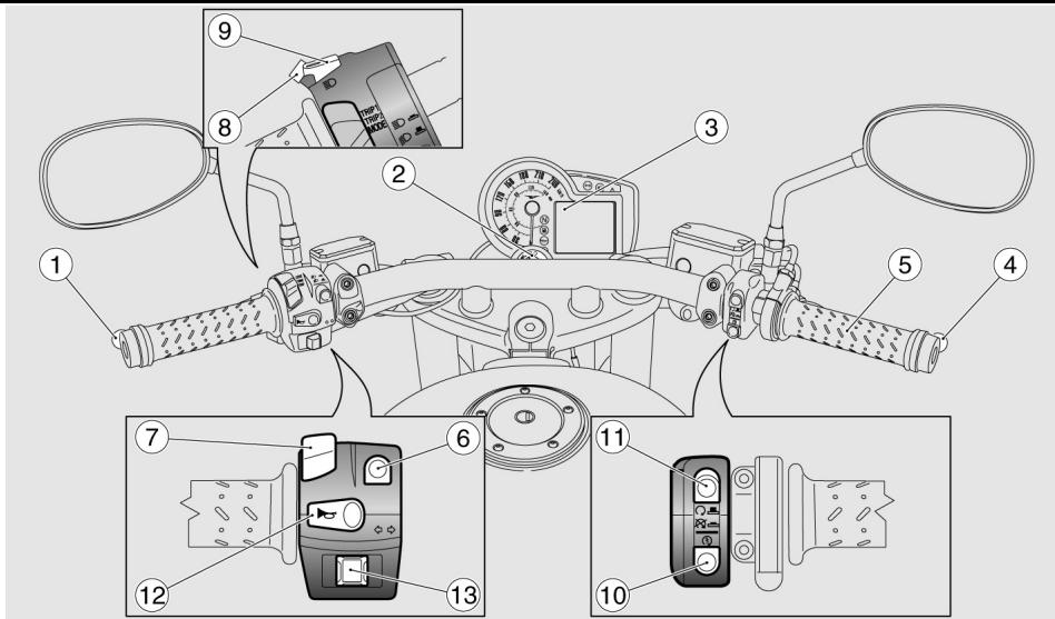
Tablero de instrumentos (02_02)
Leyenda:
- Palanca de mando embrague
- Conmutador de arranque bloqueo del manillar
- Instrumentos eindicadores
- Palanca del freno delantero
- Puno del accelerator
- Conmutador de luces
- Selector de sistemas Pantalla
- Pulsador destello luz de carretera
Dashboard (02_02)
Key:
- Clutch control lever
- Steering lock ignition switch
- Instruments and gauges
- Front brake lever
- Throttle grip
- Light switch
- Display functions selector
- High-beam flashing switch
- SET button
-
Starter button
-
Pulsador SET
- Pulsador de arranque
- Pulsador de parada del motor
- Pulsador claxon
-
Interruptor intermitentes
-
Engine stop button
- Horn button
- Turn indicator switch
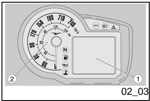
Conjunto de instrumentos (02_03)
Leyenda:
- Pantalla digital multifunción
- Velocímetro (cuentakilómetros/ cuentamillas)
Instrument panel (02_03)
Key:
- Multifunctional digital display
- Speedometer (odometer in kilometres/ miles)
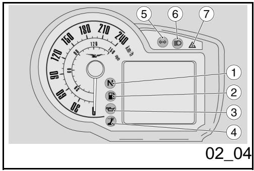
Grupo testigos (02_04)
Leyenda:
- Testigo cambio en punto muerto (color verde)
- Testigoresa del combustible (color anaranjado)
- Testigo de presión de aceite motor (color rojo)
- Testigo caballete lateral (color amarillo)
- Testigo intermitentes (color verde)
- Testigo luz de carretera (color azul)
- Testigo recapitulativo de las alar
Light unit (02_04)
Key:
- Gear in neutral warning light (green)
- Low fuel warning light (orange)
- Engine oil pressure warning light (red)
- Side stand warning light (yellow)
- Turn indicator warning light (green)
- High-beam warning light (blue)
- Alarm summary warning light / immobilizer activation - alarms (red)
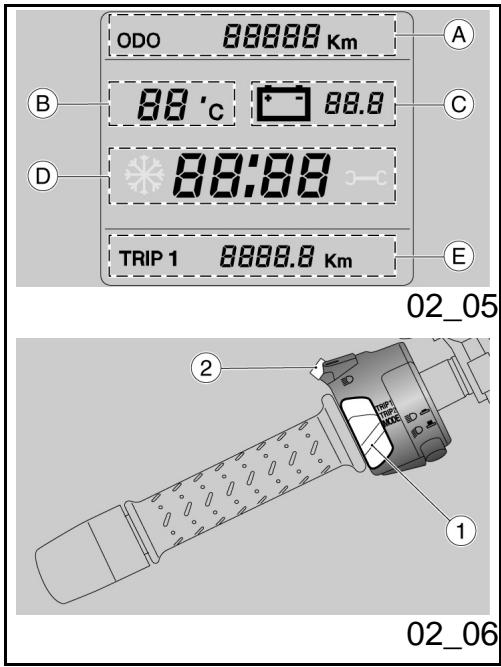
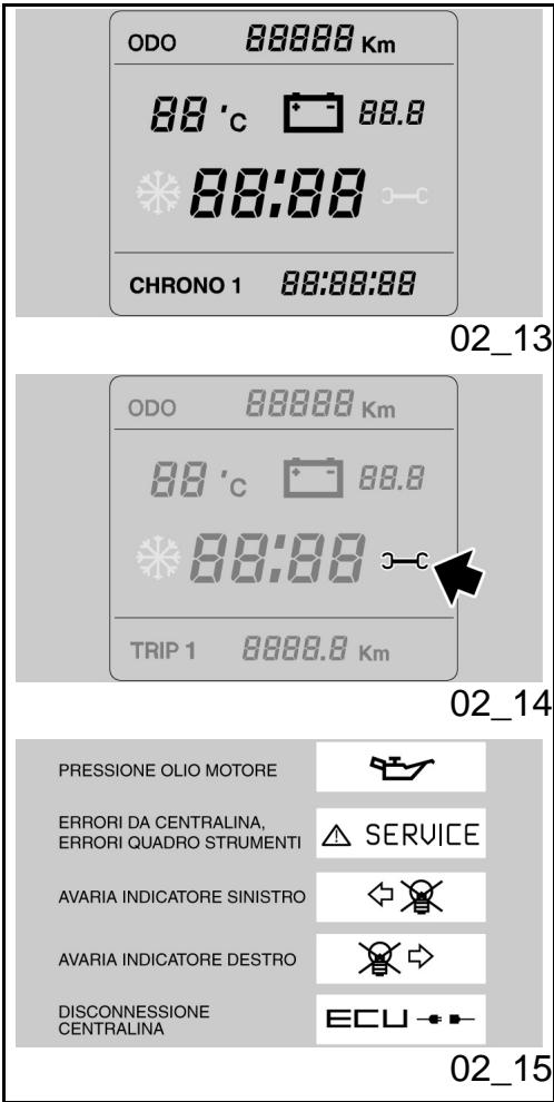
Representacion visual digital por cristales liquidos (02_05)
Girando la llave de encendido a la posicion ON, en la pantalla se encienden durante dos segundos:
- el logotipo
- todos los testigos
- la retroiluminación
Luego de dos segundos, todos los instrumentos indicaran instantanamente el valor actual de las magnitudes medidas.
Las programaciones estandar que se visualizan en la pantalla son:
- ODÔMETRO (zona A)
- TEMPERATURA AMBIENTE (zona B)
- TENSION BATERIA (zona C)
- RELOJ (zona D)
- Orderador de viaje y sistemas complementarias (zona E)
Digital Icd display (02_05)
The following indicators will light up for a couple of seconds on the instrument panel when the ignition key is set to "ON":
- the logo
- all warning lights
- the instrument panel backlighting
After two seconds, all instruments immediately show the current value of the measurements read.
The standard indications displayed are:
-ODOMETER (zone A)
- AMBIENT TEMPERATURE (zone B)
- BATTERY VOLTAGE (zone C)
- CLOCK (zone D)
- Trip computer and additional functions (zone E)
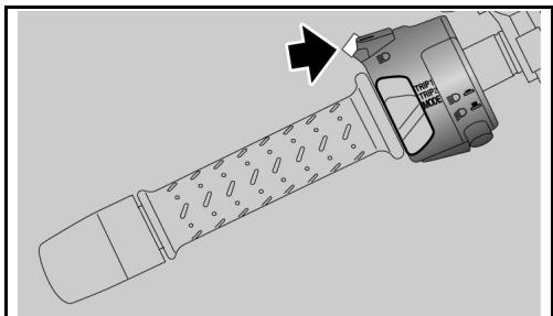
Teclas de mando (02_06, 02_07, 02_08, 02_09)
- Selector de tres posiciones: TRIP1 / TRIP2 / MODE
- Pulsador SET; con una presión breve se recorre lasDistinctasfunci-ones del MENU; con una presión larga se confirmma la seleccion.
Control buttons (02_06, 02_07, 02_08, 02_09)
- Three position selector switch: TRIP1 / TRIP2 / MODE
- SET button; pressing briefly calls up the function selection in the internal menu, holding the button down confirms the selection.
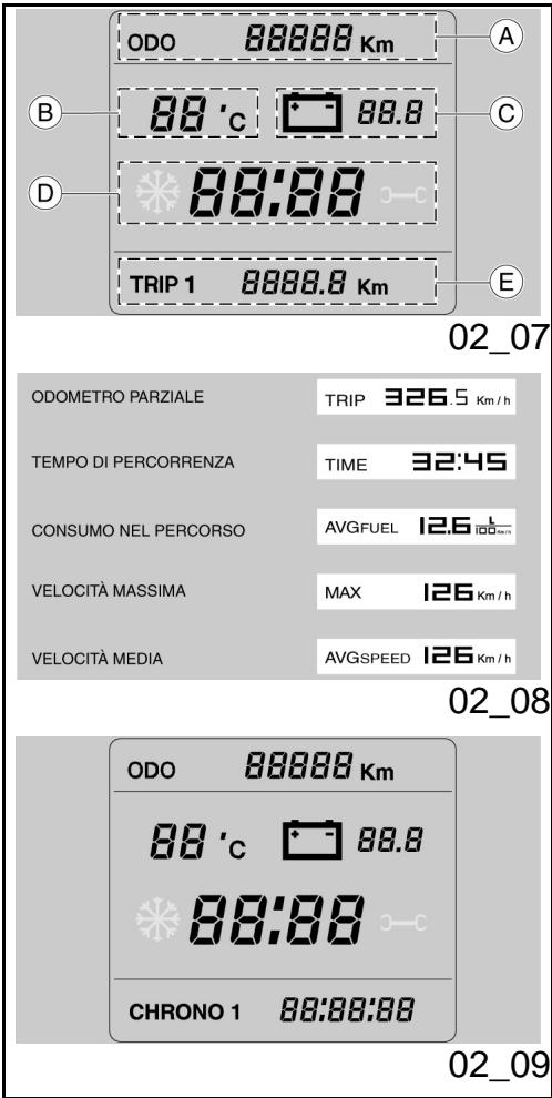
TRIP 1 y 2
En las configuraciones TRIP1 y 2 se muestran los datos correspondientes a los parciales de viaje 1 y 2.
La indicación del parcial visualizo se muestra en el ángulo inferior derecho.
Para selectionar las configuraciones TRIP 1 o TRIP 2: Colocar el selector (1) en la posi- ción correspondiente a la configuracion TRIP que quiera visualizarse.
En la zona inferior (E) de la pantalla, se visualizaras桂林antes cantidades:
- ODÔMETRO PARCIAL
- TIEMPO DE RECORRIDO
- CONSUMO DURANTE EL RECORRIDO
- VELOCIDAD MAXIMA
- VELOCIDAD MEDIA
El cambio entre una magnitud y la suscesiva
TRIP 1 AND 2
Data related to trip distances 1 and 2 are displayed at the TRIP1 and 2 configurations.
The trip odometer displayed is viewed at the bottom right angle.
To select TRIP 1 or TRIP 2 configuration: Move the selector (1) to the position corresponding to the TRIP configuration you wish to display.
The following values are viewed at the bottom zone (E) of the display:
- TRIP ODOMETER
- TRAVELLING TIME
- TRIP CONSUMPTION
- MAXIMUM SPEED
-MEAN SPEED
To shift from one value to the next, press the SET button (2) briefly. To reset all trip values
02_10


02_11
02_12
se realiza presionando brevemente el pulsador SET (2). Para poder a cero todas las magnitudes parciales del TRIP seleccionado, presionar prolongamente el pulsador SET (2).
-MODE
La configuración MODE reúne las functiones que permiten que el usuario interactue con el sistema.
Para seleccionar la configuracion MODE, colocar el selector (1) en la posicion MODE. En la zona inferior (E) de la pantalla, cada vez que se presiona el pulsador SET (2), se visualizar clicamente las siguientes cantidades:
- CONSUMO INSTANTÁNEO
- CRONÔMETRO
- MENU (función excluida con vehiculo en movimiento)
La funciona CONSUMO INSTANTÁNEO no permite interacciónes con el usuario.
CRONÉMETRO
Para utiliser el cronómetro, desde la configuración MODE, presionando brevamente il pulsador SET (2), selecciónar la funciona CRONÓMETRO. En la zona inferior de la pantalla se visualiza el mensaje CHRONO y
of the TRIP selected, push and hold the SET button (2).
MODE
The MODE configuration includes the functions that allow the user to interact with the system.
To select the MODE configuration, set the selector (1) to MODE. The following values are viewed cyclically at the bottom zone (E) of the display each time the SET button (2) is pushed:
- CURRENT CONSUMPTION;
- CHRONOMETER
-MENU (function disabled when riding)
The CURRENT CONSUMPTION function does not admit interaction with the user.
CHRONOMETER
In order to use the chronometer, from MODE setting, press the SET button (2) briefly and select the CHRONOMETER function. The bottom zone of the display shows the word CHRONO next to the number of the last
alazoledelnmero delaultima mediconrealiza y el dato medido.
Presionando brevamente el pulsador SET (2), el cronómetro comienza a registrar unaewsuen. Presionando neutramente el pulsador SET (2)antes de los diez segundos del inicio, la medicación se anula y comienza una newa medicion.
Presionando-Newamente el pulsador SET (2) diez seguidos despues del inicio, la medicación se interrupme, se memoriza y comienza una nuevo medicación.
La série de mediciones se interruppe presionando prolongamente el pulsador SET (2).
Luego de haber realizado cuarenta conteos, no se pueda realizar más medicaciones y se visualiza el mensaje "FULL". Para leer las medicaciones cronometricas adquiridas, esnecessary para la motocicletta y entrada en la funciona VISUALizar MEDIDAS del menu CRONOMETRO.
Funciones avanzadas (02_10, 02_11, 02_12, 02_13, 02_14, 02_15)
MENU
Si elvehiclesta parado y el selector está en MODE,sepuedecederalmenu de configuracionde la pantalla MENU.Pareretrarendichafuncion,confirmarla seleccion
measurement and the value registered.
After pressing the SET button (2) briefly, the chronometer starts to time again. Press the SET button (2) again within ten seconds of the start to cancel the timing operation and to begin a new measurement.
Press the SET button (2) again after ten seconds of the start to stop timing, store the time and begin a new measurement.
The series of measurements is interrupted by pressing and holding down the SET button (2).
The word "FULL" is displayed after forty times are stored. No more times can be stored. In order to read the chronometer times it is necessary to stop the vehicle and display the VIEW MEASUREMENTS function of the CHRONOMETER menu.
Advanced functions (02_10, 02_11, 02_12, 02_13, 02_14, 02_15)
MENU
If the vehicle is stopped and the selector set to MODE, it is possible to access the configuration menu on the MENU screen. To display this function, confirm the selection (SET
(presionando prolongamente el pulsador SET) en MENU.
Las.optionedesmenudec configuracionson lassiguientes:
-SALIR
- PROGRAMACIONES
- CRONÔMETRO
- DIAGNOSTICO
- IDIOMAS
button held down) on the MENU.
The configuration menu options are:
-EXIT
- SETTINGS
- CHRONOMETER
- DIAGNOSIS
- LANGUAGES
PROGRAMACIONES
Cuando se confirma la selección (presionando prolongamente el pulsador SET) en PROGRAMACIONES, aparece una pantalla con las siguientesvinciones:
-SALIR
- AJUSTE HORA
- RETROILUMINACION
-°C/°F
- 12H/24H
LED INMOVILIZADOR
SETTINGS
When the selection is confirmed on SET-TINGS (SET button held down), a screen displays the following options:
-EXIT
- TIME ADJUSTMENT
- BACKLIGHTING
-°C/°F
- 12H / 24H
- IMMOBILIZER LED
- AJUSTE HORA
En esta modalidad se programa el valor del reloj. Dento de la función, cada vez que se
TIME ADJUSTMENT
The clock can be programmed with this option. Once within this option and each time
presiona el pulsador SET aumento de a uno el valor de la hora; al alcancar el valor 12 o 24, si se presiona-Newamente el pulsador SET se vuye a 1.
El paso de AM a PM o viceversa se produce con el paso de las 11:59 a las 12:00. Presionando prolongamente el pulsador SET se memoriza el valor yuda a la modalidad de regulacion de los instantos.
Cada vez que se presiona el pulsador SET se&aumenta de a uno el valor de losminutes, al alcancar el valor 59, si se presiona-Newamente el pulsador SET se vuye a 0.
El procedimiento termina presionando prolongamente el pulsador SET, el tablero(vuelve al menu PROGRAMACIONES.
the SET button is pressed, the hour value increases by one; when the value reaches 12 or 24, it goes back to 1 the next time the SET button is pressed.
The shift from AM to PM or vice versa occurs when going from 11:59 to 12:00. Hold down the SET button to store the value and shift to minute adjustment.
Each time the SET button is pressed, the minute value increases by one; when the value reaches 59, it goes back to 0 the next time the SET button is pressed.
The procedure ends when the SET button is held down, the instrument panel goes back to the SETTINGS menu.
RETROILUMINACION
Esta funciona permite regular la intensidad de la retroiluminacion en tres niveles.
Dentro de la función, presionando breve-mente el pulsador SET, aparecen@ciclicamente los siguientes iconos:
- LOW
-MEAN - HIGH
Al finalizar la operation, presionando prolongamente el pulsador SET, la pantalla vuelve al menu PROGRAMACIONES.
BACKLIGHTING
This function adjusts backlighting to three brightness levels.
Once within this function, each time the SET button is pressed, the following icons are cyclically displayed:
- LOW
-MEAN
-HIGH
The procedure ends when the SET button is held down, the instrument panel goes back to the SETTINGS menu.
^ C / ^
Estamericana la unidad de medida de las temperatas ambiente. Dento de la funcion, presionando brevamente el pulsador SET, aparecen ciclicamente las dos unidades de medida:
-°C
-°F
Presionando prolongamente el pulsador SET, se memoriza el dato y el tablero vuel al menu PROGRAMACIONES.
12H/24H
Estamericana la modalidad de visualizacion de la hora. Dento de la referencia, presionando brevamente el pulsador SET, aparecen clicamente los dos formatos:
-12H
-24H
Presionando prolongamente el pulsador SET, se memoriza el dato y el tablero vuel al menu PROGRAMACIONES.
LED INMOVILIZADOR
Esta funciona permite habilar / deshabilitar eldestillo del led alarma bajo del cuadrante
^ C / ^
This function selects the ambient temperature unit of measurement. Once within this function, each time the SET button is pressed, the two units of measurement are cyclically displayed:
-°C
-°F
Hold down the SET button to store the data; the instrument panel goes back to the SETTINGS menu.
12H/24H
This function selects the time display mode. Once within this function, each time the SET button is pressed, the two formats are cyclically displayed:
-12H
-24H
Hold down the SET button to store the data; the instrument panel goes back to the SETTINGS menu.
IMMOBILIZER LED
This function enables/disables the alarm LED flashing in the fuel level dial. It is used
del nivel del combustible. Se usa en caso en que se conecte un antirrboro exterior.
when an external antitheft device is connected.
CRONÉMETRO
Cuando se confirma la seleccion (presionando prolongamente el pulsador SET) en CRONOMETRO, aparece una pantalla con las siguientesustralianos:
-SALIR
- VISUALIZAR MEDIDAS
- BORRAR MEDICIONES
CHRONOMETER
When the selection is confirmed on CHRONOMETER (SET button held down), a screen displays the following options:
-EXIT
- VIEW TIMES
- DELETE TIMES
Visualizar mediciones
Estamericano.
Presionando brevemente el pulsador SET se deslizan las páginas de mediciones, presionando prolongadamente, la pantalla vuel al menu CRONÓMETRO.
Si la bateria se desconecta, se pierden los tiempos memorizados.
View times
This function displays the stored chronometer times.
Press the SET button for a couple of seconds to scroll the measurements screens; hold it down to display the CHRONOMETER menu.
If the battery is removed, the stored times are lost.
Borrar mediciones
Este item borra las mediciones cronometricas realizadas. Se solicita la confirmacion del bomrado.
Delete times
This option deletes the stored chronometer times. A deletion confirmation is requested.
Once the operation is finished, the display
Al finalizar la operationla pantalla vuela al menu CRONOMETRO.
shows the CHRONOMETER menu.
DIAGNOSTICO
Esta funciona se interconecta con los sistemas presentes en la moto y sobre ellos ejecta el diagnóstico. Para habilitarla se debe introducir un número de acceso que solo poseen los centros de assistencia Moto Guzzi.
DIAGNOSIS
This function interfaces with the systems present on the motorcycle and diagnose them. To enable this function, enter an access code available only from Moto Guzzi service centres.
IDIOMAS
dentro de esta funciona se pueda selectionar el idioma de la pantalla. Las-optiones que seSEOuen selectionar son:
-ITALIANO
- ENGLISH
- FRANÇAIS
- DEUTSCHE
- ESPANOL
Al finalizar la operation, la pantalla vuelve al menu IDIOMA.
LANGUAGES
The display language can be selected with this function. The available options are:
-ITALIANO
- ENGLISH
- FRANCAIS
- DEUTSCH
- ESPAGNOL
Once the operation is finished, the display shows the LANGUAGEs menu.
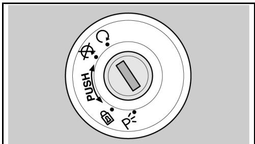
UMBRAL SERVICE
Al superar los umbrales de los intervalos de mantenimiento, aparece un icono con el simbolo de la llave inglesia.
SERVICE THRESHOLD
When the threshold of the maintenance intervals is exceeded, an icon with a spanner is shown.
Primer encendido: 1.000km (625 mi)
Encendidos sucesivos: cada 10.000 km (6.250 mi)
First ignition: 1,000 km (625 mi)
Subsequent ignitions: every 10,000 km (6,250 mi)
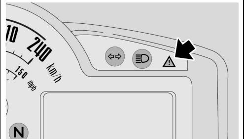
VISUALIZACION ALARMAS
En el caso de que se detecte una anomalía grave, que pueda compenser la integridad del vehiculo o de la persona, en la zona inferior de la pantalla se visualiza un icono queSEA la causa de la anomalía.
Las alarmas se dividen en dos grupos, según su prioridad:
- Prioridad alta: Presión aceite motor, Errores de centralita y Errores tablero.
- PRIORITY Baja: Intermitentes y Desconexión centralita.
En el caso se presenten contemporáneamente mas de una alarma de igual prioridad, los iconos correspondientes se visualizaran en forma alternada.
Las alarmas de alta prioridad他们在 visualización de las de baja prioridad
Si se encienden durante lapsos breves el testigo de alarmay y el icono de SERVICE, no son indices de un mal funciona.
VIEWALARMS
In case of a serious failure which jeopardises the integrity of the vehicle or rider, an icon indicating the cause is displayed on the bottom area.
The alarms are subdivided into two groups according to their priority:
- High priority: Engine oil pressure, Control unit errors and Instrument panel errors.
- Low priority: Turn indicators and Control unit disconnected.
If there are more than one alarm of equal priority simultaneously, the corresponding icons are displayed alternately.
High priority alarms inhibit the displaying of low priority alarms.
Brief warning light and SERVICE icon lighting do not signal malfunctioning.
02_16
02_17
02_18
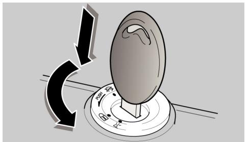
Conmutador de encendido (02_16)
El interruptor de arranque se enquiryra en la placaca superior del manguito de direccion.
Con el vehiculo seentaegan dos llaves (una de reserva).
Las luces se apagan cuando el interruptor de arranque está en «OFF»
NOTA
LA LLAVE ACCIONA EL CONMUTADOR DE ARRANQUE/BLOQUEO DEL MANI-LLAR, LA CERRADURA DEL TAPON DEL DEPOSITO DEL COMBUSTIBLE Y LA CERRADURA DEL ASIENTO
NOTA
LAS LUCES SE ENCIENDEN AUTOMÁTICAMENTE AL ARRANCAR EL MOTOR.
LOCK: La direccion está bloqueada. No es possible poder en marcha el motor y acontecer las luces. Se pueda sacar la llave
OFF: El motor y las luces no se puedaponer en funciona. Se pueda SACAR la llave.
ON: El motor se puedaponer en configuracion.iento.No se peut SACAR la llave
Ignition switch (02_16)
The ignition switch is located on the headstock upper plate.
The vehicle is supplied with two keys (one is the spare key).
The light switch turns off when the ignition switch is set to «KEY OFF».
NOTE
THE KEY ACTIVATES THE IGNITION SWITCH/ STEERING LOCK, THE FUEL TANK CAP LOCK AND THE SADDLE LOCK.
NOTE
THE LIGHTS TURN ON AUTOMATICALLY UPON THE ENGINE START-UP.
LOCK: The steering is locked. It is not possible to start the engine or switch on the lights. The key can be extracted
OFF: The engine and lights cannot be set to work. The key can be extracted.
ON: The engine can be started. The key cannot be extracted.
Bloqueo del volante (02_17)
Para bloquear la direccion:
- Girar el manillar Completely hacer la izquierda.
- Girar la llave a la posicion «OFF».
- Presionar y girar la llave en sentido antihorario (hacia la izquierda), virar lentamente el manillar hasta colocar la llave en «LOCK».
- Sacar la llave.
Locking the steering wheel (02_17)
To lock the steering:
- Turn the handlebar completely to the left.
- Turn the key to «OFF».
- Push in the key and turn it anticlockwise (to the left), steer the handlebar slowly until the key is set to «LOCK».
- Remove the key.
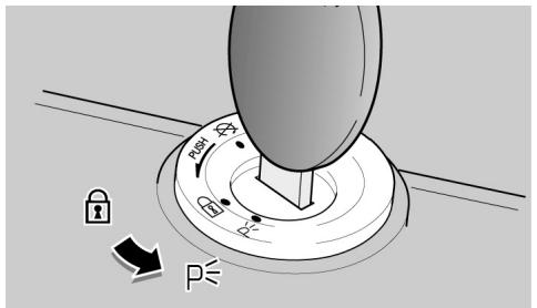
Luces de aparecimiento (02_18)
El vehiculo está equipado con luces de aparcimiento delanteras y traseras. Avec es preferible aparcar el vehiculo en las areas especialicas y en Lugares iluminados, las luces de aparcimiento son muy utiles en caso que seanecessary aparcar en un area oscura o poco iluminada, o cuando se desea hacer más visible el vehiculo.
FUNCTIONAMIENTO
Para encender las luces de aparcamento:
- Bloquear la direccion sin extraer la llave.
Girar la llave a la posicion (PARKING). - Controller que ambas luces de apar-cimiento (delantera y trasera) se
Parking lights (02_18)
The vehicle has front and rear parking lights. Considering that it is preferable to park the vehicle in adequate and well-lit areas, parking lights are very useful when parking the vehicle in a dark or poorly lit area and when the vehicle needs to be visible.
OPERATION
To turn on the parking lights:
- Block the steering but do not take out the key.
- Turn the key to PARKING.
- Check that both parking lights (front and rear) turn on properly.
Take out the key.
hayan encendido correctamente.
- Quitar la llave.
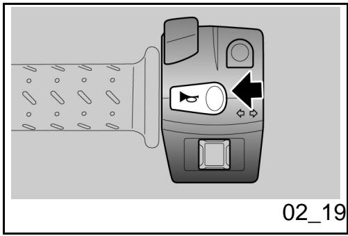
Pulsante claxon (02_19)
Presionado, pone en funciona el avisador sonoro.
Horn button (02_19)
Press it to activate the horn.
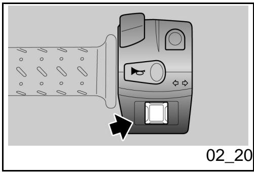
Conmutador intermitentes (02_20)
Para girar hacla izquierda,desplazar el intern-. turtor hacla izquierda;para girar hacla derecha,desplazar el interruptor hacla derecha.Presionar el interruptor para desactivar el intermitente.
ATENCLON
SI EL TESTIGO FLECHAS PARPADEA RÁPIDAMENTE, SIGNIFICIA QUE UNA O AMBAS BOMBILLAS DE LOS INTERMISTENTES ESTÁN QUEMADAS.
Switch direction indicators (02_20)
Move the switch to the left, to indicate a left turn; move the switch to the right, to indicate a right turn. Pressing the switch deactivates the turn indicator.
CAUTION
IF THE WARNING LIGHT WITH ARROWS FLashes QUICKLY, IT MEANS THAT ONE OR BOTH TURN INDICATORS LIGHT BULBS ARE BURNT OUT.
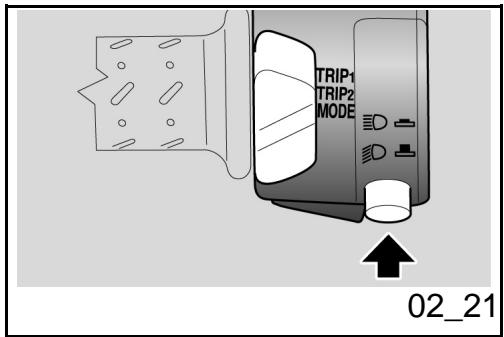
Commutador luces (02_21)
Presionando el conmutador de luces se enciende la luz de carretera; al presionarlo-Newamente se enciende la luz de cruce.
High/low beam selector (02_21)
Press the light switch to turn on the high-beam light; press it again to turn on the low-beam light.
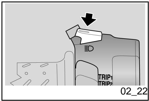
Pulsador rafaga luz de carretera (02_22)
Permite utiliser el destello de la luz de carretera en casos de peligro o emergencia.
Al liberar el pulsador se desactiva el destello de la luz de carretera.
Passing button (02_22)
Uses the high-beam flash in case of danger or emergency.
Releasing the switch deactivates the high-beam flash.
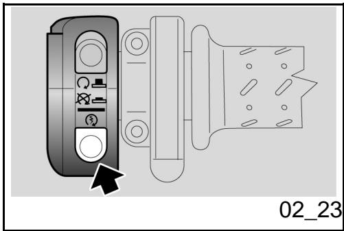
Pulsante arranque (02_23)
Presionando el pulsador, el arrancador pone en funciona el motor.
Start-up button (02_23)
Press the button and the starter motor spins the engine.
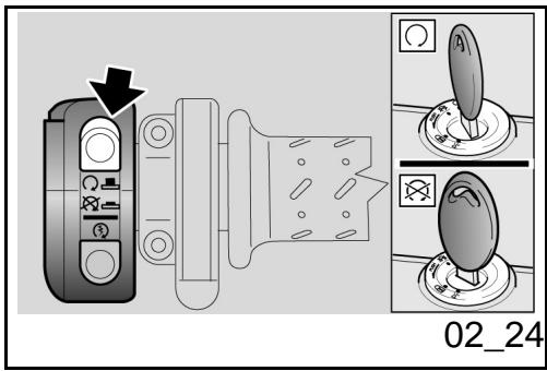
Interruptor parada motor (02_24)
Cuple la función de interruptor de seguidad o de emergencia.
Presionar el interruptor para parar el motor.
Engine stop switch (02_24)
It acts as an engine cut-off or emergency stop switch.
Press this switch to stop the engine.
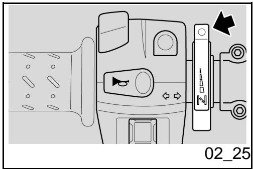
Mando del starter manual (02_25)
Al girar hacía abajo la palanca para el arranque en frío,enta en funciona el starter para elmentionado arranque del motor.
Para desactivar elstarter,learvar la palianca paraelarranque en frío a la posición inicial.
Manual starter control (02_25)
By turning the cold start lever downwards, the engine cold start starter begins working.
To disconnect the starter, restore the cold start lever to its initial position.
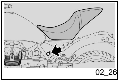
Abertura sillín (02_26)
- Colocar el vehiculo sobre el caballete.
- Introducir la llave en la cerradura del asiento.
Girar la llave en sentido horario, levantar y sacar el asiento por la parte posterior
Para bloquear el asiento:
- Positionar la parte delantera del asiento en su alojamento y bajo la parte trasera.
- Presionar sobre la parte trasera, hasta que calce la cerradura.
ATENCIón
ANTES DE BAJAR Y BROQUEAR EL ASIENTO, CONTROLAR DE NO HABER OLVIDADO LA LLAVE EN LOS COMPARTIMIENTOS PORTADOCUMENTOS/KIT
Opening the saddle (02_26)
Rest the vehicle on its stand.
- Insert the key in the saddle lock.
- Turn the key clockwise, lift and remove the saddle afterwards
To lock the saddle:
- Place the saddle front part in its seat and lower the rear part.
- Press the rear part to trip the lock.
CAUTION
BEFORE LOWERING AND LOCKING THE SADDLE, CHECK THAT THE KEY HAS NOT BEEN LEFT IN THE GLOVEBOX / TOOL KIT COMPARTMENT.

BEFORE RIDING, MAKE SURE THAT THE SADDLE IS CORRECTLY LOCKED.
HERRAMIENTAS.

ANTES DE CONDICIR ASEGURARSE DE QUE EL ASIENTO ESTÉ CORRECTAMENTE BLOQUEADO.
Compartmento porta-doc./kit herramentas
Para acceder al compartmento portadocumentos / kit de Herramentas, sacar el asiento.
Glove/tool kit compartment
Remove the saddle to have access to the glove-box / toolkit compartment.
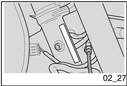
La identificacion (02_27, 02_28)
Es convenienteayar notable de los nombres del chasis y del motor, en el espacio reservado para los mismos en el presente manual. El número de chasis pueda serutil para adquirir piezas de repuesto.
ATENCLON

LA ALTERACION DE LOS NUMEROS DE IDENTIFICACION PUEDE ACARREAR GRAVES SANCIONES PENALES Y ADMINISTRativas. EN PARTICULAR, LA AL
Identification (02_27, 02_28)
Write down the chassis and engine number in the specific space of this booklet. The chassis number is handy when purchasing spare parts.
CAUTION

ALtering IDENTIFICATION NUMBERS IS AN OFFENCE WHICH CAN RESULT IN SEVERE CRIMINAL AND ADMINISTRATIVE CHARGES. PARTICULARLY MODIFYING THE CHASSIS NUMBER WILL IMMEDIATELY INVALIDATE THE WARRANTY.
TERACION DEL NUMERO DE CHASIS IMPLICA LA INMEDIATA CADUCIDAD DE LA GARANTIA
NUMERO DE CHASIS
El número de chasis está estampillado en el manguito de direccion,lucko.
Chasis n°
CHASSIS NUMBER
The chassis number is stamped on the right side of the headstock.
Chassis No.
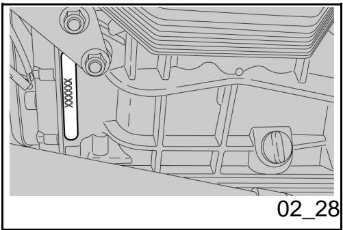
NUMERO DE MOTOR
El número de motor está estampillado en la bancada del carter motor bajo izquierdo.
Motor n°
ENGINE NUMBER
The engine number is printed on the base of the left side engine crankcase.
Engine No.
Bellagio


Cap. 03
El uso
Chap. 03
Use
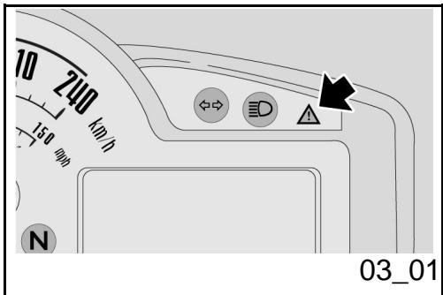
Controles (03_01)
ATENCLON
ANTES DE LA PARTIDA, REALIZAR SIempre UN CONTROL PRELIMINAR DEL VEHICULO PARA OBTENER UN CORRECTA Y SEGURA FUNCIONALIDAD. EL HECHO DE NO REALIZAR DICHAS OPERaciones PUEDE CAUSAR GRAVES LESIONES PERSONALES O DANOS GRAVES AL VEHICULO. SI NO SE COMPRENE DEL FUNCIONAMIENTO DE ALGUN MANDO O EN EL CASO DE QUE SE DETECTE O SE SOSPECHE DE ALGUNA ANOMALIA DE FUNCIONAMIENTO, DIRIGIRSE A UN Concesionario Oficial Moto Guzzi. EL TIEMPO NECESARIO PARA UN CONTROL ES MUY BREVE Y RESULTA MUY VENTAJOSO PARA LA SEGURIDAD.
Checks (03_01)
CAUTION
BEFORE SETTING-OFF, ALWAYS CARRY OUT A PRELIMINARY CHECK OF THE VEHICLE, FOR CORRECT AND SAFE OPERATION. FAILURE TO DO SO MAY LEAD TO SEVERE INJURY OR VEHICLE DAMAGE. DO NOT HESITATE TO CONTACT AN Official Moto Guzzi Dealer IF YOU DO NOT UNDERSTAND HOW SOME CONTROLS WORK OR IF MALFUNCTIONING IS DETECTED OR SUSPECTED. CHECKS DO NOT TAKE LONG AND RESULT IN SIGNIFICANTLY ENHANCED SAFETY.
Estevehicleostapepreparadoparaidentificar, en tiemporeal, eventuales anomalías defuncioncimiento,memorizadas porla centralitaelectrónica.
Cada vez que el conmutador de arranque se positionala en "ON", en el tablero se enciende, durante aproximamente tres segundos, el testigo LED alarma.
This vehicle has been programmed to indicate in real time any operation failure stored in the electronic control unit memory.
Every time the ignition switch is turned to "KEY ON", the alarm LED warning light turns on for about three seconds on the instrument panel.
CONTROLES PRELIMINARES
| Characterística | Descripción/Valor |
| Freno de disco delantero ytrasero | Controlar el funcionaimiento, la carrera en vacío de las palancas de mando, el nivel del liquido y eventuales perdidas. Controlar el desgaste de las pastillas. Si es必須o efectuar el lienado del liquido de frenos. |
| Accelerador | Controlar que funciona con suavidad y que se pueda abrir y cerrar Completely, en todas las posiciones de la direction. Regular y/o lubricar si es必須ario. |
| Aceite motor | Controlar y/orestaurant el nivel si es必須ario. |
| Ruedas/neumáticos | Controlar el estado superficial de los neumáticos, la presión de inflado, el desgaste y eventuales daños.Quitar eventualesyerpos extraños encastrados en las esculturas de la banda de rodadura. |
| Palancas del freeno | Controlar que funciona con suavidad. |
PRE-RIDE CHECKS
| Specification | Desc./Quantity |
| Front and rear disc brake | Check for proper operation. Check brake lever empty travel and brake fluid level. Check for leaks. Check brake pads for wear. If necessary top-up with brake fluid. |
| Throttle grip | Check it functions smoothly and that it can be fully opened and closed at all steering positions. Adjust and/or lubricate if necessary. |
| Engine oil | Check and/or top up as required. |
| Wheels/tyres | Check that tyres are in good conditions. Check inflation pressure, tyre wear and potential damage. Remove any possible strange body that might be stuck in the tread design. |
| Brake levers | Check they function smoothly. Lubricate the joints and adjust the travel if necessary. |
| Clutch | Check for proper operation. Check clutch lever free play and |
| Lubricar las articulaciones y regular la carrera si es Neededo. | |
| Embrague | Controlar el funciona, la carrera en vacío de la palanca de mando, el nivel del liquido y eventuales perdidas. Si esneededario, efectuar el llenado del liquido: el embragueDebe funciona sin tironeos ni deslizamente. |
| Dirección | Controlar que la rotación sea homogénea, fácilmente desizable y sin juego ni aflojamente. |
| Caballete central - lateral | Controlar que funciona. Controlar que durante el descenso y el ascenso del caballete no haya frictiones y que la tensión de los muelles lo regrese a su posición normal. Lubricar los acoplamente y las articulaciones si es需要用. Controlar el correcto funciona del interruptor de seguridad. |
| Elementos de fijación | Controlar que los elementos de fijación no se estén flojos. Eventualmente, regular o averter. |
| Depósito combustible | Controlar el nivel y reabastecer si es需要用. |
| fluid level. Check for leaks. If needed, top-up the fluid; the clutch must work without gripping and/or sliding. | |
| Steering | Check that the rotation is homogeneous, smooth and there are no signs of clearance or slackness. |
| Centre - side stand | Check it works properly. Check that there is no friction when the side stand is pulled up and down and that the spring tension makes it snap back to its rest position. Lubricate couplings and joints if necessary. Check the safety switch for correct operation. |
| Clamping | Check that the clamping elements are not loose. Adjust or tighten them as required. |
| Fuel tank | Check the coolant level and refill if necessary. Check the circuit for potential leaks or obstructions. Check that the tank cover closes correctly. |
| Engine stop switch (ON - OFF) | Check for its correct operation. |
| Controlar las eventuales perdidas u occlusiones del circuito. Controlar que el tapón del combustible está correctamente cerrado. | |
| Interruptor de parada del motor (ON - OFF) | Controlar el funcionacorrecto. |
| Luces, testigos, avisador sonoro, interruptores luz de stop trasera y dispositivos electricos | Controlar el funcionacorrecto de los dispositivos sonoros y visuales. Sustuir las bombillas o intervir en caso de avería. |
| Aceite de transmisión - Guzzi | Controlar. Si fue此人ccasio llenar, dirigirse a un taller autorizzato Moto Guzzi. |
| Lights, warning lights, horn, rear stop light switch and electrical devices | Check the correct operation of the horn and lights. Replace the bulbs or repair any malfunctions. |
| Transmission oil - Guzzi | Check. If topping up is necessary, contact an authorised Moto Guzzi workshop. |
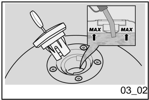
Abastecimiento (03_02)
Para reabastecer el combustible:
- Introducir la llave en la cerradura tapón del deposito
Girar la llave en sentido horario, tirar yAbrir la tapa del combustible.
Reabastecer.
ATENCIón

Refuelling (03_02)
To refuel:
- Insert the key in the fuel tank lock.
- Turn the key clockwise, pull and open the fuel cap.
Refuel.
CAUTION

DO NOT ADD ADDITIVES OR ANY OTHER
NO AGREGAR ADITIVOS U OTRAS SUSTANCIAS AL COMBUSTIBLE.
SI SE USA UN EMBUDO U OTRO OBJECTO, ASEGURARSE DE QUE ESTÉ PERFECTAMENTE LIMPIO.

NO LLENAR COMPLETAMENTE EL DEPOsITO;EL NIVEL MAXIMO DE COMBUSTIBLE DEBE PERMANECER POR DEBAJO DEL BORDE INFERIOR DEL COLECTOR (VER FIGURA).
Characteristicas Tecnicas
Combustible (incluido reserva)
19 +/- 0.5 I (5.02 +/- 0.13 US gal)
Reserva de combustible
4 I (1.06 US gal)
SUBSTANCES TO THE FUEL.
WHEN USING A FUNNEL OR ANY OTHER ELEMENT, MAKE SURE IT IS PERFECTLY CLEAN.

DO NOT FILL THE TANK UP TO THE RIM; FUEL MAXIMUM LEVEL MUST ALWAYS BE BELOW THE LOWER EDGE OF THE FILLER NECK (SEE FIGURE).
Characteristic
Fuel (reserve included)
19 +/- 0.5 I (5.02 +/- 0.13 US gal)
Fuel reserve
4 I (1.06 US gal)
efectuado el reabastecimiento:
- El tapón puede cerrarse solamente con la llave introducida.
- Con la llave introducida, volver a cerrar eltapón, presionándolo.
Sacar la Ilave.
after refuelling:
- The cap can only be closed if the key is inserted.
- Once the key is inserted, press the cap to close it again.
- Extract the key.

ASEGURARSE DE QUE LA TAPA ESTÉ CORRECTAMENTE CERRADA.

MAKE SURE THE CAP IS TIGHTLY CLOSED.
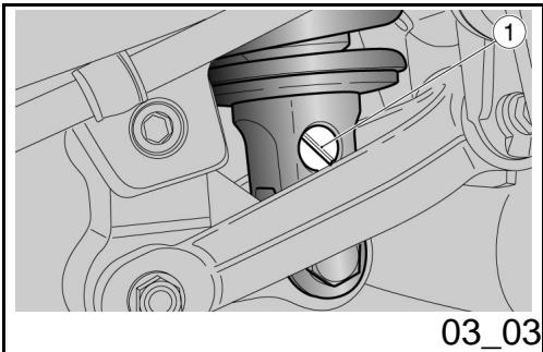
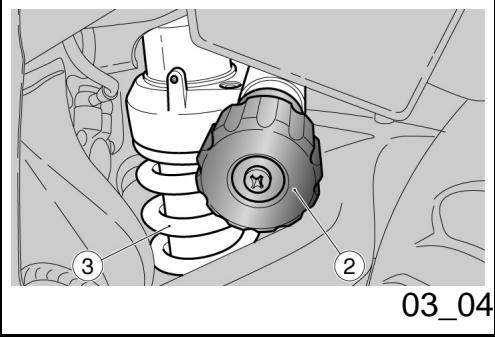
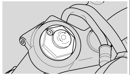
Regulación amortiguedorestraseros (03_03, 03_04)
La suspENSION trasera esta compuesta por el grupo muelle-amortiguador, que se conecta mediante silent-block, al chasis y por medio de articulaciones de levas, a la horquilla trasera.
Para regular el ajuste del vehiculo, el amortiguidor consta de:
- un tornillo de regulación (1) para regular el frenado hidráulico en extension;
- un pomo de regulación (2) para regular la precarga del muelle (3).
REGULACION DEL AMORTIGUADOR TRASERO
La programación estándar del amortiguidor trasero ha sido previsto para satisfacer la mayoría de las conditiones de conducccion a velocidad moderada o elevada, para el transporte del conductor con equipaje.
Sin embargo es possible personalizar la regulacion en referencia del uso del vehiculo.

ANTES DE OPERAR EN LOS DISPOSITI
Rear shock absorbers adjustment (03_03, 03_04)
The rear suspension consists of a springshock absorber unit linked to the frame via silent-block and to the rear fork via a linkage system.
To set the vehicle suspension, the shock absorber has:
- a set screw (1) to adjust the hydraulic rebound damping;
- a set knob (2) for spring (3) preloading adjustment.
REAR SHOCK ABSORBER ADJUSTMENT
Standard rear shock absorber setting is adjusted to suit most high and low speed riding conditions, to transport the rider plus luggage.
However, this set can be modified for specific needs according to vehicle use.

ALLOW ENGINE AND EXHAUST SILENCER TO COOL OFF BEFORE OPERATING THE SET SCREWS.
REGULACION DEL AMORTIGUADOR TRASERO
| Característica | Descripción/Valor |
| Regulación en compresión, pomo (2) (solamente conductor) | de totalmente abierto, cerrar (sentido horario) 6 clicks |
| Regulación en extensión, tornillo (1) (solamente conductor) | de totalmente cerrado,Abrir (sentido antihorario) 12 clicks |
| Regulación en compresión, pomo (2) (conductor + pasajero) | de totalmente abierto, cerrar (sentido horario) 30 clicks |
| Regulación en extensión, tornillo (1) (conductor + pasajero) | de totalmente cerrado,Abrir (sentido antihorario) 9 clicks |
REAR SHOCK ABSORBER ADJUSTMENT
| Specification | Desc./Quantity |
| Compression adjustment, knob (2) (only rider) | close (clockwise) 6 clicks from fully open |
| Rebound adjustment, screw (1) (only rider) | open (anticlockwise) 12 clicks from fully closed |
| Compression adjustment, knob (2) (rider + passenger) | close (clockwise) 30 clicks from fully open |
| Rebound adjustment, screw (1) (rider + passenger) | open (anticlockwise) 9 clicks from fully closed |
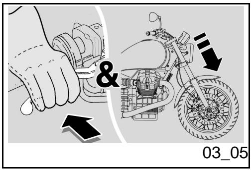
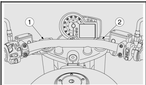
Regulación horquilla delantera (03_05, 03_06, 03_07)
Con la palanca del freno delantero actionada, presionar repetidamente en el manillar, empujando a fondo la horquilla. La carrera debe ser suave y los vastosos no deben evideciar marcas de aceite.
Controlar el ajuste de todos los organismos y el
Front fork adjustment (03_05, 03_06, 03_07)
Operating the front brake lever, press the handlebar repeatedly to send the fork fully down. The stroke should be soft and there should be no oil marks on the stems.
Check the tightening of all the elements and the correct operation of the front and rear suspension joints.
03_06
03_07
funcionamiento de las articulaciones de la suspensión delantera y trasera.
El frenado hidráulico puede regularsestownando los pomos de regulación (1) y (2).
- El pomo de regulación izquierdo (1) controla la regulación del frenado hidráulico en extension;
el pomo de regulación derecho (2) la del frenado en compresión.
Hydraulic braking can be adjusted by actuating on the set knobs (1) and (2).
- The left set knob (1) is used to adjust rebound damping;
- the right set knob (2) is used to adjust compression damping.
REGULACION DE LA HORQUILLA DELANTERA
| Characterística | Descripción/Valor |
| Regulación hidráulica en compresión, regulación (2) (solamente conductor) | De totalmente cerrado,Abrir (sentido antihorario) 12 clics |
| Regulación hidráulica en extension, regulación (1) (solamente conductor) | De totalmente cerrado,Abrir (sentido antihorario) 12 clics |
FRONT FORK ADJUSTMENT
| Specification | Desc./Quantity |
| Compression damping adjustment, set screw (2) (only rider) | Open (anticlockwise) 12 clicks from fully closed |
| Rebound damping adjustment, set screw (1) (only rider) | Open (anticlockwise) 12 clicks from fully closed |
| Regulación hidráulica en compresión, regulación (2) (conductor + pasajero) | De totalmente cerrado,ISR (sentido antihorario) 10 clics |
| Regulación hidráulica en extension, regulación (1) (conductor + pasajero) | De totalmente cerrado,ISR (sentido antihorario) 10 clics |
| Compression damping adjustment, set screw (2) (rider + passenger) | Open (anticlockwise) 10 clicks from fully closed |
| Rebound damping adjustment, set screw (1) (rider + passenger) | Open (anticlockwise) 10 clicks from fully closed |
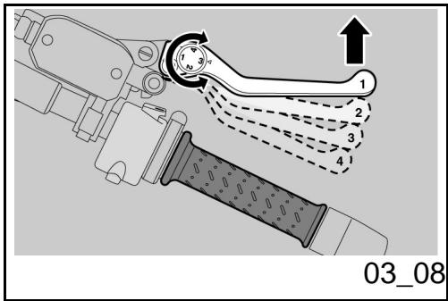
Regulación leva frenodelantero (03_08)
Se puede regular la distancia entre los extremos de la palanca y el puno, girando el dispositivo.
Las posiciones "1" y "4" corresponden a una distancia aproximada, entre el extremo de la palanca y el puno, de 105 y 85 mm (4.1 y 3.3 in) respectfully.
Las posiciones "2" y "3" corresponden a distancias intermedias.
Para la regulación: empujar la palanca deMANDo hacía adelante y girar el dispositivo hasta que el valor deseado se corresponda con la flecha de comprobación.
Justering af greb til forbremse (03_08)
Adjust the distance between the lever end and the hand grip by turning the set screw.
Positions "1" and "4" correspond to a lever end-hand grip distance of about 105 and 85 mm (4.1 - 3.3 in) respectively.
Positions "2" and "3" correspond to intermediate distances.
To adjust: push the control lever forward and turn the set screw until the arrow points at the desired number.
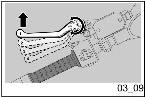
Regulación leva embrague (03_09)
Se puede regular la distancia entre los extremos de la palanca y el puño, girando el dispos-itivo.
Las posiciones "1" y "4" corresponden a una distancia aproximada, entre el extremo de la palianca y el puño, de 105 y 85 mm (4.1 y 3.3 in) respectivamente.
Las posiciones "2" y "3" corresponden a distancias intermedias.
Para la regulación: empujar la palanca deMANDo hacía adelante y girar el dispositivo hasta que el valor deseado se corresponda con la flecha de comprobación.
Clutch lever adjustment (03_09)
Adjust the distance between the lever end and the hand grip by turning the set screw.
Positions "1" and "4" correspond to a lever end-hand grip distance of about 105 and 85 mm (4.1 - 3.3 in) respectively.
Positions "2" and "3" correspond to intermediate distances.
To adjust: push the control lever forward and turn the set screw until the arrow points at the desired number.
Rodaje
El rodaje del motor es fundamental para garantizar su duración y su correcto funciona. Recorrer, en lo posible, carreteras con muchas curvas y/o con colinas, donde el motor, las suspENSIONes y los frenos sean sometimes a un rodaje más eficaz. Variar la velocidad de conducccion durante el rodaje. De estaforma, se permite "recargar"el trabajo de los componentes y bajo "aliviarto", enfriando las partes del motor.
ATENCIón
ES POSIBLE QUE DEL EMBRAGUE SE DESPRENDA UN LEVE OLOR DE QUE
Running in
Engine run-in is essential to ensure engine long life and correct operation. Twisty roads and gradients are ideal to run in engine, brakes and suspensions effectively. Vary your driving speed during run-in. In this way, you allow for the work of components to be "loaded" and then "unloaded", thus cooling engine parts.
CAUTION
THE CLUTCH MAY EMIT A SLIGHT BURNING SMELL WHEN FIRST USED. THIS PHENOMENON SHOULD BE CONSIDERED NORMAL AND WILL DISAP
MADO, DURANTE EL PRIMER PERIODO DE USO. ESTE FENOMENO ES PERFECTAMENTE NORMAL Y DESAPARECERA APENAS LOS DISCOS DEL EMBRAGUE TENGAN UN POCO DE USO.
SI BIEN ES IMPORTANTE FORZAR LOS COMPONENTES DEL MOTOR DURANTE EL RODAJE, PRESTAR MUCHA ATENCION PARA NO EXCEDERSE.
ATENCIón
SÓLO DESPUÉS DE HABER EFFECTUADO EL CONTROL PERÍODICO DE FINALIZACION DEL RODAJE ES POSIBLE OBTENER LAS MEJORES PRESTACIONES DEL VEHICULO.
PEAR AS SOON AS THE CLUTCH DISCS GET ADAPTED.
IT IS IMPORTANT TO STRAIN ENGINE COMPONENTS DURING RUN-IN, HOWEVER, MAKE SURE NOT TO OVERDO THIS.
CAUTION
ONLY AFTER THE SERVICE AT THE END OF THE RUN-IN PERIOD CAN THE BEST PERFORMANCE OF YOUR VEHICLE BE OBTAINED.
Atenerse a las siguientesindicaciones:
- No acelerar repentina y completeness cuando el motor está en marcha con un bajo régimen de revoluciones, tanto durante como antes del rodaje.
- Durante los primeros 100km (62 miles), acontecer con prudencia los frenos para evaporar frenadas bruscas y prolongadas. Esto permite un correto ajuste del material de fricción de las pastillas en los discos del freno.
Follow the guidelines detailed below:
- Do not twist the throttle grip abruptly and completely when the engine is working at a low revs, either during or after run-in.
During the first 100km (62 miles) operate the brakes with caution avoid rough and long braking. That is to permit the adequate adjustment of the pad friction material to the brake discs.

AFTER THE SPECIFIED MILEAGE, TAKE

AL ALCANZAR EL KILOMETRAJE PREVISTO, DIRIGIRSE A UN CONCESSIONARIO OFICIAL Moto Guzzi PARA QUE EJECTED LOS CONTROLES CONTEMPLADOS EN LA TABLA "FIN DEL RODAJE" DE LA SECCION MANTENIMIENTO PROGRAMADO, CON LA FINALIDAD DE EVITAR DANOS A LAS PERSONAS O AL VEHICULO.
THE VEHICLE TO AN OFFICIAL Moto Guzzi DEALER FOR THE CHECKS INDICATED IN THE "AFTER RUN-IN" TABLE IN THE SCHEDULED MAINTENANCE SECTION TO AVOID INJURING YOURSELF, OTHERS AND /OR DAMAGING THE VEHICLE.
Aparcamento
La elección de la zona de aparcimiento es muy importante y se deben Respectar la electrallización vial y lasindicaciones que se presentan a continuación.
ATENCIón
APARCAR EL VEHICULO SOBRE UN TERRENO SOLIDO Y PLANO PARA EVITAR QUE SE CAIGA.
NO APOYAR EL VEHICULO EN LAS PAREDES Y NO ACOSTARLO EN EL PAVIMENTO.
ASEGURARSE DE QUE EL VEHICULO, Y ESPECIALMENTE LAS PARTES CALIENTES DEL Mismo, NO REPRESENTEN PELIGRO ALGUNO PARA LAS PERSONAS Y LOS NINOS. NO DEJAR EL VEHICULO SIN VIGILANCIA, CON EL MOTOR EN
Parking
It is very important to select an adequate parking spot, in compliance with road signals and the guidelines described below.
CAUTION
PARK ON SAFE AND LEVEL GROUND TO PREVENT THE vehicle FROM FALLING.
DO NOT LEAN THE vehicle ON A WALL OR LAY IT ON THE GROUND.
MAKE SURE THE VEHICLE AND SPECIALLY ITS HOT PARTS DO NOT POSE ANY RISK TO PEOPLE OR CHILDREN. DO NOT LEAVE YOUR VEHICLE UNATTENDED WITH THE ENGINE ON OR THE KEY IN THE IGNITION SWITCH.
CAUTION
VEHICLE FALL OR EXCESSIVE INCLINA
CENDIDO O CON LA LLAVE COLOCADA EN EL INTERRUPTOR DE ARRANQUE.
ATENCIón
LA CAIDA O LA EXCESIVA INCLINACION DEL VEHICULO PUEDEN PRODUCIR DERRAMES DE COMBUSTIBLE.
EL COMBUSTIBLE UTILIZADO PARA LA PROPULSION DE LOS MOTORES DE EXPLOSION ES EXTREMADAMENTE INFLAMABLE Y PUEDE RESULTAR EXPLOSIVO EN DETERMINADAS CONDICIONES.

NO CARGAR SOBRE EL CABALLETE LATERAL EL PESO DEL CONDUCTOR NI EL DEL PASAJERO.
Escape catalítico
El vehiculo cuenta con un silenciador con catalizador metálico del tipo "trivalente al plastino - paladio - radio".
Dicho dispositivoiene la función de oxidar el CO (oxido carbónico) y los HC (hidrocarburos incombustos) presentes en los gases de escape, convertiéndolos respectivamente en anhidrido carbónico y vapor de agua.

TION CAN CAUSE FUEL OUTFLOW.
FUEL USED TO DRIVE EXPLOSION ENGINES IS HIGHLY FLAMMABLE AND CAN BECOME EXPLOSIVE UNDER SPECIFIC CONDITIONS.

DO NOT REST THE RIDER OR PASSENGER WEIGHT ON THE SIDE STAND.
Catalytic silencer
The vehicle has a silencer with a "platinum - palladium - rhodium three-way" metal catalytic converter.
This device oxidises CO (carbon monoxide) and HC (unburned hydrocarbons) present in exhaust fumes, turning them into carbon dioxide and water vapour respectively.

DO NOT PARK THE VEHICLE NEAR DRY
EVITAR DE APARCAR EL VEHICULO CERCA DE ARBUSTOS SECOS O EN LUGARES ACCESIBLES PARA LOS NINOS DADO QUE EL SILENCIADOR DEL ESCAPE, DURANTE EL USO, ALCANZA TEMPERATURAS MUY ELEVADAS; POR LO TANTO PRESTAR LA MAXIMA ATENCION Y EVITARTodo TIPO DE CONTACTO ANTES DE QUE SE HAYA ENFRIADO COMPLETAMENTE.
NO UTILizar GASOLINA CON PLOMO DADO QUE PROVOCALA DESTRUCCION DEL CATALIZADOR.
BRUSHWOOD OR IN PLACES EASILY ACCESSIBLE BY CHILDREN BECAUSE THE CATALYTIC CONVERTER REACHES HIGH TEMPERATURE DURING THE RIDE; FOR THIS REASON, PAY UTMOST ATTENTION AND DO NOT TOUCH IT UNTIL IT HAS COMPLETELY COOLED DOWN.
DO NOT USE LEADED PETROL AS IT IR-RETRIEVALE DAMAGES THE CATALYTIC CONVERTER.
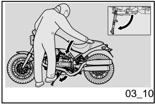
Sopporté (03_10, 03_11)

EL CABALLETE LATERAL Y EL CENTRAL DEBEN GIRAR LIBREMENTE, EN CASO DE SER NECESARIO ENGRASAR LA ARTICULACION.
CABALLETE LATERAL
En el caso de que alguna maniobra (por exemple: el desplazimiento del vehiculo) ha ya provocado el retroceso del caballe,se debe proceder como se indica a continua para volver aponer el vehiculo sobre el mesmo:
Stand (03_10, 03_11)

THE SIDE AND CENTRE STANDS SHOULD TURN SMOOTHLY, GREASE THE JOINT IF NECESSARY.
SIDE STAND
If the stand has been folded up for any manoeuvre (for example, when the vehicle is in motion), place the vehicle on the stand again as follows:
- Grasp the left grip and place your right hand on the rear upper part of
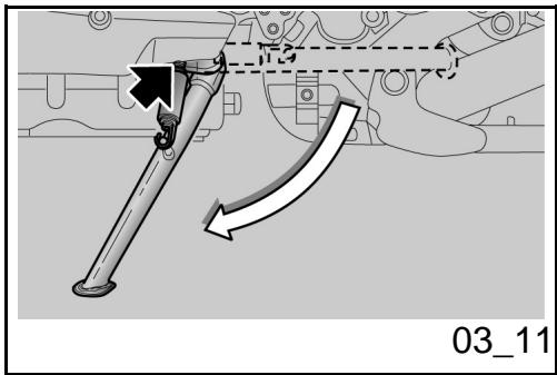
- Tomar el puño izquierdo y apoyar la mano derecha sobre la parte traseira superior del vehiculo.
- Empujar el caballete lateral con el pie decrecho, extendiendo completeness.
- Inclinar el vehiculo hasta que el caballete se apoye en el suejo. Girar el manillar Completely hacer la izquierda
.
the vehicle.
- Push on the side stand with your right foot and lower it completely.
- Lean the vehicle until the stand is resting on the ground.
- Turn the handlebar fully to the left.
CAUTION
MAKE SURE THE VEHICLE IS STABLE.
ATENCLON
ASEGURARSE DE LA ESTABILIDAD DEL VEHICULO.
En el caballete lateral se encuesta un interruptor de seguridad queiene la función de impeder o interruprir el funcionaimiento del motor con la marcha acoplada y el caballete lateral bajo.
A safety switch is installed on the side stand to inhibit ignition or to stop the engine when a gear is engaged and the side stand is lowered.
Sugerencias contra los robos
ATENCLON
SI SE UTILIZA UN DISPOSITIVO DE BLOQUEO DE DISCO, RECORDAR MUY ESPECIALMENTE RETIRARLO ANTES DE CONDICIR EL VEHICULO. LA INOBSERVANCIA DE esta ADVERTENCIA PO
Suggestion to prevent theft
CAUTION
WHEN USING A DISC LOCKING DEVICE, PAY UTMOST ATTENTION TO REMOVE IT BEFORE RIDING. FAILURE TO OBSERVE THIS WARNING MAY CAUSE SERIOUS DAMAGE TO THE BRAKING SYSTEM AND ACCIDENTS WITH CONSEQUENT PHYSICAL INJURIES OR EVEN DEATH.
DRIA CAUSAR SERIOS DANOS A LA INSTALACION DE FRENOS Y PROVOCAR ACCIDENTES CON LOS CONSIGUIENTES DANOS FISICOS O LA MUERTE
NUNCAdehyde de aranque colocada y siemprebloquear el manillar. Aparcar el vehiculo en un lugar seguro, en lo posible en un garaje o en un lugar con vigilancia. Siempre que sea possible,utilizar un segundo dispositivo antirrobo.Controlar que los documents y el impuesto de circulacion esten en order.Encribir los datos personales y el numero de Telefono en esta pagina para facilitar la identificacion del propietario, en caso de que se enquiryel vehiculo,despuesde un robo.
APELLIDO:
NOMBRE:
DIRECCION:
N°
TELEFONICO:
AVVERTENZA
EN MUCHOS CASOS LOS VEHICULOS ROBADOS SE IDENTIFICAN GRACIAS A LOS DATOS INDICADOS EN EL MANUAL
NEVER leave the ignition key in the lock and always use the steering lock. Park the vehicle in a safe place such as a garage or a place with guards. Whenever possible, use an additional antitheft device. Make sure all vehicle documents are in order and the road tax paid. Write down your personal details and telephone number on this page to help identifying the owner in case of vehicle retrieval after a theft.
LAST
NAME:
NAME:
ADDRESS:
TELEPHONE
No:
WARNING
IN MANY CASES, STOLEN VEHICLES CAN BE IDENTIFIED THROUGH DATA INDICATED IN THE USE / MAINTENANCE BOOKLET.
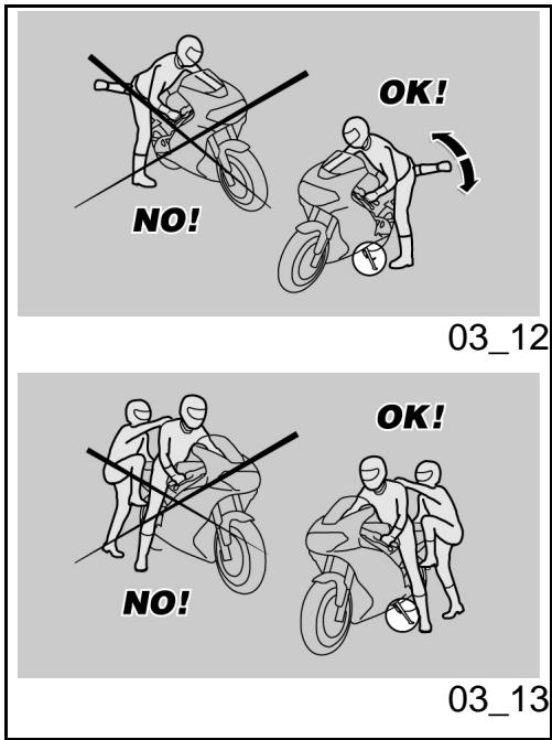
Normas basics de seguridad (03_12, 03_13, 03_14, 03_15, 03_16)
Prestar la maxima atencion a lasindicacionessiguientes porque fueeron redactadas para evitar daños a las personas, a las cosas o alvehiculo,derivados de una possible caida del conductor o del pasajero, o de la caía o vuelco del vehiculo.
Las operaciones de ascenso y descenso del vehiculo deben ser efectuadas con total libertad de movimiento y con las manos libres (de objetivos, casco, guantes o antiparras, auno realizados).
Ascender y descender solo por el lado izquierdo del vehiculo y solo con el caballete lateral bajo.
El caballete fue proyectado para sostener el peso del vehiculo y un minimum de energia, sin conductor ni pasajero.
El ascenso en posicion de conducccion, con el vehiculo posicionado sobre el caballete lateral, solo esta permitido para prevenir una possible caida o vuelco y no prevé la energia del peso del conductor y/o del pasajero.
Basic safety rules (03_12, 03_13, 03_14, 03_15, 03_16)
Strictly follow the instructions compiled below in order to avoid injuring people, damaging property, things and the vehicle in the event the rider or the passenger falls off the vehicle and/or the vehicle falls or overturns.
When getting on and off the vehicle, makesure nothing is restricting your movements;do not hold any objects in your hands (helmet,gloves or goggles not put on).
Always get on and off the vehicle on the left side and with the side stand lowered.
The stand has been designed to support the weight of the vehicle and a minimum load, without the added weight of rider and passenger.
The purpose of the side stand is to prevent the vehicle from falling or overturning while rider and passenger get on the vehicle and get ready to ride; the stand should not be used to support the weight of rider and pas
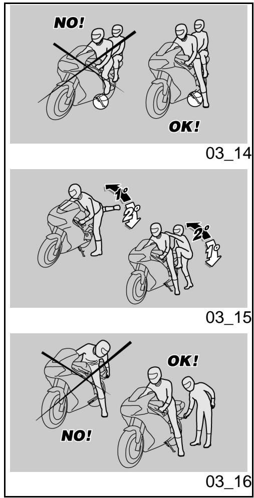
Durante el ascenso y el descenso, el peso del vehiculo可以选择 occasionar un desbalanco con la consiguiente perdida de equilibrio y la posibiliad de una caía o vuelco.
ATENCIón
EL CONDUCTOR ES SIempre EL PRIMERO QUE ASCIERDE AL VEHICULO Y EL ULTIMO EN DESCENDER Y ES EL QUE GOBIERNA EL EQUILIBRIO Y LA ESTABI-LIDAD DURANTE EL ASCENSO O DESCENSO DEL PASAJERO
Por othera parte, el pasajero debeascender y descender del vehiculo con cautela, para no desbalancear el vehiculo y el conductor.
ATENCLON
ES TAREA DEL CONDUCTOR INSTRUIR AL PASAJERO ACERCA DE LA FORMA CORRECTA DE ASCENDER Y DESCENDER DEL VEHICULO.
PARA FACILITAR EL ASCENSO Y EL DESCENSO DEL PASAJERO, EL VEHICULO ESTA PROVISTO DE LOS CORRESPONDIENTES ESTRIBOS REPOSAPIÉS. EL PASAJERO DEBE UTILizar SIEMPRE EL ESTRIBO REPOSAPIÉS IZQUIERDO PARA ASCENDER Y DESCENDER DEL VEHICULO.
NO DESCENDER NI INTENTAR DESCEN- DER DEL VEHICULO SALTANDO O ESTI- RANDO LA PIERNA PARA TOCAR TIE
senger.
While getting on and off, the vehicle may become unstable due to its weight and it may fall or overturn.
CAUTION
THE RIDER MUST GET ON THE VEHICLE FIRST AND GET OFF LAST TO BE ABLE TO CONTROL AND BALANCE THE VEHICLE WHILE THE PASSENGER IS GETTING ON OR OFF THE VEHICLE.
When getting on and off the vehicle, the passenger must move carefully so as not to cause a loss of stability for vehicle and rider.
CAUTION
THE RIDER MUST INSTRUCT THE PASSENGER ON HOW TO GET ON AND OFF THE VEHICLE SAFELY.
THE VEHICLE IS EQUIPPED WITH PASSENGER FOOTRESTS TO FACILITATE GETTING ON OR OFF THE VEHICLE. THE PASSENGER MUST ALWAYS USE THE LEFT FOOTREST TO GET ON AND OFF THE VEHICLE.
NEVER GET OR ATTEMPT TO GET OFF THE VEHICLE BY JUMPING OR STRETCHING YOUR LEG TO REACH THE GROUND. THESE ARE INCORRECT PROCEDURES THAT COMPROMISE VEHICLE STABILITY AND BALANCE.
RRA. EN AMBOS CASOS SE COMPROMETERIA EL EQUILIBRIO Y LA ESTABILIDAD DEL VEHICULO.
ATENCIón
EL EQUIPJA E O LAS COSAS FIJADAS A LA PARTE TRASERA DEL VEHICULO PUEDEN CREAR UN OBSTÁCULO EN EL ASCENSO O DESCENSO DEL MISO.
EN TODOS LOS CASOS PREVER Y EFECTUAR MOVIMIENTOS BIEN CONTROLADOS CON LA PIERNA DERECHA, LA QUE DEBE EVITAR Y SUPERAR LA PARTE TRASERA DEL VEHICULO (COLA O EQUIPASE) SIN DESBALANCEAR EL MISO.
CAUTION
ANY BAGS OR OBJECTS STRAPPED TO THE REAR OF THE VEHICLE CAN REPRESENT AN OBSTACLE WHILE GETTING ON AND OFF.
SWING YOUR RIGHT LEG OVER THE SEAT IN A CONTROLLED MOVEMENT SO AS NOT TO HIT THE REAR PART OF THE VEHICLE (TAIL SECTION OR LUGGAGE) AND COMPROMISE STABILITY.
ASCENSO
- Tomar correctamente el manillar y ascender al vehiculo sin cargar el propio peso en el caballete lateral.
ATENCLON
SI NO LOGRARA APOYAR AMBOS PIES EN EL PISO, APOYAR EL DERECHO (EN EL CASO DE DESBALANCEO EL LADO IZQUIERDO ESTÁ "PROTEGIDO" POR EL CABALLETE LATERAL) Y MANTENER EL IZQUIERDO LISTO PARA APOYARSE.
GETTING ON THE VEHICLE
- Grasp the handlebar correctly and get on the vehicle without resting your weight on the side stand.
CAUTION
IF YOU CAN NOT REACH THE GROUND WITH BOTH FEET WHEN SEATED, PLACE YOUR RIGHT FOOT ON THE GROUND (IF YOU LOSE BALANCE, THE SIDE STAND WILL PREVENT A FALL ON THE LEFT SIDE) AND BE READY TO PUT YOUR LEFT FOOT ON THE GROUND.
-
Apoyar ambos pies en tierra y ende-rezar el vehiculo en posicion de marcha,manteniendolo en equilibrio.
-
Place both feet on the ground, straighten and balance the vehicle keeping it upright in riding position.
ATENCLON
EL CONDUCTOR NO DEBE EXTRAER O INTENTAR EXTRAER LOS ESTRIBOS REPOSAPIES DEL PASAJERO DESDE LA POSICION DE CONDUCCION, PODRIA COMPROMETER EL EQUILIBRIO Y LA ESTABILIDAD DEL VEHICULO.
CAUTION
THE RIDER MUST NOT EXTRACT OR ATTEMPT TO EXTRACT THE PASSENGER FOOTRESTS WHILE SEATED, BECAUSE THIS MIGHT COMPROMISE VEHICLE STABILITY AND BALANCE.
- Hacer que el pasajero extraiga los dos estribos reposapiés pasajero.
- Instruirlo acerca del ascenso al vehiculo.
-
Intervenir con el pie izquierdo en el caballete lateral y hacer que returne completeness.
-
Ask passenger to fold out both passenger footrests.
- Instruct passenger on how to get on the vehicle safely.
- Push the side stand with your left foot to fold it up completely.
DESCENSO
Elegir la zona de aparecido.
Detener el vehiculo.
GETTING OFF THE VEHICLE
- Select a location for parking.
- Stop the vehicle.

CONTROLAR QUE EL TERRENO DE LA ZONA DE APARCAMIENTO ESTÉ DESPEJADO, Y QUE SEA FIRME Y PLANO.

MAKE SURE THE GROUND WHERE YOU HAVE PARKED IS FREE, FIRM AND LEVEL.
-
Con el taco del pie izquierdo, accio
-
With the left shoe heel, lower and
nar en el caballete lateral y extendro completeness.
ATENCIón
SI NO LOGRARA APOYAR AMBOS PIES EN EL PISO, APOYAR EL DERECHO (EN EL CASO DE DESBALANCEO EL LADO IZQUIERDO ESTÁ "PROTEGIDO" POR EL CABALLETE LATERAL) Y MANTENER EL IZQUIERDO LISTO PARA APOYARSE.
extend the side stand completely.
CAUTION
IF YOU CAN NOT REACH THE GROUND WITH BOTH FEET WHEN SEATED, PLACE YOUR RIGHT FOOT ON THE GROUND (IF YOU LOSE BALANCE, THE SIDE STAND WILL PREVENT A FALL ON THE LEFT SIDE) AND BE READY TO PUT YOUR LEFT FOOT ON THE GROUND.
- Apoyar ambos pies en el piso y mantener en equilibrio el vehiculo en posicion de marcha.
-
Instruir al pasajero acerca de la forma correcta dedescending del vehiculo.
-
Place both feet on the ground and balance the vehicle keeping it upright in riding position.
- Instruct the passenger on how to get off the vehicle safely.

PELIGRO DE CAIDA O VUELCO.
ASEGURARSE DE QUE EL PASAJERO HAYA DESCENDIDO DEL VEHICULO. NO CARGAR EL PROPIO PESO EN EL CABALLETELATERAL

RISK OF FALLING AND OVERTURNING.
MAKE SURE THE PASSENGER HAS GOT OFF THE VEHICLE.
DO NOT REST YOUR WEIGHT ON THE SIDE STAND.
-
Inclinar el vehiculo hasta que el caballete apoye en el piso. Tomar correctamente el manillar y descender del vehiculo.
Girar el manillar completeness ha -
Lean the vehicle until the stand is resting on the ground.
- Grasp the handlebar firmly and get off the vehicle.
- Turn the handlebar fully to the left.
cia la izquierda.
- Hacer que el estribo reposapiés pasajero returne a su posición.
ATENCLON

ASEGURARSE DE LA ESTABILIDAD DEL VEHICULO.
- Fold up the passenger footrests.
CAUTION

MAKE SURE THE VEHICLE IS STABLE.
Bellagio


Cap. 04
Elmantimiento
Chap. 04
Maintenance
Premisa
Normalmente las operaciones de mantenimiento ordinario peuvent ser realizadas por el usuario y a veces你可以 tenerce el uso de lapellulación de utilaje especifico y de una cierta preparación技术水平a. En caso deostenimiento periodico, intervención de asistencia o de consultatécnica, dirigirse a un Concesionario Oficial Moto Guzzi, enupon se le garantiza un service esmerado y rápido.
AVVERTENZA
ESTE VEHICULO ESTA PREPARADO PARA IDENTIFICAR EN TIEMPO REAL, EVENTUALES ANOMALIAS DE FUNCIONAMIENTO, MEMORIZADAS POR LA CENTRALITA ELECTRONICA.
CADA VEZ QUE EL CONMUTADOR DE ARRANQUE SE POSICIONA EN "ON", EN EL TABLERO SE ENCIENDE, DURANTE APROXIMADAMENTE TRES SEGUNDOS, EL TESTIGO LED "ALARMA".
Foreword
In general terms, scheduled maintenance can be carried out by the owner; however, some operations may require specific tools and technical training. For periodic maintenance, servicing or technical advice, contact an Official Moto Guzzi Dealer for prompt and accurate service.
WARNING
THIS VEHICLE HAS BEEN PROGRAMMED TO INDICATE IN REAL TIME ANY ACTIVATION FAILURE STORED IN THE ELECTRONIC CONTROL UNIT MEMORY.
ANY TIME THE IGNITION SWITCH IS SET TO "ON", THE "ALARMS" WARNING LIGHT ON THE INSTRUMENT PANEL TURNS ON FOR THREE SECONDS.
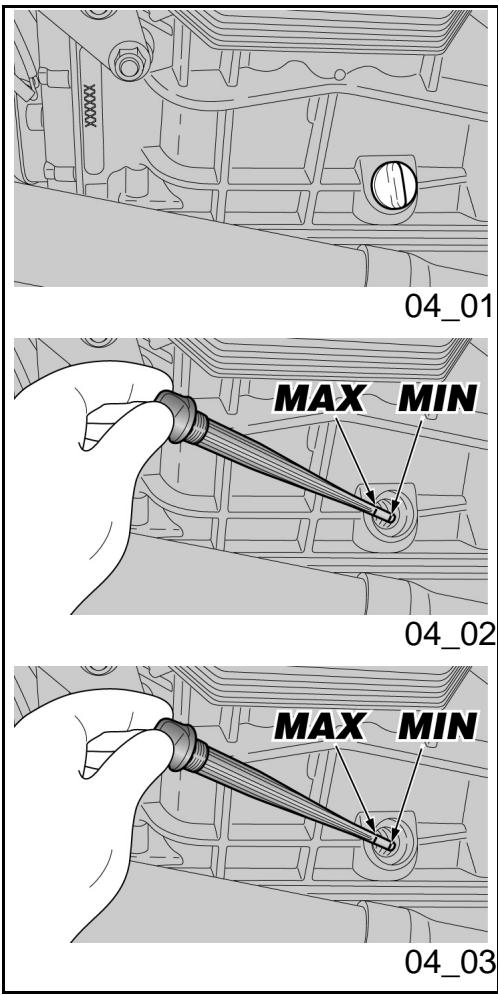
Comprobacion nivel (04_01, 04_02)
Controlar periodicamente el nivel del aceite del motor y sustituirlo cada 10.000 km (6,250 Millas).
Para el control:

EL CONTROL DEL NIVEL DE ACEITE MOTOR DEBE REALIZARSE CON EL MOTOR CALIENTE Y CON LA VARILLA DESENROSCADA..
SI SE EFFECTUA EL CONTROL DEL NIVEL DEL ACEITE CON EL MOTOR EN FRIO, EL ACEITE PODRIA DESCENDER TEMPORALMENTE POR DEBAJO DEL NIVEL "MIN".
LO Dicho NO CONSTITUYE NINGUN PROBLEMA SIempre QUE EN LA PANTALLA NO SE ENCIENDAN EN MODO COMBINADO EL TESTIGO DE ALARMA Y EL ICONO DE PRESION ACEITE DEL MOTOR.
ATENCIón
PARA CALENTAR EL MOTOR Y LLEVAR EL ACEITE A TEMPERATUREA DE FUNCIONAMIENTO, NO HACER FUNCIONAR EL MOTOR EN RALENTI CON EL VEHICULO DETENIDO.
EL PROCEDIMIENTO CORRECTO PREVÉ
Level check (04_01, 04_02)
Check engine oil level regularly, change it every 10000 km (6250 miles).
To check:

THE ENGINE MUST BE WARM TO CHECK OIL LEVEL. DO NOT SCREW IN THE DIP-STICK.
IF YOU CHECK LEVEL WHEN THE ENGINE IS COLD, OIL LEVEL COULD TEMPORARILY DROP BELOW THE "MIN" MARK.
THIS SHOULD NOT BE CONSIDERED A PROBLEM PROVIDED THAT THE ALARM WARNING LIGHT AND THE ENGINE OIL PRESSURE ICON DISPLAY DO NOT TURN ON SIMULTANEOUSLY.
CAUTION
DO NOT LET THE ENGINE IDLE WITH THE VEHICLE AT STAND STILL TO WARM UP THE ENGINE AND OBTAIN THE OPERATING TEMPERATURE OF ENGINE OIL.
OIL IS BEST CHECKED AFTER A TRIP OR AFTER TRAVELLING APPROXIMATELY 15km (10 mi), OUT OF TOWN (ENOUGH TO WARM UP ENGINE OIL TO OPERATING TEMPERATURE).
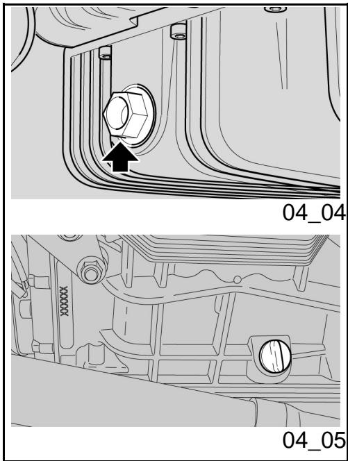
EFFECTUAR EL CONTROL DESPUES DE UN VIAJE O DESPUES DE HABER RECO-RRIDO APROXIMADAMENTE 15 Km (10 mi) FUERA DE LA CIUDAD (SUFICIENTES PARA ELEVAR LA TEMPERATUREA DEL ACEITE DEL MOTOR).
- Parar el motor.
- Mantener el vehiculo en posicion vertical con las dos ruedas apoyadas en el piso.
Desenroscar el tapón de llenado / la varilla de nivel del aceite. -
Limpiar la varilla de nivel del aceite y reinsertarla sin enroscarla.
Extraerla-Newamente y controlar el nivele de aceite.
El nivel es correcto si alcanza aproximamente el nivel "MAX". -
Stop the engine.
- Keep the vehicle upright with the two wheels on the ground.
- Unscrew the filler plug / oil dipstick.
- Clean oil dipstick and replace it without screwing it.
Pull it out again and check the oil level. - The oil level is correct when it is close to the "MAX" mark.
Llenado aceite (04_03)
ATENCIón

NO SOBREPASAR LA MARCA "MAX" NI DESCENDER POR DEBAJO DE LA MARCA "MIN", PARA EVITAR GRAVES DANOS AL MOTOR.
Oil top up (04_03)
CAUTION

DO NOT GO BEYOND THE "MAX" AND BELOW THE "MIN" LEVEL MARK TO AVOID SEVERE ENGINE DAMAGE.
Si es Neededo, restablecer el nivel de aceite del motor:
Desenroscar y quitar el tapón de llénado.

NO AGREGAR ADITIVOS U OTRAS SUSTANCIAS AL ACEITE.
Fill with engine oil as required:
- Unscrew and remove the filler plug.

DO NOT ADD ADDITIVES OR OTHER SUBSTANCES TO THE OIL.
Si se usa un embardo u autre objecto, asegurarse de que estéperfectamente limpio.
ATENCLON
UTILIZAR ACEITE DE BUENA CALIDAD, CON GRADUACION 10W - 60.
When using a funnel or any other element, make sure it is perfectly clean.
CAUTION
USE HIGH-QUALITY 10W - 60 OIL.
-
Llenar restableciendo el nivel solo.
-
Top up oil until reaching the correct level.
Sustitución aceite (04_04, 04_05)

LAS OPERACIONES PARA LA SUSTITUCION DEL ACEITE DEL MOTOR Y DELFILTRO DE ACEITE DEL MOTOR PODRIAN RESULTAR DIFICULTOSAS Y
Oil replacement (04_04, 04_05)

CHANGING ENGINE OIL AND ENGINE OIL FILTER CAN PROVE DIFFICULT IF YOUR ARE INEXPERIENCED.
COMPLEJAS PARA PERSONAS INEXPERTAS.
EN CASO DE NECESIDAD, DIRIGIRSE A UN Concesionario Oficial Moto Guzzi.
SI DESEA EFFECTUARLO PERSONALMENTE, ATENERSE A LAS SIGUIENTES INSTRUCCIONES.
TAKE YOUR VEHICLE TO AN Official Moto Guzzi Dealer IF NECESSARY.
IF YOU WISH TO PERFORM THESE OPERATIONS YOURSELF, FOLLOW THESE INSTRUCTIONS.
Controlar periodicamente el nivel de aceite del motor.
Para la sustitución:
ATENCLON
PARALOGRAR UN MEJOR Y COMPLETO VACIADO,ES NECESARIO QUE EL ACEITE ESTE CALIENTE Y POR LO TANTOMASFLUIDO,CONDICIONQUE SE CONSIGUE DESPUES DE CASI VEINTE MINUTOS DE FUNCIONAMENTO NORMAL.

EL MOTOR CALIENTE TIENE ACEITE CON ALTA TEMPERATUREA, EXTREMAR LOS CUIDADOS PARA NO QUEMARSE DURANTE LAS SIGUIENTES OPERACIONES.
- Colocar un recipiente con capacité adecuada debajo del tapón de drenaje.
Check the engine oil level frequently.
For replacement:
CAUTION
HOT OIL IS MORE FLUID AND WILL DRAIN OUT MORE EASILY AND COMPLETELY; IDEAL TEMPERATURE IS REACHED AFTER THE ENGINE HAS RUN FOR ABOUT TWENTY MINUTES.

OIL BECOMES VERY HOT WHEN THE ENGINE IS HOT; BE CAREFUL NOT TO GET BURNED WHEN CARRYING OUT THE OPERATIONS DESCRIBED BELOW.
- Place a container with suitable capacity under the drainage plug.
- Unscrew and remove the drainage
Desenroscar y quitar el tapón de drenaje.
Desenroscar y quitar el tapón de llenado.
- Drenar ydefer escurrir el aceite durante algunos Minutes dentro del recipientente.
- Controlar y eventualmente sustituir las arandelas de estanqueidad del tapón de drenaje.
- Sacar los residuos metálicos adheridos al imán del tapón de trenaje.
- Enroscar y aparear el tapón de dre-naje.
plug.
- Unscrew and remove the filler cap.
- Drain the oil into the container; allow several minutes for oil to drain out completely.
- Check and, if necessary, replace the drainage plug sealing washers.
- Remove any metal scrap attached to the drainage plug magnet.
- Screw and tighten the drainage plug.

DO NOT DISPOSE OF OIL INTO THE ENVIRONMENT.
DISPOSE OF ENGINE OIL STORED IN A SEATED CONTAINER AND TAKE IT TO YOUR SUPPLIER OR TO THE NEAREST USED OIL RECLAMATION FIRM.

NO ARROJAR EL COMBUSTIBLE AL MEDIO AMBIENTE.
SE RECOMIENDA LLEVARLO AL TALLER DE SERVICIO DONDE HABITUALMENTE SE LO COMPRA O A UN CENTRO DE RECOLECCION DE ACEITES, EN UN RECIPIENTE CERRADO HERMÉTICAMENTE.
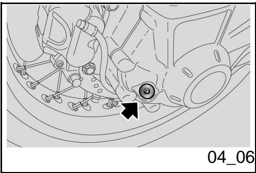
Nivel aceite cardán (04_06)
Controlar periodicamente el nivel de aceite del cardán, sustituirlo en los intervalos previstos en la tabla de mantenimiento programado.
Para el control:
- Mantener el vehístico en posición vertical con las dos ruedas apoyadas en el piso.
Desenroscar y quitar el tapón del nivel. - Contralar a工程技术 del tapón de niven que el aceite toque el orificio. Si el aceite está por debajo del niven indicado se debe proceder alllenado.
Para llenar y eventualmente sustituir el aceite del grupo transmisión cardánica, dirigirse a un Concesionario Oficial Moto Guzzi.
Universal joint oil level (04_06)
Check the cardan shaft oil level regularly; change the oil at the specified intervals according to the scheduled maintenance table
To check:
- Keep the vehicle upright with the two wheels on the ground.
- Unscrew and remove the level plug.
- Check that the oil level is on the rim of the hole of the level plug. Top-up if oil is below the specified level.
To top-up or change the oil in the cardan shaft transmission unit, contact an Official Moto Guzzi Dealer.
Nivel aceite cambio
- Para el control, el llenado y la sustitución del aceite del cambio, dirigir-se a un Concesionario Oficial Moto Guzzi.
Gearbox oil level
- To check, top-up and change gearbox oil, contact an Official Moto Guzzi Dealer.
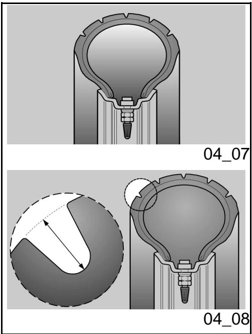
Neumáticos (04_07, 04_08)
Elmodelodispone de neumatico concamara.
ATENCIón
CONTROLAR PERIODICAMENTE LA PRESION DE INFLADO DE LOS NEUMATICOS A TEMPERATURA AMBIENTE. SI LOS NEUMATICOS ESTAN CALIENTES, LA MEDICION NO SERA CORRECTA. REALIZAR LA MEDICION ESPECIALMENTE ANTES Y DESPUISES DE UN VIAJE LARGO. SI LA PRESION DE INFLADO ES DEMASIADO ALTA, LAS ASPEREZAS DEL TERRENO NO SE AMORTIGUARAN Y POR LOTANTO SE TRANSMITIRAN AL MANILLAR COMPROMETIENDO DE esta MANERA EL CONFORT EN LA MARCHA Y REDUCIENDO TAMBIEN EL AGARRE A LA CARREtera EN LAS CURVAS.
EN CAMBIO, SI LA PRESION DE INFLADO ES INSUFICIENTE, LOS FLANCOS DE LOS NEUMÁTICOS TRABAJARAN DEMASIADO Y PODRÍA PRODUCIRSE UN DESPLAZAMIENTO DE LA GOMA SOBRE LA LLANTA, O BIEN SU SEPARACION, CON LA CONSIGUIENTE PÉRDIDA DE CONTROL DEL VEHÍCULO.
EN CASO DE FRENADAS BRUSCAS, LOS NEUMÁTICOS PODRIAN SALIRSE DE LAS LLANTAS.
Y POR ÚLTIMO, EL VEHÍCULO PODRIA DERRAPAR EN CURVAS.
Tyres (04_07, 04_08)
The model is provided with tires with tube.
CAUTION
CHECK TYRE INFLATION PRESSURE REGULARLY AT AMBIENT TEMPERATURE. THE MEASUREMENT MAY BE INCORRECT IF TYRES ARE WARM. CHECK TYRE PRESSURE MAINLY BEFORE AND AFTER A LONG TRIP. IF TYRE PRESSURE IS TOO HIGH, THE SURFACE UNEVENNESS IS NOT CUSHIONED AND IS SENT TO THE HANDLEBAR, THUS REDUCING COMFORT, GRIP AND STABILITY SPECIALLY WHEN CORNERING.
ON THE OTHER HAND, AN UNDER-INFLATED TYRE CAUSES THE CONTACT PATCH TO INCLUDE A LARGER PORTION OF THE TYRE SIDE WALLS. IF SO, THE TYRE MIGHT SLIP ON OR GET DETACHED FROM THE RIM, RESULTING IN LOSS OF CONTROL OVER THE VEHICLE.
IN CASE OF SHARP BRAKING, TYRES CAN EVEN GET OFF THE RIMS.
EVENTUALLY THE VEHICLE MIGHT SKID IN A BEND..
INSPECT THREAD SURFACE AND CHECK IT FOR WEAR. BADLY WORN TYRES ADVERSELY AFFECT TRACTION AND HANDLING.
SOME TYRE TYPES HOMOLOGATED FOR THIS VEHICLE FEATURE WEAR IN
CONTROLAR EL ESTADO SUPERFICIAL Y EL DESGASTE, YA QUE UN ESTADO DEFICIENTE DE LOS NEUMÁTICOS COMPROMETERIA LA ADHERENCIA EN LA CARREtera Y LA MANIOCRABILIDAD DEL VEHÍCULO.
ALGUNOS TIPOS DE NEUMÁTICOS, HOMOLOGADOS PARA ESTE VEHÍCULO, POSEEN INDICadores DE DESGASTE.
EXISTEN VARIOS TIPOS DE INDICADORES DE DESGASTE. INFORMARSE CONEL PROPIO REVENDEDOR ACERCA DELAS MODALIDADES DE CONTROL DESGASTE.
CONTROLLER VISUALMENTE EL CONSUMO DE LOS NEUMÁTICOS, SI ESTÁN DESGASTADOS, SUSTITUIRLOS.
SI LOS NEUMÁTICOS ESTÁN VIEJOS, AUNQUE NO COMPLETAMENTE DESGASTADOS, PUEDEN ENDURECERSE Y NO GARANTIZAR LA ADHERENCIA EN CARREtera. EN Este CASES SUSTITUIROS. HACER SUSTITUIR EL NEUMÁTICO SI ESTÁ GASTADO O SI UNA EVENTUAL PERFORACION EN LA ZONA DE LA BANDA DE RODADURA POSEE UNA DIMENSION MAYOR A 5 mm (0.197 in).
DESPUÉS DE REPARAR UN NEUMÁTICO, SE DEBE PROCEDER AL EQUILIBRADO DE LAS RUELAS.
USAR EXCLUSIVAMENTE NEUMÁTICOS CON LAS DIMENSIONES INDICADAS
DICATORS.
THERE ARE DIFFERENT TYPES OF WEAR INDICATORS. CONSULT YOUR DEALER ON METHODS TO CHECK FOR WEAR.
CARRY OUT A VISUAL INSPECTION FOR TYRE WEAR AND TEAR, REPLACE TYRES WHEN WORN.
WHEN TYRES ARE OLD, THE MATERIAL MAY HARDEN AND NOT PROVIDE ADEQUATE GRIP, EVEN IF TYRES ARE STILL WITHIN THE WEAR LIMIT. REPLACE TYRES IF THIS OCCURS. REPLACE THE TYRE IF IT IS WORN OR IF THERE IS A PUNCTURE LARGER THAN 5 mm (0.197 in) IN THE TREAD AREA.
WHEEL MUST BE BALANCED AFTER A TYRE IS MENDED.
USE ONLY TYRE SIZES INDICATED BY THE MANUFACTURER. DO NOT FIT TYRES WITH INNER TUBES ON RIMS FOR TUBELESS TYRES OR VICE VERSA. CHECK THAT THE INFLATION VALVES HAVE THEIR CAPS FITTED TO AVOID UNEXPECTED FLAT TYRES.
REPLACEMENT, REPAIR, MAINTENANCE AND BALANCING OPERATIONS ARE HIGHLY IMPORTANT AND SO THEY SHOULD BE CARRIED OUT USING THE SPECIFIC TOOLS AND WITH THE ADEQUATE KNOWLEDGE. HAVE YOUR TYRES AND WHEELS SERVICED AT AN
POR LA EMPRESA. NO INSTALAR NEUMÁTICOS DEL TIPO CON CÁMARA DE AIRE EN LLANTAS PARA NEUMÁTICOS TUBELESS Y VICEVERSA. CONTROLAR QUE LAS VALVULAS DE INFLADO POSEAN LAS TAPAS PARA EVITAR LA PÉRDIDA DE PRESION DE LOS NEUMÁTICOS.
LAS OPERACIONES DE SUSTITUCION, REPARACIOn, MANTENIMIENTO Y EQUILIBRADO SON MUY IMPORTANTES: PARA REALIZARLAS SE DEBE CONTAR CON LAS HERRAMIENTAS ADECUADAS Y CON LA EXPERIENCIA NECESARIA. POR Este MOTIVO SE RECOMIENDA DIRIGIRSE A UN CONCESSIONARIO OFICIAL O A UN TALLER DE NEUMATICOS ESPECIALIZADO PARA EJECUTAR LAS OPERaciones ANTERIORES.
SI LOS NEUMÁTICOS SON NUEVOS, PUCDEN ESTAR RECURBIERTOS POR UNA CAPA RESBALADIZA: CONDU CIR CON CAUTELA DURANTE LOS PRIMEROS KILÔMETROS. NO APLICAR NINGUN LÍQUIDO INADECUADO A LOS NEUMÁTICOS.
SI LOS NEUMÁTICOS ESTÁN VIEJOS, AUNQUE NO COMPLETAMENTE DESGASTADOS, PUEDEN ENDURECERSE Y NO GARANTIZAR. LA ADHERENCIÀ EN CARREtera.
EN Este CASO, SUSTITUIR LOS NEUMÁTICOS.
OFFICIAL DEALER OR A SPECIALISED TYRE WORKSHOP.
NEW TYRES MAY BE COATED WITH AN OILY FILM: RIDE WITH CAUTION DURING THE FIRST KILOMETRES. DO NOT APPLY UNSUITABLE LIQUIDS ON TYRES.
WHEN TYRES ARE OLD, THE MATERIAL MAY HARDEN AND NOT PROVIDE ADEQUATE GRIP, EVEN IF TYRES ARE STILL WITHIN THE WEAR LIMIT. TYRE GRIP
IF THIS IS THE CASE, REPLACE THE TYRES.
Limineto de profundidad de la bandada derodadura:
delantera y trasera 2 mm (0.079 in) (USA 3 mm) (USA 0.118 in) y en ningún caso inferior a lo prescritto por la legislación vigente en el País de uso del vehúculo.
Minimum tread depth:
front and rear 2 mm (0.079 in) (USA 3 mm) (USA 0.118 in), and not less than required by regulations in force in the country where the vehicle is used.
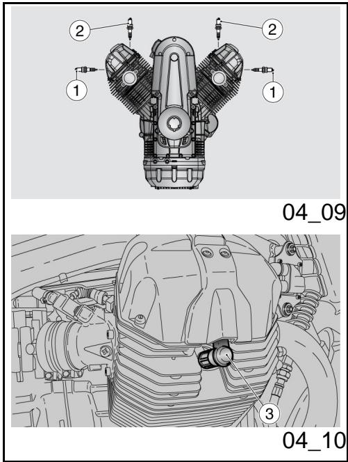
Desmontaje bujía (04_09, 04_10, 04_11, 04_12, 04_13)

LAS SIGUIENTES INSTRUCCIONES SE REFIEREN UNICAMENTE A LAS BUJIAS EXTERNAS (1). LA MOTOCICLETA TAMBIEN ESTÁ EQUIPADA CON DOS BUJIAS INTERIORES (2); PARA SUSTITUIRLAS DIRIGIRSE A UN Concessionario Oficial Moto Guzzi.

SUSTITUIR SIEMPRE AMBAS BUJIAS EXTERNAS (1) INCLUSO SI UNA SOLA DEELLAS REQUIERE SER SUSTITUIDA.
Para extraerla:
Spark plug dismantlement (04_09, 04_10, 04_11, 04_12, 04_13)

THE FOLLOWING INSTRUCTIONS APPLY ONLY TO OUTER SPARK PLUGS (1). THE MOTORCYCLE IS EQUIPPED WITH TWO INNER SPARK PLUGS (2); CONTACT AN Official Moto Guzzi Dealer TO HAVE THEM REPLACED.

ALWAYS REPLACE BOTH OUTER SPARK PLUGS (1), EVEN IF ONLY ONE NEEDS REPLACING.
For removal:
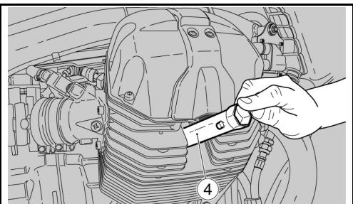
04_11
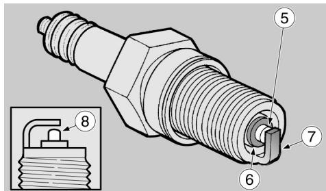
04_12
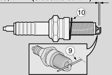
0,6 - 0,7 mm (0.023 - 0.027 in)
04_13
- Quitar la pipeta (3) de la bujía.
- Eliminar toda suciedad de la base de la bujía.
- Introducir en la bujía la llave suministrada en dotación con el kit de herramrientas.
- Introducir en el alojamente hexagonal de la llave para la bujía, la llave (4) suministrada en dotación con el kit de herramrientas.
Desenroscar la bujía y extraerla de su alojamento, prestando atencion a que no ingrese polvo u otheras sus-. tancias en el cilindro.
Para el control y la limpieza:

PARALIMPIEZA NO UTILizar CEPILLOS METÁLICOS Y/O PRODUCTOS ABRASIVOS, SINO EXCLUSIVAMENTE UN CHORRO DE AGUA A PRESION.
Leyenda:
- electrodeo central (5);
-aislante (6); - electrodo lateral (7).
-
Controlar que los electrodos y el aislante de la bujía no presenten depósitos de carbono o MARCAS de corrosión, si fuera NEEDario limpiar
-
Remove the spark plug tube (3).
- Remove any trace of dirt from the spark plug base.
- Fit the special spanner supplied in the tool kit to the spark plug.
- Insert the key (4) supplied in the tool kit into the hexagonal head of the spark plug spanner.
- Unscrew the spark plug and remove it from its seat, making sure no dust or dirt falls into the cylinder.
Checks and cleaning:

DO NOT USE METAL BRUSHES AND/OR ABRASIVE PRODUCTS TO CLEAN THE SPARK PLUGS; USE ONLY A BLAST OF COMPRESSED AIR.
Key:
- central electrode (5);
- insulator (6);
- side electrode (7);
- Check that the spark plug electrodes and insulator do not show traces of carbon deposits and of corrosion. If required, clean them
con unchorro de agua a presión.
LaBJIaBeSusituiduCuando presenta: grieras en elaislante,electrodos corroidos, depotos excessivos o electrodo central (5) con la cabeza redondeada (8).
- Controlar la distancia entre los electrodos con un calibre de espaces del tipo con hilo (9).
ATENCIón

NO INTENTAR DE NINGUNA MANERA RESTABLECER LA DISTANCIA ENTRE LOS ELECTRODOS.
La distancia entre los electrodos debe ser de 0,6 - 0,7 mm. (0.023 - 0.027 pulgadas): si fuera diferente, sustituir la bujía.
- Asegurarse que la arandela (10) está en buena conditiones.
Para la instalación:
- Con la arandela (10) montada, enroscar a mano la bucía para evitar daßar el roscado.
- Apretar con la llave en dotación del kit de herramrientas girando 1/2 vuelta cada bucía para aplterla arandela.
Par de apriete de la bujía: 20 Nm (2 kgm).
using a compressed air jet.
Replace the spark plug if its insulator is cracked, the electrodes show signs of corrosion or excessive deposits or the top (8) of the central electrode (5) gets rounded.
- Check the electrode gap with a feeler thickness gauge (9).
CAUTION

DO NOT ATTEMPT TO READJUST THE ELECTRODE GAP.
The electrode gap should be between 0.6 - 0.7 mm (0.023 - 0.027 in). Replace the spark plug if the gap is different.
Make sure that the washer (10) is in good conditions.
Installation:
- Once the washer (10) is fitted, manually screw the spark plug to avoid damaging the thread.
- Tighten it using the spanner supplied in the tool kit, make each spark plug complete 1/2 of a turn to press the washer.
Spark plug tightening torque: 20 Nm (2
ATENCLON
LA BUJIA DEBE ESTAR BIEN ENROSCADA, DE OTRA MANERA EL MOTOR PODRIA SOBRECALENTARSE Y DANARSE GRAVEMENTE.
USART SOLAMENTE BUJIAS DEL TIPO RECOMENDADO; EN CASO CONTRARIOSE PODRIAN COMPROMETER LAS PRESTACIONES Y LA DURACION DEL MOTOR.
kgm).
CAUTION
TIGHTEN THE SPARK PLUG CORRECTLY. OTHERWISE, THE ENGINE MAY OVERHEAT AND GET IRRETRIEVABLE DAMAGED.
USE ONLY THE RECOMMENDED TYPE OF SPARK PLUG, OTHERWISE, THE ENGINE DURATION AND PERFORMANCE COULD BE COMPROMISED.
-
Introducir correctamente la pipeta de la bucía, de manière que no se suele con las vibraciones del motor.
-
Place the spark plug tube correctly so that it does not get detached due to engine vibrations.
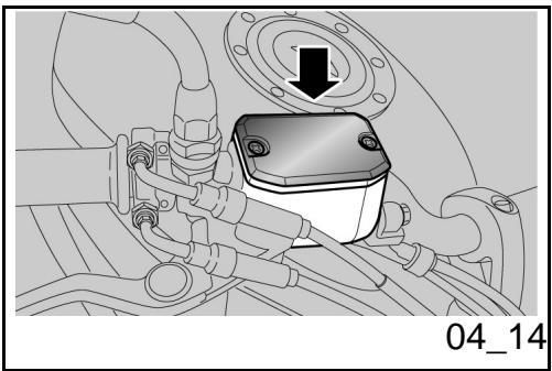
Control nivel aceite frenos (04_14, 04_15)
Control liquido de frenos
- Solamente por el depóstito del frenoTRSERO, SACAR el asiento y el carenado lateral derecho
- Mantener el vehístico en posición vertical deundry que el liquido del deposito que de paralelo al tapón.
- Controlar que el liquido contenido en el deposito supere la referencia "MIN":
Checking the brake oil level (04_14, 04_15)
Brake fluid check
- Only for the rear brake reservoir, remove the saddle and the right side fairing
- Place the vehicle upright so that the fluid in the reservoir is parallel to the cap.
Make sure that the fluid level in the reservoir is above the "MIN" reference mark:
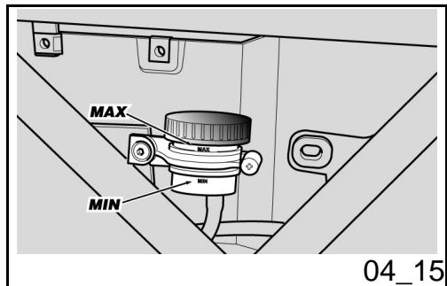
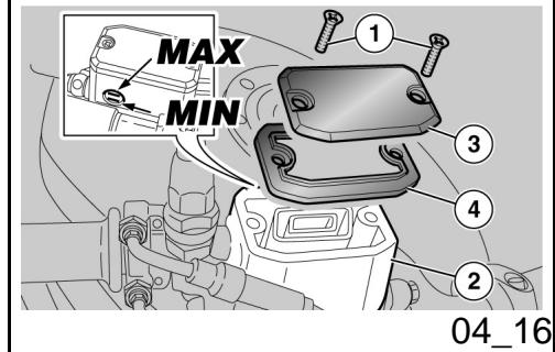
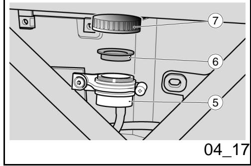
MIN=nivel minimo.
M = nivel maximal
Si el liquido no llega por lo menos a la referencia "Mín":
- Controller el desgaste de las pastillas de frenos, y del disco.
- Si las pastillas y/o el disco no se deben sustituir, realizar el llenado.
Llenado liquido circuito de frenos (04_16, 04_17)

PELIGRO DE PÉRDIDA DEL LÍQUIDO DE FRENOS. NO ACCIONAR LA PALANCA DEL FRENO SI EL TAPON DEL DEPOSITO DEL LÍQUIDO DE FRENOS ESTA FLOJO O FALTARA.

EVITAR LA EXPOSICION PROLONGADA DEL LÍQUIDO DE FRENOS AL AIRE. EL LÍQUIDO DE FRENOS ES HIGROSCOPICO, POR LO TANTO EN CONTACTO CON EL AIRE ABSORBE HUMEDAD. EL DEPOsITO DEL LÍQUIDO DE FRENOS DEBE PERMANECER ABIERTO SOLO EL TIEMPO NECESARIO PARA EFFECTUAR EL LLENADO.
MIN = minimum level
MAX = maximum level
If the fluid does not reach at least the "MIN" reference mark:
- Check brake pads and disc for wear.
- If the pads and/or the disc do not need replacing, top-up the fluid.
Braking system fluid top up (04_16, 04_17)

RISK OF BRAKE FLUID SPILLING. DO NOT OPERATE THE BRAKE LEVER IF THE BRAKE FLUID RESERVOIR CAP IS LOOSE OR HAS BEEN REMOVED.

AVOID PROLONGED AIR EXPOSURE OF THE BRAKE FLUID. BRAKE FLUID IS HYGROSCOPIC AND ABSORBS MOISTURE WHEN IN CONTACT WITH AIR. LEAVE THE BRAKE FLUID RESERVOIR OPEN ONLY FOR THE TIME NEEDED TO COMPLETE THE TOPPING-UP PROCEDURE.

TO AVOID SPILLING BRAKE FLUID

PARA EVITAR DERRAMAR EL LIQUIDO DE LA INSTALLACION DE FRENOS DURANTE EL LLENADO, SE RECOMIENDAMANTENERLO EN EL DEPOSITO, PARALELO AL BORDE DEL Mismo (EN POSICION HORIZONTAL). NO AGREGAR ADITIVOS U OTRAS SUSTANCIAS AL LIQUIDO. SI SE UTILIZA UN EMBUDO U OTRO OBJECTO, ASEGURARSE DE QUE ESTE PERFECTAMENTE LIMPIO.
WHILE TOPPING-UP, KEEP THE FLUID LEVEL IN THE RESERVOIR PARALLEL TO THE RESERVOIR EDGE (IN HORIZONTAL POSITION). DO NOT ADD ADDITIVES OR OTHER SUBSTANCES TO THE FLUID. IF A FUNNEL OR ANY OTHER ELEMENT IS USED, MAKE SURE THAT IT IS PERFECTLY CLEAN.
Instalación de frenos delantera
- Utilizando un destornillador corto de cruz, desenroscar los tornillos (1) del deposito de liquido de la instalacion de frenos delantera (2).
Levantar y extraer la tapa (3) con los tornillos (1). - Retirar la junta (4).
- Llenar el deposito (2) con el liquido de frenos acontejado, hasta alcanzar el nivel solo compendio entre las dos referencias "MIN" y "MAX".
Instalación de frenos trasera
Desenroscar y retirar el tapón (6).
- Retirar la junta (7).
- Llenar el deposito (5) con el liquido de frenos acontejado, hasta alcanzar el nivel solo compendio entre las dos referencias "MIN" y "MAX".
Front braking system
- Use a short crosshead screwdriver to undo the screws (1) of the front braking system (2) fluid reservoir.
- Lift and remove the cover (3) and screws (1) as well.
- Remove the gasket (4).
- Fill the reservoir (2) with recommended brake fluid up to the correct level, which is between the two "MIN" and "MAX" reference marks.
Rear braking system
- Unscrew and remove the cap (6).
- Remove the gasket (7).
- Fill the reservoir (5) with recommended brake fluid up to the correct level, which is between the two "MIN" and "MAX" reference marks.

DURANTE EL LLENADO, EVITAR DAR VUELTA EL DEPOSITO DE LÍQUIDO DE LA INSTALLACION DE FRENOS, Aún CON EL TAPON CERRADO. PODRIA ENTRAR AIRE EN EL CIRCUito, CON EL CONSIGUIENTE MALFUNCTIONAMIENTO DE LA INSTALLACION DE FRENOS.

DURANTE EL LLENADO NO SUPERAR EL NIVEL "MÁX".
SÓLO SE DEBE LLENAR HASTA EL NIVEL "MÁX" SI LAS PASTILLAS SON NUEVAS. SE RECOMienda NO LLENAR HASTA EL NIVEL "MÁX" SI LAS PASTILLAS ESTÁN DESGASTADAS, YA QUE ESTO PROVOCARIA LA PÉRDIDA DE LÍQUIDO EN CASO DE SUSTITUCION DE LAS PASTILLAS DE FRENO.
CONTROLAR LA EFICIENCY DEL FRENADO. EN CASEO DE UNA CARRERA EXCESIVA DE LA PALANCA DE FRENO O DE UNA PÉRDIDA DE EFICIENCY EN LA INSTALLACION DE FRENOS, DIRIGIRSE A UN CONCESSIONARIO OFICIAL MOTO GUZZI, YA QUE PODRÍA SER NECESA RIO PURGAR EL AIRE DE LA INSTALA- CION.

WHEN TOPPING-UP DO NOT OVERTURN THE BRAKE FLUID RESERVOIR, EVEN IF THE CAP IS CLOSED. THIS MAY CAUSE AIR ENTERING THE CIRCUIT, WHICH WILL RESULT IN A MALFUNCTIONING BRAKING SYSTEM.

DO NOT EXCEED THE "MAX" LEVEL MARK WHEN TOPPING-UP.
TOP UP TO THE "MAX" LEVEL MARK ONLY WHEN BRAKE PADS ARE NEW. IT IS ADVISIBLE NOT TO TOP UP TO THE "MAX" LEVEL MARK WHEN THE BRAKE PADS ARE WORN BECAUSE YOU RISK SPILLING FLUID WHEN REPLACING THE BRAKE PADS.
CHECK BRAKING EFFICIENCY. IN CASE OF EXCESSIVE TRAVEL OF THE BRAKE LEVER OR POOR PERFORMANCE OF THE BRAKING SYSTEM, TAKE YOUR SCOOTER TO AN OFFICIAL MOTO GUZZI DEALER, AS IT MAY BE NECESSARY TO PURGE AIR IN THE SYSTEM.
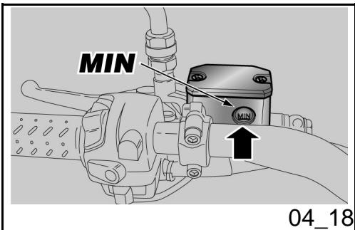
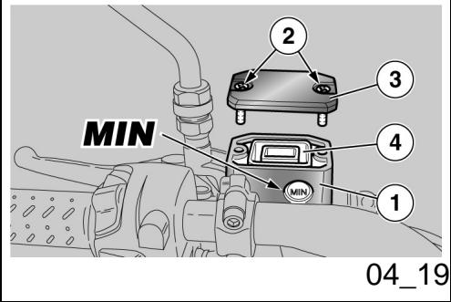
Control liquido embrague (04_18)
- Posicionar el vehiculo en el caballete.
Girar el manillar parcialmente hacer la referencia de manos tal que el liquido contenido en el deposito del liquido del embrague se incluye paralelo al borde del deposito del liquido del embrague. - Controlar que el liquido contenido en el deposito supere la referencia "MIN"
MIN = nivel minimo.
M = nivel maximo.
Si el liquido no alcanza por lo menos la referencia "Mín", proceder al llenado.
Reposicion liquido embrague (04_19)
- Utilizando un destornillador en cruz desenroscar los dos tornillos (2) del deposito liquido del embrague (1).
Levantar y quitar la tapa (3) con los tornillos (2).
Extraer la junta (4).
Llenar el deposito con el liquido del embarque hasta cubrir Completely el visor que corresponde al niveau máximo.
Checking clutch fluid (04_18)
- Place the vehicle on its stand.
- Turn the handlebar partially to the right, so that the fluid inside the clutch fluid reservoir is parallel to the reservoir edge.
Make sure the fluid level is above the "MIN" mark.
MIN = minimum level
MAX = maximum level
Top up if the fluid does not reach at least the "MIN" reference mark.
Topping up clutch fluid (04_19)
- Undo the two screws (2) of the clutch fluid reservoir (1) using a crosshead screwdriver.
- Lift and remove the cover (3) and also the screws (2).
- Remove the gasket (4).
Top up the reservoir with clutch oil until fluid completely covers the sight glass corresponding to the maximum level.

PARA EVITAR DERRAMAR EL LIQUIDO DURANTE EL LLENADO, SE RECOMIENDA MANTENER EL LIQUIDO EN EL DEPOSITO PARALELO AL BORDE DEL DEPOSITO (EN POSICION HORIZONTAL).
NO AGREGAR ADITIVOS NI OTRAS SUSTANCIAS AL LIQUIDO.
SI SE USA UN EMBUDO U OTRO OBJECTO, ASEGURARSE DE QUE ESTÉ PERFECTAMENTE LIMPIO.

PELIGRO DE DERRAME DEL LIQUIDO DEL EMBRAGUE. NO ACCIONAR LA PALANCA DEL EMBRAGUE SI EL TAPON DEL DEPOSITO DEL LIQUIDO ESTA FLOJO O FALTARA.
COLOCAR UN PANO DEBAJO DEL DEPOSITO DEL LIQUIDO DEL EMBRAGUE COMO MEDIDA PREVENTIVA POR EVENTUALES PÉRDIDAS DEL LIQUIDO.

EVITAR LA EXPOSICION PROLONGADA AL AIRE DEL LIQUIDO MANDO EMBRAQUE.
EL LIQUIDO DEL EMBRAGUE ES HI

TO AVOID SPILLING FLUID WHILE TOPPING-UP, KEEP THE TANK PARALLEL TO THE RESERVOIR EDGE (IN HORIZONTAL POSITION).
DO NOT ADD ADDITIVES OR OTHER SUBSTANCES TO THE FLUID.
WHEN USING A FUNNEL OR ANY OTHER ELEMENT, MAKE SURE IT IS PERFECTLY CLEAN.

RISK OF CLUTCH FLUID SPILLING. DO NOT OPERATE THE CLUTCH LEVER IF THE FUEL RESERVOIR CAP IS LOOSE OR HAS BEEN REMOVED.
PLACE A CLOTH UNDER THE CLUTCH RESERVOIR TO PROTECT IT FROM ANY FLUID SPILLING.

AVOID PROLONGED AIR EXPOSURE OF THE CLUTCH CONTROL FLUID.
THE CLUTCH FLUID IS HYGROSCOPIC AND ABSORBS MOISTURE WHEN IN CONTACT WITH AIR.
GROSCOPICO Y EN CONTACTO CON EL AIRE ABSORBE LA HUMEDAD.
EL DEPOSITO DEL LIQUIDO MANDO EMBRAGUE DEBE PERMANECER ABIERTOSOLO EL TIEMPO NECESARIO PARA EFFECTUAR EL LLENADO.
LEAVE THE CLUTCH CONTROL FLUID RESERVOIR OPEN ONLY FOR THE TIME NEEDED TO COMPLETE THE TOPPING UP PROCEDURE.
- Colocar correctamente la junta (4) en su alojamento.
- Colocar la tapa (3).
-
Enroscar y aparear los tornillos (2).
-
Refit the gasket (4) correctly in its seat.
- Refit the cover (3).
Screw and tighten the screws (2).

DURANTE EL LLENADO NO SUPERAR EL NIVEL "MAX".
CONTROLLER EL BUEN FUNCIONAMIENTO DEL EMBRAGUE.
SI LA PALANCA DE MANDO DEL EMBRAGUE REALIZARA UNA EXCESIVA CARRERA EN VACIO O EN EL CASO DE UNA PÉRDIDA DE EFICIENCY EN LA INSTALLACION DEL EMBRAGUE, DIRIGIRSE A UN Concesionario Oficial Moto Guzzi, DADO QUE PODRIA SER NECESARIO EFFECTUAR LA PURGA DEL AIRE DE LA INSTALLACION.

DO NOT EXCEED THE "MAX" LEVEL MARK WHEN TOPPING-UP.
CHECK THE CLUTCH FOR PROPER OPERATION.
IN THE EVENT OF EXCESSIVE CLUTCH LEVER EMPTY TRAVEL OR POOR CLUTCH OPERATION, TAKE YOUR VEHICLE TO AN Official Moto Guzzi Dealer, AS THE SYSTEM MAY NEED BLEEDING.
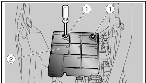
04_20
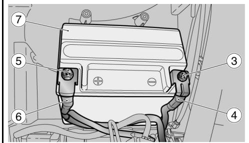
04_21
Puesta en servicios de una baterianea (04_20, 04_21)
- Asegurarse de que el conmutador de encendido se enquiryra en "OFF".
- Quitar el asiento del piloto.
Desenroscar los dos tornillos (1) y desplazar la taps (2).
Desenroscar y qutar el tornillo (3) del borne negativo (-). - Desplazar lateralmente el cable negativo (4).
Desenroscar y qutar el tornillo (5) del borne positivo (+). - Desplazar lateralmente el cable positivo (6).
- Tomar con fuerza la batería (7) y sacarla de su alojamento levantándola.
- Colocar la bateria sobre una superficie plana, en un lugar fresco y seco.
- Volver a colocar el asiento del piloto.
Para instalar una nuevo bateria ejectar las operaciones descritas en sentido inverso.
ATENCLON
PARAVOLVERAMONTARLA,PRIMERO SEDEBECONECTARELCABLEENEL BORNEPOSITIVE (+) YLUEGOELDEL
Use of a new battery (04_20, 04_21)
Make sure the ignition switch is set to "OFF".
- Remove the rider saddle.
- Unscrew the two screws (1) and remove the cover (2).
- Loosen and remove the screw (3) of the negative terminal (-).
- Move the negative leads (4) aside.
- Loosen and remove the screws (5) of the positive terminal (+).
- Move the positive leads (6) aside.
- Hold the battery (7) firmly and lift it out of its compartment.
- Put the battery away on a level surface, in a cool and dry place.
- Refit the rider seat.
To install a new battery follow the operations described above but in reverse order.
CAUTION
UPON REFITTING, CONNECT THE LEAD TO THE POSITIVE TERMINAL (+) FIRST AND AFTERWARDS THE LEAD TO THE NEGATIVE TERMINAL (-) .

CHECK THAT THE BATTERY LEADS AND TERMINALS ARE:
- IN GOOD CONDITION (NOT CORRODED
BORNE NEGATIVO (-).

CONTROLLER QUE LOS TERMINALES DE LOS CABLES Y LOS BORNES DE LA BATERIA SE ENCUESTREN:
EN BUENAS CONDICIONES (Y NO CORROÍDOS O CUBIERTOS DE DEPOSITO);
- CUBIERTOS CON GRASA NEUTRA O CON VASELINA.
Comprobacion del nivel del electrolito
AVVERTENZA
ESTE VEHICULO ESTA EQUIPADO CON UNA BATERIA QUE NO REQUIERE MANTENIMIENTO Y NO REQUIERE NINGUN TIPO DE INTERVENTION, SINO UN ESPORÁDICO CONTROL Y UNA EVENTUAL RECARGA.
OR COVERED BY DEPOSITS);
- COVERED BY NEUTRAL GREASE OR PETROLEUM JELLY.
Checking the electrolyte level
WARNING
THIS VEHICLE IS FITTED WITH A MAIN- TENANCE-FREE BATTERY AND DOES NOT NEED ANY INTERVENTION, EXCEPT FOR SPORADIC CHECKS AND RE- CHARGE.
Recarga bateria
Sacar la batería.
- Preparar un cargador de bateria inadeado.
- Predisponer el cargador de bateria para el tipo de recarga indicada
- Conectarla al cargador de bateria.
Charging the battery
- Remove the battery.
Get an adequate battery charger. - Set the battery charger for the recharge type indicated.
- Connect the battery to the battery charger.
ATENCIón

DURANTE LA RECARGA O USO, VENTILAR ADECUADAMENTE EL LOCAL, EVITAR LA INHALACION DE LOS GASES EMITIDOS DURANTE LA RECARGA DE LA BATERIA.
CAUTION

WHEN RECHARGING OR USING THE BATTERY, BE CAREFUL TO HAVE THE ROOM ADEQUATELY AIRED. DO NOT BREATH GASES RELEASED WHEN THE BATTERY IS RECHARGING.
Encender el cargador de baterías.
Characteristicas Tecnicas
MODALIDAD DE RECARGA
Recarga - Normal
Corriente Eléctrica - 1,8 A
Tiempo - 8-10 horas
Switch on the battery charger.
Characteristic
RECHARGE MODES:
Recharge - Ordinary
Electric Current - 1.8A
Time - 8-10 hours
Larga inactividad

SI EL VEHICULO PERMANECE INACTIVO DURANTE MÁS DE VEINTE DIAS, DESCONECTAR LOS FUSIBLES DE 30 A PARA EVITAR LA DEGRADACION DE LA BATERIA DEBIDA AL CONSUMO DE CORRIENTE DEL ORDENADOR MULTIFUNCIÑ.
Long periods of inactivity

IF THE VEHICLE IS INACTIVE LONGER THAN TWENTY DAYS, DISCONNECT THE 30 A FUSE TO AVOID BATTERY DETERIORATION DUE TO CURRENT CONSUMPTION BY THE MULTIFUNCTION COMPUTER.
CAUTION
ATENCLON
EXTRAER LOS FUSIBLES DE 30A IMPLICA PONER A CERO LAS FUNCTIONS: RELOJ DIGITAL, INFORMACIONES DE VIAJE Y MEDICIONES CRONOMETRICAS.
REMOVING THE 30 A FUSES RESETS THESE FUNCTIONS: DIGITAL CLOCK, TRIP INFORMATION AND CHRONOMET-ER TIMES.
En caso de que el vehiculo permanezca inactivo durante mas de quince días esnecessary recargar la bateria paraatar la sulfatacion.
Extraer la bateria.
En los periodos invernales o cuando el vehiculo permanece detenido, controlar periodically la energia (una vez al mes), para evitar su degradacion.
Recargarla completeness con una carga normal.
Si la bateria permanece en el vehiculo, desconectar los cables de los bornes.
If the vehicle is inactive longer than fifteen days, it is necessary to recharge the battery to avoid sulphation.
- Remove the battery.
In winter or when the vehicle remains stopped, check the charge frequently (about once a month) to avoid deterioration.
- Recharge it fully with an ordinary charge.
If the battery is still on the vehicle, disconnect the cables from the terminals.
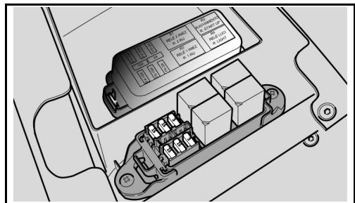
04_22
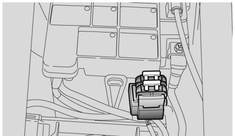
04_23
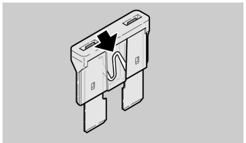
04_24
Fusibles (04_22, 04_23, 04_24, 04_25, 04_26)
ATENCLON
NO REPARAR FUSIBLES DEFECTUOSOS.
NUNCA UTILIZAR FUSIBLES DIFERENTES A LOS ESPECIFICADOS.
PODRÍA CAUSAR DANOS AL SISTEMA ELECTRICO E INCLUSO UN INCENDIO EN CASO DE CORTOCIRCUito.
NOTA
CUANDO UN FUSIBLE SE DANA FRECUENTEMENTE, ES PROBABLE QUE EXISTA UN CORTOCIRCUito O UNA SOBRECARGA. EN ESTE CASO CONSULTAR UN Concesionario Oficial Moto Guzzi.
Si se detecta que un componente électrique no funciona o funciona en forma anormal, o no se produce el arranque del motor, esnecessary controlar los fusibles.
Controlar primero los fusibles secundarios y bajo los fusibles principales.
Para el control:
- Colocar en 'OFF' el conmutador de arranque, para evaporar un cortocircui
Fuses (04_22, 04_23, 04_24, 04_25, 04_26)
CAUTION
DO NOT REPAIR FAULTY FUSES.
NEVER USE FUSES OTHER THAN THE ONES SPECIFIED.
A SHORT CIRCUIT MAY DAMAGE THE ELECTRICAL SYSTEM OR EVEN CAUSE A FIRE.
NOTE
IF A FUSE BLOWS OUT FREQUENTLY, THAT MAY BE DUE TO A SHORT CIRCUIT OR OVERLOAD. IF THIS OCCURS, CONTACT AN Official Guzzi Dealer.
Checking the fuses is necessary whenever an electrical component fails to operate or is malfunctioning or when the engine does not start.
First check the secondary fuses and then the main fuses.
To check:
- Set the ignition switch to 'OFF' to avoid an accidental short circuit.
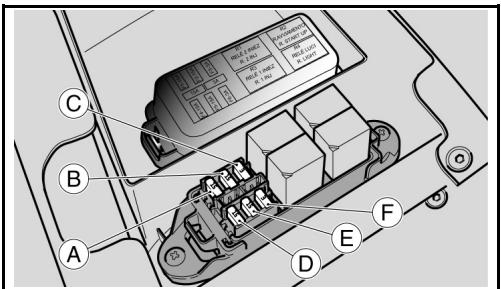
04_25
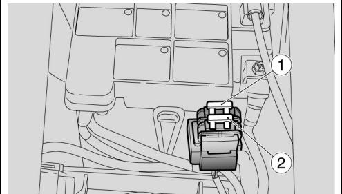
04_26
to accidental.
Extraer el asiento del piloto.
- Abrir la tapa de la caja de los fusibles secundarios.
Extraer un fusible por vez y controlar si el filamento está interrupido.
- Antes de sustituir el fusibleUGCAR, si es possible, la causa que ha pro-. vocabido el inconveniente.
- Sustuir el fusible, si esta dañado, con除外 del"Myismo amperaje.
NOTA
SI SE UTILIZA UN FUSIBLE DE REServa, REPONER UNO IGUAL EN EL ALOJAMIENTO CORRESPONDIENTE.
-forky: A new, small, and simple, but often not always perfect, form of a fusion.
-Partially: A fusion with some defects, such as the lack of symmetry, or the lack of symmetry in the two dimensions.
-Partially-fusible: A fusion with defects, such as the lack of symmetry, or the lack of symmetry in the two dimensions.
NOTA
EXTRAER LOS FUSIBLES DE 30A IMPLICA PONER A CERO LAS FUNCIONES: RELOJ DIGITAL, INFORMACIONES DE VIAJE Y MEDICIONES CRONOMETRICAS.
- Remove the rider saddle.
-
Open the cover of the secondary fuses box.
-
Extract a fuse at a time and check if the linked is divided.
Before replacing the fuse, identify the cause of the failure if possible. - Replace the damaged fuse with one of equal current rating.
NOTE
IF A SPARE FUSE IS USED, SUPPLY ANOTHER OF THE SAME TYPE IN THE CORRESPONDING FITTING.
- To check main fuses carry out the same operations described above for auxiliary fuses.
NOTE
REMOVING THE 30 A FUSES RESETS THESE FUNCTIONS: DIGITAL CLOCK, TRIP INFORMATION AND CHRONOMETRICAL TIMES.
FUSIBLES SECUNDARIOS
SECONDARY FUSES
A - Stop, claxon, bobina, reli luces (15 A).
B - Luces de posicón, luz de matricula, passing, relé arranque (15 A).
C - Positivo bajo tension, GPS "Tom - Tom" (3A)
D - Bomba gasolina, bobinas, inyectores (15 A).
E - Quemador lambda, bobina rele de inyeccion secundario, bobina rele de arranque, alimentacion sensor de velocidad, alimentacion centralita ECU (15 A).
F - Positivo permanente, alimentacion centralita ECU (3 A).
NOTA
DOS FUSIBLES SON DE RESERVA.
FUSIBLES PRINCIPALES
1 - De bateria a regulator de tension (30 A).
2 - De batería a llave y fusibles secundarios C - D (30 A).
NOTA
UN FUSIBLE ES DE RESERVA.
A - Stop, horn, coil, light relay (15 A).
B - Tail lights, license plate light, passing, ignition relay (15 A).
C - Positive live lead, "Tom - Tom" GPS (3A)
D - Fuel pump, coils, injectors (15 A).
D - Lambda burner, secondary injection relay coil, ignition relay coil, speed sensor power supply, engine kill, ECU power supply (15 A).
F- Permanent positive, ECU power supply (3A).
NOTE
THERE ARE TWO SPARE FUSES.
MAIN FUSES
1 - From battery to voltage regulator (30 A).
2 - From battery to key and secondary fuses C - D (30 A).
NOTE
THERE IS ONE SPARE FUSE
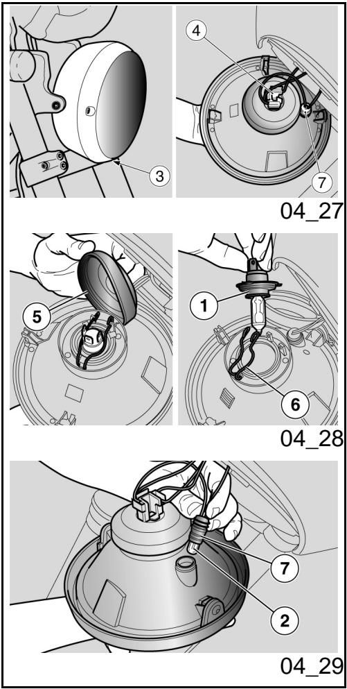
Bombillas (04_27, 04_28, 04_29)
ATENCIón

ANTES DE SUSTITUIR UNA BOMBILLA, COLOCAR EL INTERRUPTOR DE ARRANQUE EN LA POSICION «OFF» Y ESPERAR ALGUNOS MINUTOS PARA PERMITIR EL ENFRIAMIENTO DE LA MISMA.
SUSTITUIR LA BOMBILLA USANDO GUANTES LIMPIOS O USANDO UN PANO LIMPIO Y SECO.
NO DEJAR HUELLAS EN LA BOMBILLA PORQUE PODRIA CAUSAR SU SOBRECALENTAMENTO Y LUEGO SU ROTURA. SI SE TOCA LA BOMBILLA CON LAS MANOS DESNUDAS, LIMPIAR CON ALCOHOL LAS EVENTUALES HUELLAS PARA EVITAR QUE SE DANE.
NO FORZAR LOS CABLES ELECTRICOS.
DISPOSICION BOMBILLAS
En el faro delantero está alojadas:
- una bombilla (1) de luz de cruce / de carretera (superior);
- una bombilla (2) de luz de posicion (inferior);
Lamps (04_27, 04_28, 04_29)
CAUTION

BEFORE REPLACING A BULB, TURN THE IGNITION SWITCH TO «KEY OFF» AND WAIT A FEW MINUTES FOR THE BULB TO COOL OFF.
Wear CLEAN GLOVES OR USE A CLEAN DRY CLOTH TO REPLACE THE BULB.
DO NOT LEAVE PRINTS ON THE BULB AS THIS MAY CAUSE IT TO OVERHEAT OR EVEN BLOW OUT. IF YOU TOUCH THE BULB WITHOUT WEARING GLOVES, CLEAN OFF PRINTS WITH ALCOHOL TO AVOID DAMAGING THE BULB.
DO NOT FORCE ELECTRICAL CABLES.
BULB LAYOUT
In the front headlight there are:
-one high-beam / low-beam bulb (1) (upper);
-one tail light bulb (2) (lower);
FRONT HEADLAMP BULB REPLACEMENT
SUSTITUCION BOMBILLAS FARO DELANTERO
- Colocar el vehiculo sobre el caballete.
- Retirar la parábola completeness del cuerpo del projector desenroscando el tornillo (3).
Rest the vehicle on its stand.
- Remove the complete parabole from the headlight body by undoing the screw (3).
BOMBILLA DE LUX DE CRUCE / DE CARREtera
- Sujetar el conector eletrico de la bombilla (4), tirar de el y desconectarlo de la bombilla.
- Desplazar con las manos la cubierta (5).
- Desenganchar los dos extremos del muelle de retencion (6) colocado en el portalampara.
Extraer la bombilla (1) de su alojamento.
LOW-BEAM / HIGH-BEAM LIGHT BULB
Pull out the electrical connection to the bulb (4), and disconnect it from the bulb.
- Move hood (5) manually.
- Release the two ends of the retaining spring (6) located on the bulb holder.
Pull the bulb (1) out of its seat.
NOTA
INTRODUCIR LA BOMBILLA EN EL PORTALÁMPARAS HACIENDO COINCIDIR LOS ALOJAMIENTOS DE POSICIONAMIENTO.
Instalar correctamente una bombilla del mesmo Modelo.
NOTE
INSERT THE BULB INTO THE BULB HOLDER, MAKING SURE THE REFERENCE FITTINGS MATCH.
Install a bulb of the same type adequately.
BOMBILLA LUX DE POSICION
- Sujetar el portalámparas de luz de posición (7), tirar de el y extraerlo de su alojimiento.
- Sacar la bombilla (2) y sustituirla por una del mesmo Modelo.
- Controlar que se haya colocado correctamente la bombilla en el portalámparas.
TAIL LIGHT BULB
Pull out the tail light bulb holder (7) from its seat.
- Remove the bulb (2) and replace it with another of the same type.
- Check the proper insertion of the bulb in the bulb holder.
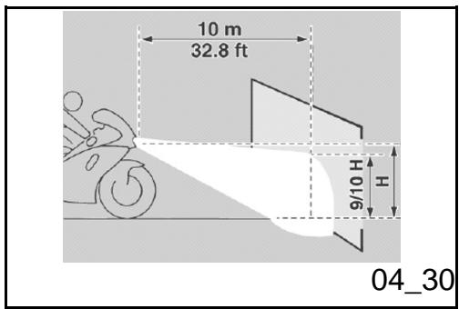
Regulación projector (04_30, 04_31)
NOTA
EN FUNCION DE LO PREVISTO POR LA LEGISLACION EN VIGENCIA EN EL PAís DONDE SE UTILICE EL VEHÍCULO, PARA EL CONTROL DE LA ORIENTACION DEL HAZ LUMINOSO SE DEBEN ADOPTAR PROCEDIMENTOS ESPECÍNICOS.
Headlight adjustment (04_30, 04_31)
NOTE
IN COMPLIANCE WITH LOCAL LEGAL REQUIREMENTS, SPECIFIC PROCEDURES MUST BE FOLLOWED WHEN CHECKING LIGHT BEAM ADJUSTMENT.
Para realizar un control rápido de la orientación correcta del haz luminoso delantero:
- Colocar el vehiculo a 10 m (32.8 ft) de distancia de una pared vertical, asegurándose de que el piso sea plano.
For a quick check of the correct direction of the front light beam:
- Place the vehicle 10m (32.8 ft) from a vertical wall and make sure the ground is level.
- Turn on the low-beam light, sit on
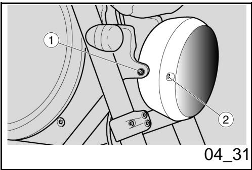
- Encender la luz de cruce, sentarse en el vehiculo y controlar que el haz luminoso proyectado en la pared quede inmediamente bajo de la recta horizontal del projector (aproximamente 9/10 de la alta total).
the scooter and check that the light beam projected to the wall is a little below the headlight horizontal straight line (about 9/10 of the total height).
Para la regulación vertical del haz luminoso:
- Colocar el vehiculo en posicion vertical.
- Aflojar levamente los tornillos (1) de fijación del projector y colocar manualmente el haz luminoso en la posición deseada.
- Efectuada la regulacion,pletar los tornillos (1).
In order to carry out vertical adjustment of the light beam:
- Stand the scooter in a vertical position.
- Slightly loosen the headlight fixing screws (1), and move the light beam manually to the desired position.
- Once the adjustment is finished tighten the screws (1).
Al finalizar la regulación:
NOTA
CONTROLAR LA CORRECTA ORIENTACION HORIZONTAL DEL HAZ LUMINOSO.
After adjusting:
NOTE
CHECK THAT THE LIGHT BEAM HORIZONTAL DIRECTION IS CORRECT.
Para la regulación horizontal del haz luminoso:
- Colocar el vehiculo en posicion vertical.
In order to carry out horizontal adjustment of the light beam:
-
Stand the scooter in a vertical position.
-
Accionando el tornado (2) regular la orientación del haz luminoso.
Al finalizar la regulación:
ATENCLON
CONTROLAR LA CORRECTA ORIENTACION VERTICAL DEL HAZ LUMINOSO.
- Actuating on the screw (2) adjust the direction of the light beam.
After adjusting:
CAUTION
CHECK THAT THE LIGHT BEAM VERTICAL DIRECTION IS CORRECT.
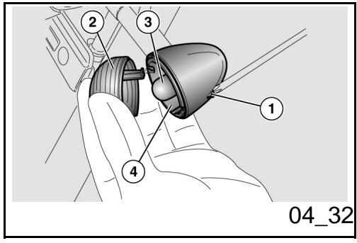
Indicadores de direccion delanteros (04_32)
Desenroscar y quitar el tornillo (1).
- Quitar la pantalla de proteccion (2) con是多么sciousao para no romper el diente de encastre.
- Empujar la bombilla (3) con moderation y girarla en sentido contrario a las agujas del reloj.
Extraer la bombilla (3) de su alojamento.
- Introducir una bombilla del mesmo modelo en el portalámparas, hacerlo coincidir las dos espigas guía con las guías respectivas del portalámparas.
Front direction indicators (04_32)
- Loosen and remove the screw (1).
- Remove the protective screen (2), proceeding with caution in order not to break off the retainer tabs.
- Press the bulb (3) in slightly and turn in anticlockwise direction.
- Remove the bulb (3) from its seat.
Install a bulb of the same type in the bulb holder, aligning the two guide pins with the corresponding guides on the bulb holder.
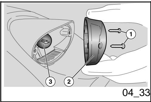
Grupo optico trasero (04_33)
- Colocar el vehiculo sobre el caballete.
Desenroscar y extraer los dos tornillos (1). - Sacar la pantalla de proteccion (2) procediendo conscious.
- Presionar con moderation la bombilla (3) y girarla en sentido antihora-rio.
Extraer la bombilla (3) de su alojamento. - Introducir una bombilla del mesmo tipo en el portalámparas, haciendo coincidir las dos espigas de guía con las guías correspondientes en el portalámparas.
- Apretar con cuidado y moderamente los dos tornillos (1) para evitar que se dañe la pantalla de protección (2).
Rear optical unit (04_33)
Rest the vehicle on its stand.
- Undo and remove the two screws (1).
- Remove the protective glass (2) with caution.
- Press the bulb (3) slightly and turn it anticlockwise.
Pull the bulb (3) out of its fitting.
- Insert a bulb of equal rating in the bulb holder making the two guiding pins coincide with their guides on the bulb holder.
- Tighten the two screws (1) carefully and moderately so as to avoid damaging the protective glass (2).
Indicadores de direccion traseros
Para la sustitución de las bombillas de los intermitentes traseros proceder de la mesma forma que con los intermitentes delanteros.
Rear turn indicators
To replace the rear turn indicator bulbs follow the same procedure described for front turn indicators.
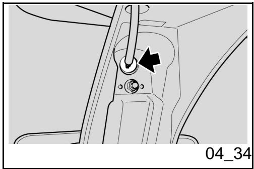
Luz plac (04_34)

ESPERAR A QUE EL MOTOR SE ENFRIE COMPLETAMENTE.
ATENCIón

PARA EXTRAER EL PORTALÁMPARAS NO JALAR LOS CABLES ÉLECTRICOS.
Number plate light (04_34)

ALLOW ENGINE TO COOL OFF.
CAUTION

DO NOT PULL THE ELECTRICAL CABLES WHEN TAKING OUT THE BULB HOLDER.
-
Operando desde el lado interior del portamatricula, sujetar el portalámparas, tirar del本身就是 y sacarlo de su alojamento.
Extraer y sustituir la bombilla por una del mesmo tipo. -
Working from the inner side of the licence plate holder, hold the bulb holder, pull and disconnect it from its fitting.
- Slide off and replace the bulb with another one of the same type.
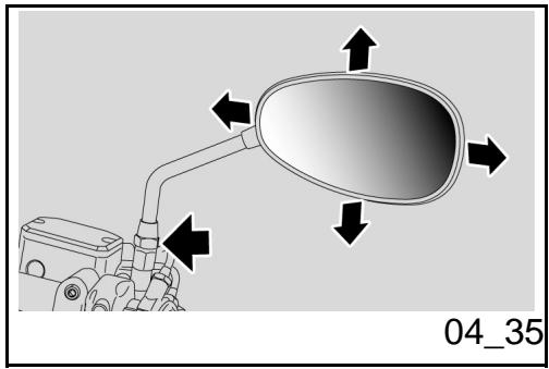
Espejos retrovisores
(04_35, 04_36)

NUNCA CONDUZCA CON LOS ESPEJOS RETROVISORES GIRADOS INCORRECTAMENTE.
ASEGURARSE SIEMPRE, ANTES DE PARTIR, DE QUE SE ENCUESTREN EN
Rear-view mirrors (04_35, 04_36)

DO NOT RIDE WITH REAR-VIEW MIRRORS INCORRECTLY SET.
BEFORE RIDING OFF, ALWAYS MAKE SURE THEY ARE CORRECTLY ADJUSTED TO RIDE.
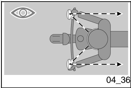
POSiCION DE TRABAJO Y CORRECTAMENTE REGULADOS.
Extraer los espejos retrovisores:
- Posicionar el vehiculo en el caballete.
- Aflojar la tuerca de bloqueo.

AL VOLVER A MONTAR, ASEGURARSE, ANTES DE APRETAR LA TUERCA DE BLOQUEO, QUE LA BARRA QUE SOSTIENE EL ESPEJO RETROVISOR ESTE ORIENTADA DE TAL MODE QUE RESULTE ALINEADA CON EL MANILLAR.
- SACar hacia arriba y extraer el groupo espejo retrovisorcomplete.
Eventually repetir la operation para extraer el other espejo retrovisor.
Regulación espejos retrovisores:
- Subir al vehiculo en posicio de conducccion.
Girar el espejo regulando correctamente la inclinación.
Repetir el mesmo procedimiento para regular elOTHERESpejo retrovisor.
- Controlar que no presenten deposi
Rear-view mirrors removal:
- Place the vehicle on its stand.
- Loosen the locking nut.

UPON REFITTING AND BEFORE TIGHTENING THE LOCKING NUT, MAKE SURE THAT THE REAR VIEW MIRROR SUPPORT STEM IS ALIGNED WITH THE HANDLEBAR.
- Slide up and remove the complete rear-view mirror unit.
Repeat the procedure to remove the other rear-view mirror, if necessary.
Rear-view mirrors adjustment:
Get on the vehicle in riding position.
- Turn mirror and adjust the correct angle.
Repeat the procedure to adjust the other mirror.
Make sure there is no dirt or mud.
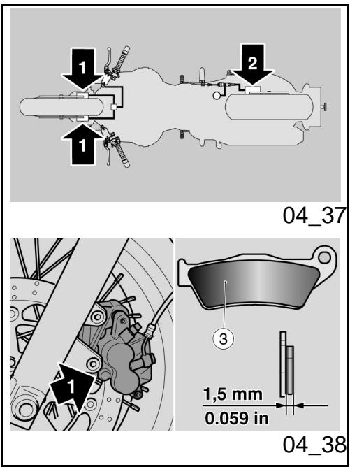
Freno de disco delantero y
trasero (04_37, 04_38,
04_39)
ATENCLON

UN DISCO SUCIO ENSUCIA LAS PASTILLAS, CON LA CONSIGUIENTE REDUCIOn DE LA EFICACIA DE FRENADO.
LAS PASTILLAS SUCIAS SE DEBEN SUSTITUIR, MIENTRAS QUE EL DISCO SUCIOSE DEBE LIMPIAR CON UN PRODUCTO DESENGRAANTE DE ALTA CALIDAD.
ATENCLON
PARA EXTRAER LA RUEDA TRASERA DIRIGIRSE A UN Concessionario Oficial Moto Guzzi.
Front and rear disc brake (04_37, 04_38, 04_39)
CAUTION

A DIRTY DISC SMEARS THE PADS RESULTING IN POOR BRAKING.
REPLACE DIRTY PADS AND CLEAN AGAIN THE DIRTY DISC USING A TOP QUALITY DEGREASING PRODUCT.
CAUTION
TAKE YOUR VEHICLE TO AN Official Moto Guzzi Dealer TO HAVE THE REAR WHEEL REMOVED.
ATENCIón

CONTROLLER EL DESGASTE DE LAS PASTILLAS DE FRENOS SOBRETodo ANTES DE CADA VIAJE.
CAUTION

CHECK BRAKE PADS FOR WEAR MAINLY BEFORE EACH RIDE.
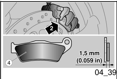
Para realizar el control rápido del desgaste de las pastillas:
- Colocar el vehiculo sobre el caballete.
-
Efectuar un control visual entre el disco y las pastillas trabajo:
-
desde arriba y desde abras,para la pinza del freno delantero (1);
- sobre elazo opuesto de la moto, a工程技术 de la llanta, para la pinza del freno trasero (2).
ATENCLON
EL CONSUMO, SUPERADO EL LIMITE DEL MATERIAL DE FRIICION, CAUSA RIA EL CONTACTO DEL SOPORTE METÁLICO DE LA PASTILLA CON EL DISCO, CON EL CONSIGUIENTE RUIDO METÁLICO Y ESCAPE DE CHISPAS DE LA PASTILLA; LA EFICACIA DE FRENADO, LA SEGURIDAD Y EL BUEN ESTADO DEL DISCO QUEDARIAN DE Este MODO COMPROMETIDOS.
Si el espesor del material de friccion (incluso de una sola pastilla delantera (3) o trasera (4)) se encontrar reducido hasta aproximamente 1,5 mm. (0,059 in) (o si uno solo de losindicadores de desgaste no es visible) hacer sustituir todas las pastillas de las pin
To carry out a quick pad wear check:
Rest the vehicle on its stand.
- Carry out a visual inspection of brake disc and pads as follows:
- look from above at the rear to check the front brake calliper (1);
- on the opposite side of the vehicle and through the rim, check the rear brake calliper (2).
CAUTION
EXCESSIVE WEAR OF FRICTION MATERIAL MAKES THE PAD METAL SUPPORT GET INTO CONTACT WITH THE DISC, WHICH RESULTS IN A METALLIC NOISE AND SPARKS IN THE CALLIPER; THIS COMPROMISES BRAKING EFFICIENCY AND SAFE RIDING AS WELL AS DAMAGES THE DISC.
If the friction material thickness (even of one front (3) or rear (4) pad) is reduced to a value of about 1.5mm (0.059 in) (or even if one of the wear indicators is not very visible), contact an Official Moto Guzzi Dealer to replace all the calliper pads.
Inactividad del vehiculo (04_40)
En caso de una larga inactividad del vehiculo:
Extraer la bateria.
Lavarysecarelvehiculo.
- Pasar cera en las superficies pintadas.
Inflar los neumáticos.
- Situar el vehiculo en un local no calefactionado, libre de humedad, protegado de los rayos solares en donde las variaciones de temperatas sean minimas.
- Colocar y atar una Bolsa de plástico en el extremo del escape del silenciador para evitar que ingrese humedad.
ATENCIón
SE ACONSEJA COLOCAR EL VEHICULO SOBRE SOPORTES ESTABLES QUE MANTENGAN AMBOS NEUMÁTICOS LEVANTADOS DEL SUELO.
Cubrir el vehiculo evitando usar materiales plácicos impermeables.
Periods of inactivity (04_40)
In case of prolonged vehicle inactivity:
- Remove the battery.
- Wash and dry the vehicle
- Polish painted surfaces with wax.
Inflate the tyres. - Store the scooter in a cool, dry place, not exposed to sun rays and with minimum temperature variations.
- Wrap and tie a plastic bag around the exhaust pipe openings to keep moisture out.
CAUTION
PLACE THE VEHICLE ON SUITABLE SUPPORTS TO KEEP THE TYRES OFF THE GROUND.
Cover the vehicle but do not use plastic or waterproof materials.
ATENCLON
PARA EVITAR QUE SE DETERIORE LA BATERIA, PROCEDER COMO SE HA INDICADO PARA LOS PERIODOS DE INACTIVIDAD PROLONGADA.
CAUTION
TO AVOID BATTERY DETERIORATION, FOLLOW THE PROCEDURE DESCRIBED FOR PROLONGED INACTIVITY.
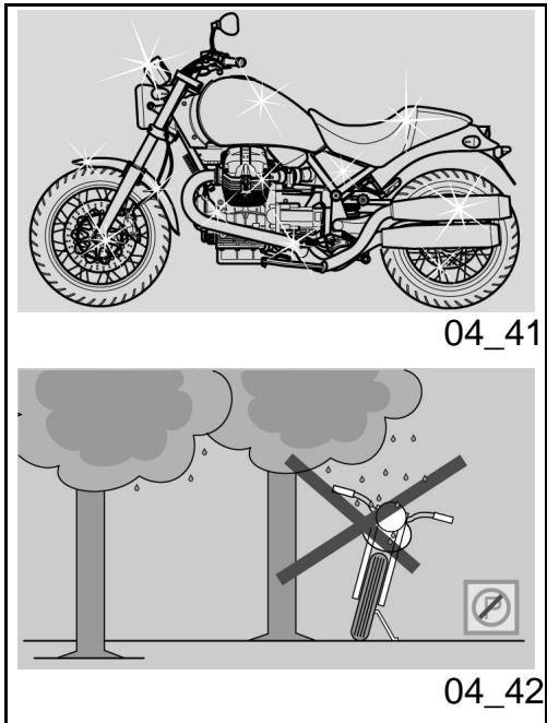
Limpieza del vehiculo (04_41, 04_42, 04_43)
Limpiar frecuentemente el vehiculo si se utilizes en zonas o en condiiones de:
- Contaminación atmosférica (ciudad y zonas industriales).
Salinidad y humedad de la atmosa- rara (zonas marinas, clima calido y humedo). - Partículares conditiones ambientales/estaciones (uso de sal, produits químicos anticongelantes en carreteras durante el periodo inerval).
- Se debe dedicular especial atencion para evacar que en la carroceria queden depuestos, residuos de polvos industriales y contaminantes, manchas de alquitrán, insectos muertos, excrementos de pájaros, etc.
- Evitar aparcar el vehiculo bajo de los árboles. En algunos estaciones, de los árboles caen residuos, resinas, frutos y hojas que contienen sustancias químicas dañinas para la
Cleaning the vehicle (04_41, 04_42, 04_43)
Clean the scooter frequently if exposed to adverse conditions, such as:
Air pollution (cities and industrial areas).
- Atmospheric salinity and humidity (seashore areas, hot and wet weather).
- Special ambient/seasonal conditions (use of salt, anti-icing chemical products on the roads in winter).
- Make sure to clean off any industrial residue and pollutants, tarmac, dead insects, bird droppings etc. from the vehicle fairings.
- Avoid parking the vehicle under trees. Resins, fruits or leaves falling from trees may contain aggressive chemical substances that may damage the paintwork.
CAUTION

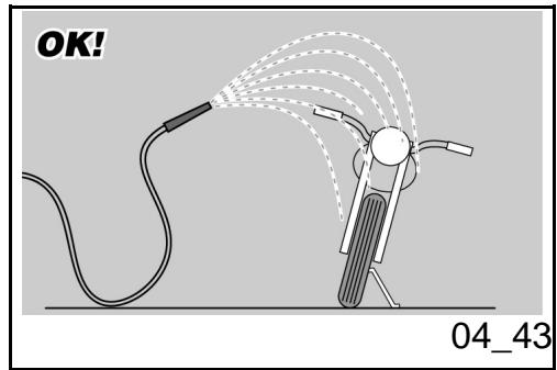
pintura.
ATENCIón

ANTES DE LAVAR EL VEHICULO, TAPAR LAS TOMAS DE AIRE DE ASPIRACION DEL MOTOR Y LOS ESCAPES DEL SI-LENCIADOR.
ATENCLON


DESPUÉS DE LAVAR EL VEHÍCULO, LA EFICIENCY DEL FRENADO PODRÍA VERSE MOMENTANENTE COMPROMETIDA A CAUSA DE LA PRESENCIA DE AGUA EN LAS SUPERFICIES DE FRICION DE LA INSTALACION DE FRENOS. ES NECESARIO PREVER DISTANCIAS MAYORES DE FRENADO PARA EVITAR ACCIDENTES. ACCIONAR REPETIDAMENTE LOS FRENOS PARA RESTABLECER LAS CONDICIONES NORMALES. EFFECTUAR LOS CONTROLES PRELIMINARES.
Para eliminar la suciedad y el fango depositos en las superficies pintadas, es necesario usar unchorro de agua a bajo presión,
BEFORE WASHING THE VEHICLE, COVER THE ENGINE AIR INTAKES AND THE EXHAUST PIPES.
CAUTION


AFTER CLEANING YOUR VEHICLE, BRAKING EFFICIENCY MAY BE TEMPORARILY AFFECTED DUE TO THE PRESENCE OF WATER ON THE FRICTION SURFACES OF THE BRAKING CIRCUIT. CALCULATE A LONGER BRAKING DISTANCE IN ORDER TO AVOID ACCIDENTS. BRAKE REPEATEDLY TO RESTORE NORMAL OPERATION. CARRY OUT THE PRE-RIDE CHECKS.
To clean off dirt and mud deposited from painted surfaces, soften caked dirt with a low-pressure water jet. Sponge off using a
mojar cuidadosamente las partes sucias, eliminar el fango y la suciedad con una esponja suave para carrocería, embebida en abundante agua y champú (2 ÷ 4 partes de champú en agua). Luego enjuagar con abundante agua y secar con una gamuza. Para limpar las partes exteriorores del motor, utiliser detergentes desengrasantes, pinceles y traps. Las partes de aluminio anodizzato o pintado como horquillas, llantas, chasis, estribos, etc. se deben lavar con jabón neutro y agua. El uso de detergentes demasiado agresivos pueda arrunar el tratimiento de la superficie de这些东西 componentes.

PARA LA LIMPIEZA DE LOS FAROS, UTILizar UNA ESPONJA EMBEBIDA EN DETERGENTE NEUTRO Y AGUA, FROTANDO CON DELICADEZA LAS SUPERFICIES Y ENJUAGANDO FRECUNITENTE CON ABUNDANTE AGUA. SE RECUERDA QUE EL LULARDO CON CERA SILICONADA SE DEBE REALizar DESPUES DE UN CUIDADOSO LAVADO DEL VEHICULO. NO LULARR CON PASTAS ABRASIVAS LA PINTURA OPACA. NO LAVAR AL SOL, ESPECIALMENTE EN VERANO CON LA CAROCERIA TODAVIA CALIENTE, PORQUE SI EL CHAMPU SE SECA ANTES DE ENJUAGARLO PODRIA CAUSAR DANOSA LA PINTURA.
ATENCIón
car body sponge soaked in a car body shampoo and water solution (2 ÷ 4% parts of shampoo in water). Then rinse with plenty of water, and dry with a chamois leather. To clean the engine outer parts, use degreasing detergent, brushes and old cloths. Anodised or painted aluminium parts such as forks, rims, frame, footrests etc. should be washed using water and mild soap. Using aggressive detergents may damage the surface treatment of these components.

TO CLEAN THE HEADLIGHTS USE A SPONGE SOAKED IN WATER AND MILD DETERGENT, RUBBING THE SURFACE GENTLY AND RINSING FREQUENLY WITH PLENTY OF WATER. REMEMBER TO CLEAN THE VEHICLE CAREFULLY BEFORE ANY POLISHING WITH SILICON WAX. DO NOT POLISH MATT-PAINTED SURFACES WITH POLISHING PASTE. THE VEHICLE SHOULD NEVER BE WASHED IN DIRECT SUNLIGHT, ESPECIALLY DURING SUMMER, OR WITH THE BODYWORK STILL HOT AS THE CAR SHAMPOO CAN DAMAGE THE PAINTWORK IF IT DRIES BEFORE BEING RINSED OFF.
CAUTION

DO NOT USE WATER (OR LIQUIDS) AT

NO UTILIZAR AGUA (O LIQUIDOS) A UNA TEMPERATUREA SUPERIOR A LOS 40^ (104^) PARA LA LIMpieZA DE LOS COMPONENTES DE PLASTICO DEL VEHICULO. NO DIRIGIR CHORROS DE AGUA O DE AIRE A ALTA PRESION O CHORROS DE VAPOR EN LAS SIGUIENTES PARTES: CUBOS DE LAS RUELAS, MANDOS SITUADOS EN EL LADO DERECHO E IZQUIERDO DEL MANILLAR, COJINETES, BOMBAS DE FRENOS, INSTRUMENTOSE INDICADORES, ESCAPE DEL SILENCIADOR, INTERRUPTOR DE ARRANQUE / BLOQUEO DEL MANILLAR. NO UTILIZAR ALCOHOL NI SOLVENTES PARA LA LIMpieZA DE LAS PARTES DE GOMA O PLASTICO, NI PARA EL ASIENTO. UTILizar, EN CAMBIO, AGUA Y JABON NEUTRO.
ATENCIón
PARA LIMPIAR EL ASIENTO NO UTILIZAR SOLVENTES O DERIVADOS DE PETROLEO (ACETONA, TRICLOROETILENO, TREMENTINA, BENCINA, DILUYENTES) SE PUEDEN UTILizar DETERGENTES QUE CONTENGAN TENSIOACTIVOS NO SUPERIORES AL 5% (JABON NEUTRO, DETERGENTE DESENGRASANTE O ALCOHOL).
SECAR CON CUIDADO EL ASIENTO AL FINALIZAR LA LIMpieZA.
TEMPERATURES OVER 40^ (104^) WHEN CLEANING PLASTIC PARTS OF THE SCOOTER. DO NOT AIM HIGH PRESSURE AIR/WATER JETS OR STEAM JETS DIRECTLY TO THE FOLLOWING PARTS: WHEEL HUBS, CONTROLS ON THE RIGHT AND LEFT SIDE OF THE HANDLEBAR, BEARINGS, BRAKE PUMPS, INSTRUMENTS AND GAUGES, EXHAUST SILENCER, IGNITION SWITCH/STEERING LOCK. DO NOT USE ALCOHOL OR SOLVENTS TO CLEAN ANY RUBBER OR PLASTIC SADDLE COMPONENTS: USE WATER AND MILD SOAP INSTEAD.
CAUTION
DO NOT USE SOLVENTS OR PETROL BYPRODUCTS (ACETONE, TRICHLOROETHYLENE, TURPentine, PETROL, THINNERS) TO CLEAN THE SADDLE. USE INSTEAD DETERGENTS WITH SURFACE ACTIVE AGENTS NOT EXCEEDING 5% (NEUTRAL SOAP, DEGREASING DETERGENTS OR ALCOHOL).
DRY THE SADDLE WELL AFTER CLEANING.
CAUTION

DO NOT APPLY ANY PROTECTIVE WAX ON THE SADDLE OR IT MAY BECOME SLIPPERY.
ATENCLON

NO APLICAR EN EL ASIENTO CERA DE PROTECCION, PARA EVITAR RESBALAMIENTOS.
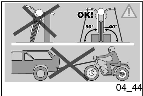
Transporte (04_44)
Antes de transporte el vehiculo es necesario vinciar@cuidadosamente el deposito de combustible,controlando que quede complemente seco.
Durante el desplazimiento el vehiculo debe mantener una posicion vertical, estar bien susjetado y tener acoplada la prima marcha, para evitar eventuales perdidas de combustible y de aceite.
EN CASO DE AVERIA NO REMOLCAR EL VEHICULO, SINO SOLICITAR LA INTERVENTION DE UN MEDIO DE AUXILIO.
Transport (04_44)
Before transporting the vehicle, empty the fuel tank well and make sure it is perfectly dry.
During transport the vehicle must be well anchored and upright, and first gear must be engaged to avoid fuel and oil leaks.
IN CASE OF FAILURE, DO NOT HAVE THE SCOOTER TOWED. ASK FOR ROAD ASSISTANCE SERVICE.
Bellagio


Cap. 05
Datas技术和
Chap. 05
Technical data
DIMENSIONES Y MASA
| Característica | Descripción/Valor |
| Longitud | 2253 mm (88.70 in) |
| Anchura (a las palancas del freno / embrague) | 820 mm (32.30 in) |
| Altura (a las bombas de freno/ embrague) | 1130 mm (44.50 in) |
| Altura asiento | 780 mm (30.71 in) |
| Altura minima desde el suelo | 150 mm (5.9 in) |
| Distancia entre ejes | 1560 mm (61.42 in) |
| Peso enorden de marcha | 237 kg (522 lb) |
WEIGHT AND DIMENSIONS
| Specification | Desc./Quantity |
| Length | 2253 mm (88.70 in) |
| Width (to the brake / clutch levers) | 820 mm (32.30 in) |
| Height (to the brake pumps / clutch) | 1130 mm (44.50 in) |
| Saddle height | 780 mm (30.71 in) |
| Minimum ground clearance | 150 mm (5.9 in) |
| Wheelbase | 1560 mm (61.42 in) |
| Kerb weight | 237 kg (522 lb) |
MOTOR
| Característica | Descripción/Valor |
| Tipo | bicilindrico transversal de V 90°, a cinco tiempos |
| Número de cilindros | 2 |
| Disposition cilindros | a V de 90° |
| Cilindrada | 935,6 cm³ (57.09 cu in) |
| Diámetro interior/carrera | 95 x 66 mm (3.74 x 2.66 cu in) |
ENGINE
| Specification | Desc./Quantity |
| Type | 90° transversal V-twin, four stroke |
| Cylinder quantity | 2 |
| Cylinder layout | 90° V |
| Cubic capacity | 935.6 cm³ (57.09 cu.in) |
| Bore / stroke | 95 x 66 mm (3.74 x 2.66 cu.in) |
| Compression ratio | 10:1 |
| Relación de compresión | 10:1 |
| Arranque | eléctrico |
| N° revoluciones del motor en ralentí | 1100 ± 100 rpm |
| Embrague | bidisco en seco |
| Sistema de lubricación | Sistema a presión regulado por valvulas y bomba trocoidal |
| Filtro de aire | con cartucho, en seco |
| Refrigeración | aire |
| Diagrama de distribución: | 2 valvulas de varillas y balancines |
| Valores validos con juego de control entre balancines y valvula | aspiración: 0,10 mm. (0.0039 in) escape: 0,15 mm. (0.0059 in) |
TRANSMISSION
| Característica | Descripción/Valor |
| Relación de transmisión | Principal de engranajes 24/35 |
| Cambio de velocidades | Mecánico de 6 relaciones con mando por pedal en el lado izquierdo del motor |
| Ignition | electronic |
| Engine revs at idle speed | 1100 ± 100 rpm |
| Clutch | dry, twin discs |
| Lubrication system | Pressure system regulated by valves and trochoidal pump |
| Air filter | dry cartridge air filter |
| Cooling | air |
| Timing system diagram: | 2 rod valves and rocking levers |
| Valid values with checking clearance between rocking levers and valve | inlet: 0.10 mm (0.0039 in) outlet: 0.15 mm (0.0059 in) |
TRANSMISSION
| Specification | Desc./Quantity |
| Gear ratio | Gear primary drive 24/35 |
| Gearbox | Mechanical, 6 speeds with foot lever on the left hand side of the engine |
| Relaciones cambio: | 1a marcha: 17/38 = 1: 2,2353 |
| 2a marcha: 20/34 = 1: 1,7 | |
| 3a marcha: 23/31 = 1: 1,3478 | |
| 4a marcha: 26/29 = 1: 1,1154 | |
| 5a marcha: 31/30 = 1: 0,9677 | |
| 6a marcha: 29/25 = 1: 0,8621 | |
| Transmisión final | a cardán |
| Relación | 12/44 = 1: 3.6667 |
| Gear ratios: | 1st gear: 17/38 = 1:2.2353 |
| 2nd gear: 20/34 = 1:1.7 | |
| 3rd gear: 23/31 = 1:1.3478 | |
| 4th gear: 26/29 = 1:1.1154 | |
| 5th gear: 31/30 = 1:0.9677 | |
| 6th gear: 29/25 = 1:0.8621 | |
| Final transmission | cardan shaft |
| Ratio | 12/44 = 1:3.6667 |
CAPACIDAD
| Characterística | Descripción/Valor |
| Cárter de aceite motor | 3000 cm³ (183 cu in) |
| Aceite del cambio de velocidades | 500 cm³ (30.5 cu in) |
| Aceite transmisión | 380 cm³ (23.2 cu in) |
| Combustible (incluidoresherva) | 19 +/- 0.5 l (5.02 +/- 0.13 US gal) |
| Reserva de combustible | 4 l (1.056 gal US) |
| Aceite horquilla telescónica regulable (para barra) | 0,485 l (0.128 US gal) |
| Plazas | 2 |
| Máxima cargavehúculo |
CAPACITY
| Specification | Desc./Quantity |
| Engine oil sump | 3000 cm³ (183 cu.in) |
| Gearbox oil | 500 cm³ (30.5 cu.in) |
| Transmission oil | 380 cm³ (23.2 cu.in) |
| Fuel (reserve included) | 19 +/- 0.5 l (5.02 +/- 0.13 US gal) |
| Fuel reserve | 4 l (1.056 US gal) |
| Adjustable telescopic fork oil (per fork leg) | 0.485 l (0.128 US gal) |
| Seats | 2 |
| Vehicle maximum load |
210 Kg (463 lb) (conductor + pasajero + equipaje)
210 kg (463 lb) (rider + passenger + luggage)
INSTALACION ELECTRICA
| Characterística | Descripción/Valor |
| Bujías - interiores | long life NGK PMR8B |
| Bujía exterior | NGK BPR6ES |
| Distancia entre electrodos | 0,6 - 0,7 mm (0.024 - 0.028 in) |
| Batería | 12 V - 18 Amperes/hora |
| Generador - alternador | Potencia de salute: 350 W a 5000 rpm. (12V - 25A) |
| Fusibles principales | 30 A |
| Fusibles secundarios | 3 - 15 A |
| Luz de posición | 12V - 5W |
| Luz de cruce/de carretera (halógena) | 12 V - 55 W / 60 W H4 |
| Intermitentes | 12V - 10W |
| Luz de posición trasera / stop | 12 V - 5 / 21 W |
| Illumínación instrumento | LED |
| Luz de matricula | 12V - 5W |
ELECTRICAL SYSTEM
| Specification | Desc./Quantity |
| Spark plugs - inner | long life, NGK PMR8B |
| Outer spark plug | NGK BPR6ES |
| Electrode gap | 0.6 - 0.7 mm (0.024 - 0.028 in) |
| Battery | 12 V - 18 Ampere/hour |
| Generator - alternator | Output power: 350 W at 5000 rpm (12V - 25A) |
| Main fuses | 30 A |
| Secondary fuses | 3 A - 15 A |
| Tail light | 12V - 5 W |
| Low-/ high-beam light (halogen) | 12 V - 55 W / 60 W H4 |
| Turn indicators | 12V - 10 W |
| Rear tail light / stop light | 12 V - 5 / 21 W |
| Instrument panel lighting | LED |
| License plate light | 12V - 5 W |
| Testigo intermitentes | LED |
| Testigo cambio en punto muerto | LED |
| Testigo caballete lateral bajo | LED |
| Testigo_reserved del combustible | LED |
| Testigo luz de carretera | LED |
| Testigo presión aceite | LED |
| Testigo de alarmas generales | LED |
ALIMENTACION
| Característica | Descripción/Valor |
| Alimentación | inyeción electrónica MULTIPOINT, secuencial puesta en fase MAGNETTI MARELLI IAW, Sistema ALFA-N. |
| Difusor | diámetro 40 mm. (1.57 in) |
| Combustible | Gasolina sufper sin plomo, octanaje minimum 95 (N.O.R.M.) y 85 (N.O.M.M.) |
| Turn indicator warning light | LED |
| Gear in neutral warning light | LED |
| Side stand down warning light | LED |
| Low fuel warning light | LED |
| High-beam warning light | LED |
| Oil pressure warning light | LED |
| General alarm warning light | LED |
FUEL SUPPLY
| Specification | Desc./Quantity |
| Fuel supply | MAGNETI MARELLI IAW MULTIPOINT electronic phased sequential fuel injection, ALFA-N System. |
| Diffuser | diameter: 40 mm (1.57 in) |
| Fuel | Premium unleaded petrol, minimum octane rating of 95 (NORM) and 85 (NOMM) |
CHASIS - SUSPENSIONES
| Characterística | Descripción/Valor |
| Chasis | Tubular de doble cuna de acero con alto límite de deformación elastica |
| Inclínación manguito de direccion | 28° |
| Avance | 92 mm (3.62 in) |
| Suspensión delantera | Horquilla telescónica hidráulica MARZOCCHI, diámetro 45 mm (1.77 in) con regulación separada del frenado hidrálico en extension y compresión. |
| Carrera de la rueda delantera | 140 mm (5.5 in) |
| Suspensión trasera - tipo | monobrazo con varillaje progresivo, monoamortiguidor regulable en extension y con puño ergonómico para la regulación de la precarga. |
| Carrera de la rueda trasera | 120 mm (4.7 in) |
FRENOS
| Característica | Descripción/Valor |
| Delantera | doble disco flotante de acero inox, |
CHASSIS - SUSPENSIONS
| Specification | Desc./Quantity |
| Chassis | Double cradle, high strength steel tube chassis |
| Headstock angle | 28° |
| Trail | 92 mm (3.62 in) |
| Front suspension | MARZOCCHI hydraulic telescopic fork, 45 mm (1.77 in) with separate adjustment for rebound and compression damping. |
| Front wheel travel | 140 mm (5.5 in) |
| Rear suspension - type | single arm suspension with progressive rising-rate leverage, single shock absorber with adjustable rebound and with ergonomic knob for preloading adjustment. |
| Rear wheel travel | 120 mm (4.7 in) |
BRAKES
| Specification | Desc./Quantity |
| Front: | stainless steel Ø 320 mm (12.6 in) |
| Ø 320 mm (12.6 in), pinzas flotantes Brembo, 2 pistones parallelos | |
| Trasera | doble disco flotante de acero inox, Ø 282 mm (11.1 in), pinza flotante Brembo, 2 pistones parallelos |
RUEdas Y NEUMATICOS
| Characterística | Descripción/Valor |
| Llantas de las ruedas | de radios |
| Llanta rueda delantera | 3,5" x 18" |
| Llanta rueda trasera | 5,50 x 17" |
| Neumáticos - Delantero medida | 120/70 - ZR 18" M/C 59 W |
| Neumáticos - Trasero medida | 180/55 - ZR 17" M/C 73 W |
| Neumáticos - modelos | METZELER Roadtec Z6 |
| Presión de inflado (delantero) | 230 Kpa (33.4 PSI) |
| Presión de inflado con pasajero (delantero) | 230 Kpa (33.4 PSI) |
| Presión de inflado (trasero) | 250 Kpa (36.3 PSI) |
| Presión de inflado con pasajero (trasero) | 270 Kpa (39.1 PSI) |
| twin floating disc, Brembo floating callipers with 2 parallel plungers | |
| Rear | stainless steel Ø 282 mm (11.1 in) fixed disc, Brembo floating calliper with 2 parallel pistons |
WHEELS AND TYRES
| Specification | Desc./Quantity |
| Wheel rims | with spokes |
| Front wheel rim | 3.5" x 18" |
| Rear wheel rim | 5.50 x 17 |
| Tyres - front size | 120/70 - ZR 18" M/C 59 W |
| Tyres - rear size | 180/55 - ZR 17" M/C 73 W |
| Tyres - type | METZELER Roadtec Z6 |
| Inflation pressure (front) | 230 kPa (33.4 PSI) |
| Inflation pressure with passenger (front) | 230 kPa (33.4 PSI) |
| Inflation pressure (rear) | 250 kPa (36.3 PSI) |
| Inflation pressure with passenger (rear) | 270 kPa (39.1 PSI) |
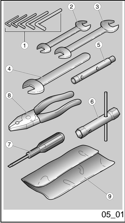
Herramentas enidotación (05_01)
La dotación de herramientos comprende:
-llaves macho hexagonales plegadas 3,4, 5,6,mm.(1);
- llave de horquilla doble 8 - 10 mm. (2);
- llave de horquilla doble 13 - 14 mm. (3);
- Ilave de horquilla 19 mm. (4);
- llave de tubo 8 - 10 mm.. (5);
- llave de tubo 17 - 21 mm. para bujía (6) y regulación precarga horquilla;
-destornillador de doble punta cruz / corte (7);
- pinza (8);
- un sobre de contentación (9);
Peso máximo permitido: 5 Kg en el compartmento portadocumentos más 5 Kg en el compartmento kit herramrientas.
Kit equipment (05_01)
The tools supplied are:
- 3-4-5-6-mm L-shaped Allen keys (1);
- 8 - 10-mm double open ended spanner (2);
- 13 - 14-mm double open ended spanner (3);
- 19-mm single open ended spanner (4);
- 8 - 10-mm box-spanner (5);
- 17 -21-mm box-spanner (6) for spark plugs and fork preloading adjustment;
- crosshead / plain slot screwdriver (7);
- pliers (8);
-one toolkit pouch (9);
Maximum weight allowed: 5kg in the glove compartment); +5kg in the toolkit compartment.
Bellagio


Cap. 06
Elmantimiento
programado
Chap. 06
Programmed
maintenance
Tabla manutencion programada
Un mantenimiento adecuado constituye un factor determinante para una mayor duración del vehúculo en conditiones óptimas de funciona y rendimiento.
A tal fin Moto Guzzi dispuso una series de controles y de intervenciones de mantenimiento a pagar, que se detallan en el cuadro sinóptico que se muestra en la頁a sigúiente. Es recomendable que eventualesymesas anomalías de functiónamente se informen inmediamente al Concesionario o Revendedor Autorizzato Moto Guzzi, sin esperar al suiviente control periodico para remediarlo.
Es indispensable能做到ar los controles periodicos en los intervals de kilometros y tiempos prescritos,apanas se alcanza el kilometraje previsto. Los controles periodicos demantimiento se deben efectuar punctualmente para la correctautilizacionde la garantia.Porequalquierotrainformacion relacionada conla modalidadde aplicacionde la Garantia y laexecution del"Mantenimientoprogramado",remitirse al"Manual de Garantia".
NOTA
EL TIEMPO PREVISTO PARA REALIZAR LAS OPERaciones DE MANTENIMIENT
Scheduled maintenance table
Adequate maintenance is fundamental to ensuring long-lasting, optimum operation and performance of your vehicle.
To this end, Moto Guzzi offers a set of checks and maintenance services (at the owner's expense) that are listed in the summary table shown on the following page. Any minor faults should be reported without delay to an Authorised Moto Guzzi Dealer or Sub-Dealer without waiting until the next scheduled service to solve it.
All scheduled maintenance services must be carried out at the specified times, even if the stated mileage has not yet been reached. Carrying out scheduled services on time is essential to ensure your warranty remains valid. For further information regarding Warranty procedures and "Scheduled Maintenance", please refer to the "Warranty Booklet".
NOTE
CARRY OUT MAINTENANCE OPERATIONS AT HALF THE INTERVALS SHOWN
EN CADA ARRANQUE
| Operación |
| Testigo presión aceite motor - controlar y limpiar, regular, lubricar o sustituir si es necesario |
ANTES DE CADA VIAJE Y CADA 2000 KM (1250 MILLAS)
| Operación |
| Desgaste pastillas de frenos - Controlar y limpiar, regular o sustituir si es necesario |
FINAL DEL RODAJE (1000 KM (625 MILLAS))
| Operación |
| Pernos de fijación bridas tubos de escape - Controlar y limpiar, regular, lubricar o sustituir si es NEEDario |
| Cables transmisión ymandos - controlar y limpiar, regular, lubricar o sustituir si es NEEDario |
AT EVERY START-UP
| Action |
| Engine oil pressure warning light - check and clean, adjust, grease or replace if necessary |
BEFORE EACH RIDE AND EVERY 2000 KM (1250 MI)
| Action |
| Brake pad wear - Check and clean, adjust or replace if necessary |
AFTER RUN-IN (1000 KM (625 MI))
| Action |
| Exhaust pipe flange bolts - Check and clean, adjust, grease or replace if necessary |
| Transmission cables and controls - Check and clean, adjust, grease or replace if necessary |
| Cojinetes de direccion y juego direccion - Controlar y limpiar, regular, lubricar o sustituir si es Neededo |
| Discos de frenos - Controlar y limpiar, regular o sustituir si esneededo |
| Filtro de aceite motor - sustitución |
| Horquilla - Controlar y limpiar, regular o sustituir si esneededo |
| Funcionamento general del vehiculo - Controlar y limpiar, regular, lubricar o sustituir si esneededo |
| Instalaciones de frenos - Controlar y limpiar, regular, lubricar o sustituir si esneededo |
| Instalaciones de luces - Controlar y limpiar, regular, lubricar o sustituirsi esneededo |
| Interruptores de seguridad - Controlar y limpiar, regular, lubricar o sustituir si esneededo |
| Aceite del cambio de velocidades - Sustituir |
| Aceite motor - Sustituir |
| Aceite de transmisión final - Sustituir |
| Neumáticos - Controlar y limpiar, regular o sustituir si esneededo |
| Presión de los neumáticos - Regular |
| Revoluciones motor en ralentí- Regular |
| Regulación juego de valvulas - Regular |
| Rueda - Controlar y limpiar, regular, lubricar o sustituir si esneededo |
| Apriete de pernos - Controlar y limpiar, regular, lubricar o sustituir si esneededo |
| Steering bearings and steering clearance - Check and clean, adjust, grease or replace if necessary. |
| Disc brakes - Check and clean, adjust or replace if necessary |
| Engine oil filter - Replace |
| Fork - Check and clean, adjust, grease or replace if necessary |
| General vehicle operation - Check and clean, adjust, grease or replace if necessary. |
| Braking systems - Check and clean, adjust, grease or replace if necessary |
| Light circuits - Check and clean, adjust, grease or replace if necessary |
| Safety switches - Check and clean, adjust, grease or replace if necessary |
| Transmission oil - change |
| Engine oil - Change |
| Final transmission oil - Change |
| Tyres - Check and clean, adjust or replace if necessary |
| Tyre pressure - Adjust |
| Engine revs at idle speed - Adjustment. |
| Valve clearance adjustment - Adjust |
| Wheels - Check and clean, adjust, grease or replace if necessary |
| Bolts, nuts and screws tightening - Check and clean, adjust, grease or replace if necessary |
| Battery terminals tightening - Check and clean, adjust, grease or replace if necessary |
| Ajuste bornes batería - Controlar y limpiar, regular, lubricar o sustituir si es besoino |
| Ajuste tornillos prisioneros culata - Regular |
| Ajuste tornillos culata - Regular |
| Sincronización cilindros - Controlar y limpiar, regular, lubricar o sustituir si es besoino |
| Suspensiones y ajuste - Controlar y limpiar, regular, lubricar o sustituir si es besoino |
| Desgaste pastillas de frenos - Controlar y limpiar, regular o sustituir si es besoino |
CADA 4 ANOS
Operación
Tubos combustible - Sustainir
Tubos frenos - Sustainir
CADA 5000 KM (3,125 MILLAS) - EN EL CASO DE CONDUCCION DEPORTIVA
Operación
| Bujías exteriorores - Sustituir |
| Filtro de aceite motor - sustitución |
| Vaciado del tubo de drenaje aceite de la caja del filtró - Limpiar |
| Head stud bolt tightening - Adjust |
| Head screws tightening - Adjust |
| Cylinder synchronisation - Check and clean, adjust, grease or replace if necessary |
| Suspensions and setting - Check and clean, adjust, grease or replace if necessary |
| Brake pad wear - Check and clean, adjust or replace if necessary |
EVERY 4 YEARS
| Action |
| Fuel pipes - Replace |
| Brake pipes - Replacement |
EVERY 5000 KM (3125 MI) - IF THE VEHICLE IS USED FOR RACING
| Action |
| Outer spark plugs - Replace |
| Engine oil filter - Replace |
| Purge fluid present in oil drainage pipe from the filter housing - Clean |
Desgaste embrague - Controlar y limpiar, regular o sustituir si es necessitiesario
CADA 10.000 Km (6,250 MILLAS) O 12 MESES
| Operación |
| Bujías exteriorores - Sustituir |
| Aceite del cambio de velocidades - Sustituir |
| Carburación al minimo (CO) - Controlar y limpiar, regular, lubricar o sustituir si es besoino |
| Cables transmisión ymandos - controlar y limpiar, regular, lubricar o sustituir si es besoino |
| Cojinetes de direccion y juego dirección - Controlar y limpiar, regular, lubricar o sustituir si es besoino |
| Cojinete de las ruedas = Controlar y limpiar, regular, lubricar o sustituir si es besoino |
| Discos de frenos - Controlar y limpiar, regular o sustituir si es besoino |
| Filtro de aire - Controlar y limpiar, regular, lubricar o sustituir si es besoino |
| Filtro de aceite motor - sustitución |
| Funcioncimiento general del vehicluo - Controlar y limpiar, regular, lubricar o sustituir si es besoino |
| Instalaciones de frenos - Controlar y limpiar, regular, lubricar o sustituir si es besoino |
Clutch wear - Check and clean, adjust, grease or replace if necessary
EVERY 10,000 KM (6250 MILES) OR 12 MONTHS
| Action |
| Outer spark plugs - Replace |
| Transmission oil - change |
| Idle mixture (CO) - Check and clean, adjust, grease or replace if necessary |
| Transmission cables and controls - Check and clean, adjust, grease or replace if necessary |
| Steering bearings and steering clearance - Check and clean, adjust, grease or replace if necessary. |
| Wheel bearings - Check and clean, adjust, grease or replace if necessary |
| Disc brakes - Check and clean, adjust or replace if necessary |
| Air filter - Check and clean, adjust, grease or replace if necessary |
| Engine oil filter - Replace |
| General vehicle operation - Check and clean, adjust, grease or replace if necessary. |
| Braking systems - Check and clean, adjust, grease or replace if necessary |
| Valve clearance adjustment - Adjust |
| Regulación juego de valvulas - Regular |
| Rueda - Controller y limpiar, regular, lubricar o sustituir si es besoino |
| Apriete de pernos - Controller y limpiar, regular, lubricar o sustituir si es besoino |
| Sincronización cilindros - Controller y limpiar, regular, lubricar o sustituir si es besoino |
| Vaciado del tubo de drenaje aceite de la caja del filtro - Limpiar |
| Aceite de transmisión final - Sustituir |
| Tubos del combustible - Controller y limpiar, regular, lubricar o sustituir si es besoino |
| Tubos de freno - Controller y limpiar, regular, lubricar o sustituir si es besoino |
| Desgaste embrague - Controller y limpiar, regular o sustituir si es besoino |
DESPUÉS DE LOS PRIMEROS 10.000 KM (6,250 MILLAS) Y DESPUÉS CADA 20.000 KM (12,500 MILLAS)
Operación
| Aceite horquilla - Sustituir |
| Retenes de aceite horquilla - Sustituir |
| Wheels - Check and clean, adjust, grease or replace if necessary |
| Bolts, nuts and screws tightening - Check and clean, adjust, grease or replace if necessary |
| Cylinder synchronisation - Check and clean, adjust, grease or replace if necessary |
| Purge fluid present in oil drainage pipe from the filter housing - Clean |
| Final transmission oil - Change |
| Fuel pipes - Check and clean, adjust, grease or replace if necessary |
| Brake pipes - Check and clean, adjust, grease or replace if necessary |
| Clutch wear - Check and clean, adjust, grease or replace if necessary |
AFTER THE FIRST 10,000 KM (6,250 MILES) AND THEN AFTER EVERY 20,000 KM (12,500 MILES)
| Action |
| Fork oil - Change |
| Fork oil seals - Replace |
CADA 20000 KM (12,500 MILLAS) O 24 MESES
| Operación |
| Bujías interiores - Sustituir |
| Correa alternador - Regular; cada 50.000 km sustituir |
| Filtro de aire - Sustituir |
| Horquilla - Controller y limpiar, regular o sustituir si es Neededo |
| Líquido de frenos - Sustitución |
| Aceite de transmisión final - Sustituir |
| Aceite del cambio de velocidades - Sustituir |
| Suspensiones y ajuste - Controller y limpiar, regular, lubricar o sustituir si es Neededo |
| Desgaste pastillas de frenos - Controller y limpiar, regular o sustituir si es Neededo |
EVERY 20,000 KM (12,500 MI) OR 24 MONTHS
| Action |
| Inner spark plugs - Replace |
| Alternator belt - Adjust; replace every 50,000 km |
| Air filter - Replace |
| Fork - Check and clean, adjust, grease or replace if necessary |
| Brake fluid - Change |
| Final transmission oil - Change |
| Transmission oil - change |
| Suspensions and setting - Check and clean, adjust, grease or replace if necessary |
| Brake pad wear - Check and clean, adjust or replace if necessary |
PRODUCTOS ACONSEJADOS
| Producto | Denominación | Característica |
| AGIP RACING 4T 10W-60 | Aceite motor | SAE 10W - 60. Como alternatively, se pueda utiliser aceites demarca o con prestaciones iguales o superfiores a las specifications CCMC G-4 A.P.I. SG. |
| AGIP ROTRA MP 80 W 90 | Aceite transmisión | - |
| AGIP ROTRA MP 85 W 90 | Aceite del cambio de velocidades | - |
| AGIP FORK 5W o FORK 20W | Aceite horquilla | SAE 5W / SAE 20W |
| AGIP GREASE SM2 | Grasa de litio con molibdeno para cojinetes yotiros punto de lubricación | NLGI 2 |
| Grasa neutra o vaselina. | Polos batería | |
| AGIP BRAKE 5.1 DOT 4 (el sistema defrenos es compatible también con DOT 5) | Líquido de frenos | Como alternatively, se pueda usar láquidos con prestaciones iguales o superiores a lasespecillas Fluido sintético SAE J1703, NHTSA 116 DOT 4, ISO 4925. |
RECOMMENDED PRODUCTS
| Product | Description | Specifications |
| AGIP RACING 4T 10W-60 | Engine oil | SAE 10W - 60. As an alternative for recommended oils, use top branded oils that meet or exceed the requirements of CCMC G-4 API SG specifications. |
| AGIP ROTRA MP 80 W 90 | Transmission oil | - |
| AGIP ROTRA MP/S 85 W 90 | Gearbox oil | - |
| AGIP FORK 5W or FORK 20W | Fork oil | SAE 5W / SAE 20W |
| AGIP GREASE SM2 | Lithium grease with molybdenum for bearings and other points needing lubrication | NLGI 2 |
| Neutral grease or petroleum jelly. | Battery poles | |
| AGIP BRAKE 5.1 DOT 4 (the braking system is also compatible with DOT 5) | Brake fluid | As an alternative for recommended fluids, use top branded fluids that meet or exceed the requirements of SAE J1703, NHTSA 116 DOT 4, ISO 4925 synthetic fluid specifications. |
Bellagio

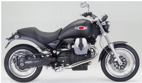
Cap. 07
Preparaciones
especiales
Chap. 07
Special fittings
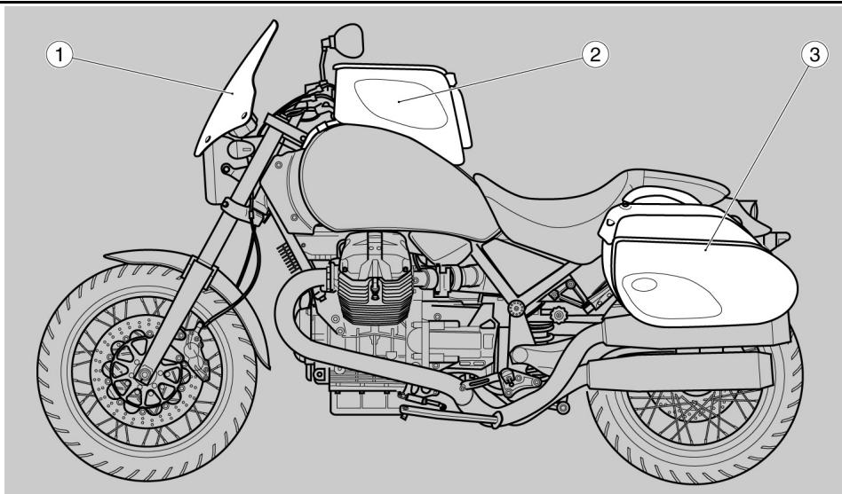
07_01
Indices accessories (07_01)
Están disponible los siguientes accesos:
- parabrisas
- maleta deposto grande / china
- kit maletas laterales semi-rigidas
-kit antirrobo
Accessories index (07_01)
The following accessories are available:
- windshield
- large / small tank bag
-
set of semi-rigid side panniers
-
antitheft kit
EL VALOR DE LA ASISTENCIA
Gracias a las continuasactualizaciones技术icas y alos programas de formacionespecifica sobre los productos Moto Guzzi,soleo mecanicos de la Red Oficial Moto Guzzi conocen profundamente este vehiculo y disponible del equipamento especial necessario para realizarcorrectamente de las intervenciones demantimiento y reparacion.
La confiabilitad del vehiculo también depende de sus condidiones mecancias. El control antes de conducir, el mantenimiento regular y el uso exclusivo de Repuestos Originales Moto Guzzi son factores esencias!
Para Obtener información sobre el Concesionario Oficial y/o Centro de Asistencia más cercano, consultar las Páginas Amarillas oocular directamente en el mapa de nuestro Sitio Web Oficial:
www.motoguzzi.it
Sólo solicitarando Repuestos Originales Moto Guzzi se tendrá un producto estudiado y probado durante la fase deprojecto del vehiculo. Los Repuestos Originales Moto Guzzi está sometidos sistématicamente a procedimientos de control de calidad, para garantizar su confiabilidad y duración en el tiempo.
Las descripción e ilustraciones que aparecen en la presente publicación no se consideran contractuales. Por lo tanto, Moto Guzzi se reserva el correcho de realizar, en cuales個 momento, las eventuales modificaciones a los organos, piezas o suministros de accesorios que considere convenrientes y que respondan a mejoras o a cuales exigencia de ccacter constructivo o commercial, respetando siempre las caracteristicas esencias del tipo descrito e ilustrado, y sin obligarse aactualizar inmediamente esta publicacion.
Algunas versiones presentadas en esta publicacion no estan disponible en algunos paises. La disponibilidad de cada version se debe comprobar en la red oficial de vente Moto Guzzi.
Copyright 2007- Moto Guzzi. Todos los derechos reservados. Prohibida la reproduccion total o parcial. Moto Guzzi - After sales service.
THE VALUE OF SERVICE
Only the mechanics of the official Moto Guzzi Service Network know this vehicle well, thanks to constant technical professional development and Moto Guzzi specific training programmes, and have the tools needed to carry out maintenance and repair operations correctly.
The reliability of the vehicle also depends on its mechanical conditions. Checking the vehicle before setting off, carrying out routine maintenance and
using only Moto Guzzi Original Spare parts is fundamental!
For information about the nearest Official Dealer and/or Service Centre, consult the Yellow Pages or search directly on the inset map in our Official Website:
www.motoguzzi.it
Only by purchasing Moto Guzzi Original Spare Parts will you get a product designed and tested during the bike designing phase. Moto Guzzi Original Spare Parts are subject to systematic quality control procedures so that their reliability and performance over time is guaranteed.
The descriptions and illustrations given in this publication are not binding; While the basic features as described and illustrated in this booklet remain unchanged, Moto Guzzi reserves the right, at any time and without being required to update this publication beforehand, to make any changes to components, parts or accessory supplies, which it deems necessary to improve the product or which are required for manufacturing or commercial reasons.
Not all versions shown in this publication are available in all Countries. The availability of individual versions should be checked with the official Moto Guzzi sales network.
Copyright 2007- Moto Guzzi. All rights reserved. Reproduction of this publication in whole or in part is prohibited. Moto Guzzi - After sales service.