
1200 SPORT - Moto MOTO GUZZI - Notice d'utilisation et mode d'emploi gratuit
Retrouvez gratuitement la notice de l'appareil 1200 SPORT MOTO GUZZI au format PDF.

| Type de produit | Moto |
| Marque | MOTO GUZZI |
| Modèle | 1200 SPORT |
| Capacité du réservoir | 23 litres (dont 4 litres de réserve) |
| Huile moteur recommandée | AGIP RACING 4T 10W-60 (ou équivalent API SG) |
| Huile de transmission finale | AGIP ROTRA MP 80W-90 |
| Huile de boîte de vitesses | AGIP ROTRA MP 85W-90 |
| Liquide de frein | AGIP BRAKE 5.1 DOT 4 (compatible DOT 5) |
| Ampoule – feu de croisement | 12V – 55 W type H7 |
| Ampoule – feu de route | 12V – 65 W type H9 |
| Ampoules – clignotants | 12V – 10 W (orange) |
| Suspension avant | Fourche télescopique hydraulique Ø 45 mm, débattement 120 mm |
| Suspension arrière | Amortisseur avec réglage de précharge et de détente |
| Système antiblocage | ABS à deux canaux (avant et arrière) |
| Tableau de bord | Combiné analogique avec écran numérique multifonction (chronomètre, température, odomètre, etc.) |
| Accessoires disponibles | Poignées chauffantes, bulle surélevée, valises latérales, top case, béquille centrale, antivol électronique |
| Poids maximum autorisé (porte-bagages) | 5 kg sur le siège passager |
| Outils de bord | Clés Allen, clés plates, tournevis, pince, etc. |
| Entretien programmé | Tous les 10 000 km ou 12 mois (vidange, filtre à huile, bougies, etc.) |
FOIRE AUX QUESTIONS - 1200 SPORT MOTO GUZZI
Questions des utilisateurs sur 1200 SPORT MOTO GUZZI
0 question sur cet appareil. Repondez a celles que vous connaissez ou posez la votre.
Poser une nouvelle question sur cet appareil
Téléchargez la notice de votre Moto au format PDF gratuitement ! Retrouvez votre notice 1200 SPORT - MOTO GUZZI et reprennez votre appareil électronique en main. Sur cette page sont publiés tous les documents nécessaires à l'utilisation de votre appareil 1200 SPORT de la marque MOTO GUZZI.
MODE D'EMPLOI 1200 SPORT MOTO GUZZI
MOTO GUZZI DESEA AGRADECERLE
por haber elegido uno de sus produits. Hemos preparado este manual para permitirleajsrear todas sus calidades. Le aconsejamos que lea todo su contenido antes de conducir por primera vez. Contiene informacion, consejos y advertencias para el uso de su vehiculo; asimismo, descubriraracteristicas, detalles y soluiones que lo convenceran de lo acertado de su eleccion. Estamos seguros de que teniendo todo thiso en cuesta, le resultarafakl concer su nuevo vehiculo, el qual podra disfurar por mucho tiempo con total satisfacion. La presente publicacion es parte integrante del vehiculo y en caso de vendlerlo debe ser entegado al nuevo propietario.
MOTO GUZZI WOULD LIKE TO THANK YOU
for choosing one of its products. We have drawn up this manual to provide a comprehensive overview of your vehicle's quality features. Please read it carefully before riding the vehicle for the first time. It contains information, tips and precautions for using your vehicle. It also describes features, details and devices to assure you that you have made the right choice. We believe that if you follow our suggestions, you will soon get to know your new vehicle well and will use it for a long time at full satisfaction. This booklet is an integral part of the vehicle, and should the vehicle be sold, it must be transferred to the new owner.
1200 sport

Las instrucciones de este manual han sido preparadas principalmente para suministrar una guía simple y clara para el uso; se indicate还可以 las operaciones de mantenimiento Basics y los controlles periodicos que se deben realizar en los Concesionarios o Talleres autorizados Moto Guzzi. Además, el manual contiene las instrucciones para que pueda realizar algunos reparaciones simples. Las operaciones que no se describen explicitly en esta publicación, requieren de herramrientas especialas y/o de conocimientos技术和específicos; para su的操作 recommendamos dirigirse a los Concesionarios o Talleres autorizados Moto Guzzi.
The instructions in this manual are intended to provide a clear, simple guide to using your vehicle; it also describes routine maintenance procedures and regular checks that should be carried out on the vehicle at an authorised Moto Guzzi Dealer or Workshop. The booklet also contains instructions for simple repairs. Any operations not specifically described in this manual require the use of special tools and/or particular technical knowledge: for these operations, please take your vehicle to an authorised Moto Guzzi Dealer or Workshop.

Seguridad de las personas
El no-cumplimiento total o parcial de estas prescrip-. ciones puedeistarpeligrograve para la inco-. lumdidadde laspersonas.
Personal safety
Failure to completely observe these instructions will result in serious risk of personal injury.

Salvaguardia del ambiente
Indica el comportamiento correcto para que el uso del vehiculo no cause ningún daño a la naturaleza.
Safeguarding the environment
Sections marked with this symbol indicate the correct use of the vehicle to prevent damaging the environment.

Integridad del vehiculo
El no-cumplimiento total o parcial de estas prescrip- cionescomeda elpeligro de serios daños al vehiculo e incluso la caducidad de la garantía.
Vehicle intactness
The incomplete or non-observance of these regulations leads to the risk of serious damage to the vehicle and sometimes even the invalidity of the guarantee.
Las señales indicadas previamente son de gran importancia. Sirven para evidiar las partes del manual que requirecen de más atencion. Como se pue de observar, cada senal está compuesta por un simbolo grmatico diferente, para facilitar y agilizar la búsqueda de los temas en las diversas areas. Antes de arrancar el motor, leer attentamente el presente manual, especiallymente el apartado "CONDUCCION SEGURA". Su seguidad y la de los demas no depende solamente de la rapidez de sus reflejos y agididad, sino también del conocimiento del vehiculo, de su eficiencia y del conocimiento de las reglasfundamentales para la CONDUCCION SEGURA. Recomendamos por lo tanto familiarizarse con el vehiculo lo suficiente como para circular por la carretera con total control y seguidad. IMPORTANTE Estemanual, es parte integrante del vehiculo y debe accompanyl en caso de vente.
The recommendations above are very important. They are used to highlight those parts of the booklet that should be read with particular care. As you can see, each sign consists of a different graphic symbol, making it quick and easy to locate the various topics. Before starting the engine, read this manual carefully, particularly the "SAFE RIDING" section. Your safety as well as other's does not only depend on the quickness of your reflexes and agility, but also on how well you know your vehicle, its efficiency and your knowledge of the rules for SAFE RIDING. For your safety, get to know your vehicle well so as to safely ride and master it in road traffic IMPORTANT This booklet is an integral part of the vehicle, and should the vehicle be sold, it must be transferred to the new owner.
1200 sport


INDICE
INDEX
INDICE
Cap. 01 Normas generales
Cap. 02 . Vehiculo
Cap. 03 El uso
Cap. 04 El mantenimiento
Cap. 05 . Datos&Tecnicos
Cap. 06 El mantenimiento programado
Cap. 07 . Preparaciones especiales
INDEX
Chap. 01 General rules
Chap. 02 Vehicle
Chap. 03 Use
Chap. 04 Maintenance
Chap. 05 Technical data
Chap. 06 Programmed maintenance
Chap. 07 Special fittings
1200 sport


Cap. 01
Normas generales
Chap. 01
General rules
Introduccion
NOTA
EL TIEMPO PREVISTO PARA REALIZAR LAS OPERaciones DE MANTENIMIENTO, DEBE SER REDUCIDO A LA MITAD SI EL VEHICULO SE UTILIZA EN ZONAS LLUVIOSAS, POLVORIENTAS, EN RECORRIDOS ACCIDENTADOS O EN CONDUCCION DEPORTIVA.
Foreword
NOTE
CARRY OUT THE MAINTENANCE OPERATIONS AT HALF THE INTERVALS SHOWN IF THE VEHICLE IS USED IN WET OR DUSTY AREAS, OFF ROAD OR FOR SPORTING APPLICATIONS.
Monóxido de carbono
Si esnecessaryhacerfuncionarelmotorpara poderefctuargalunaoperacion,aseguararse de quethisocurraen un espacio abierto o en un ambienteventilado de manera adecuada.Nunca hacerfuncionarlemotor en espacios cerrados.Si se trabajo en un espacio cerrado,utilizarunistema de evacuationde loshumos deescape.

LOS HUMOS DE ESCAPE CONTIENENOXIDO DE CARBONO, UN GAS VENENO-SO QUE PUEDE PROVOCAR LA PERDIDA DE CONOCIMIENTO E INCLULO SA MUERTE.
Carbon monoxide
If you need to keep the engine running in order to perform a procedure, please ensure that you do so in an open or very well ventilated area. Never let the engine run in an enclosed area. If you do work in an enclosed area, make sure to use a smoke-extraction system.

EXHAUST EMISSIONS CONTAIN CARBON MONOXIDE, A POISONOUS GAS WHICH CAN CAUSE LOSS OF CONSCIOUSNESS AND EVEN DEATH.
Combustible
ATENCIón
Fuel
CAUTION


EL COMBUSTIBLE UTILIZADO PARA LA PROPULSION DE LOS MOTORES DE EXPLOSION ES EXTREMADAMENTE INFLAMMBLE Y PUEDE RESULTAR EXPLOSIVO EN DETERMINADAS CONDICIONES. CONVIENE REALIZAR EL REABASTECIMIENTO Y LAS OPERaciones DE MANTENIMIENTO EN UNA ZONA VENTILADA Y CON EL MOTOR APAGADO. NO FUMAR DURANTE EL REABASTECIMIENTO NI CERCA DE LOS VAPORES DE COMBUSTIBLE, Y EVITAR ABSOLUTAMENTE EL CONTACTO CON LLAMAS DESNUDAS, CHISPAS Y CUALQUIER OTRA FUENTE QUE PODRIA HACER QUE EL COMBUSTIBLE SE ENCIENDA O EXPLOTE.
NO ARROJAR EL COMBUSTIBLE AL MEDIO AMBIENTE.
MANTENER FUERA DEL ALCANCE DE LOS NINOS.

LA CAIDA O LA EXCESIVA INCLINACION DEL VEHICULO PUEDEN PRODUCIR DERRAMES DE COMBUSTIBLE.


FUEL USED TO DRIVE EXPLOSION ENGINES IS HIGHLY FLAMMABLE AND CAN BECOME EXPLOSIVE UNDER SPECIFIC CONDITIONS. IT IS THEREFORE RECOMMENDED TO CARRY OUT REFUELLING AND MAINTENANCE PROCEDURES IN A VENTILATED AREA WITH THE ENGINE SWITCHED OFF. DO NOT SMOKE DURING REFUELLING AND NEAR FUEL VAPOURS, AVOIDING ANY CONTACT WITH NAKED FLAMES, SPARKS OR OTHER SOURCES WHICH MAY CAUSE THEM TO IGNITE OR EXPLODE.
DO NOT DISPERSE FUEL IN THE ENVIRONMENT.
KEEP OUT OF REACH OF CHILDREN

VEHICLE FALL OR EXCESSIVE INCLINATION CAN CAUSE FUEL OUTFLOW.
Componentes calientes
El motor y los componentes de la instalación de escape alcanzan altas temperatas y permanecen calientes durante un cierto periodo, incluo afterwards de apagar el motor. Para Manipular这些东西 componentes, utilizar guantes aislantes o esperar hasta que el motor y la instalación de escape se hayan enfiado.
Hot components
The engine and the exhaust system components get very hot and remain in this condition for a certain time interval after the engine has been switched off. Before handling these components, make sure that you are wearing insulating gloves or wait until the engine and the exhaust system have cooled down.
Puesta en marcha y Conduccion
ATENCLON
SI DURANTE LA CONDUCCION, EN EL TABLERERO SE ENCIENDE EL TESTIGO RESERVADA DEL COMBUSTIBLE, SIGNIFICIA QUE TODAVIA SE DISPONE DE 4 litros. PROVEER A LA BREVEDAD A REABASTECER EL COMBUSTIBLE.
Start off and Riding
CAUTION
IF, WHILE RIDING, THE LOW FUEL WARNING LIGHT ON THE INSTRUMENT PANEL TURNS ON, IT MEANS THERE ARE STILL 4 litres OF FUEL LEFT. REFUEL AS SOON AS POSSIBLE.
Testigos

SI EL TESTIGO LED ALARMA Y EL ICO-NO DE DIAGNOSTICO " SERVICE" SE ENCIENDEN DURANTE EL FUNCIONAMIENTO NORMAL DEL MOTOR, SIGNIFICA QUE LA CENTRALITA ELECTRONICA HA DETECTADO ALGUNA ANOMALIA.
Warning lights

IF THE ALARM LED WARNING LIGHT AND THE " SERVICE" DIAGNOSIS ICON TURN ON DURING REGULAR ENGINE OPERATION, IT MEANS THAT THE ELECTRONIC CONTROL UNIT HAS DETECTED SOME FAILURE.
EN MUCHOS CASOS EL MOTOR CONTINUÁ FUNCIONANDO CON RENDIMIENTO LIMITADO; DIRIGIRSE INMEDIATAMENTE A UN CONCESIONARIO OFICIAL Moto Guzzi.
DESPUÉS DE LOS PRIMEROS 1.000 KM (625 MILLAS) Y SUCESIVAMENTE CADA 10.000 KM (6250 MILLAS), EN LA PANTALLA DERECHA SE VISUALIZA EL ICONO "SERVICE".
EN Este CASO, DIRIGIRSE A UN CONCESSIONARIO OFICIAL Moto Guzzi, PARA REALIZAR LAS INTERVENTIONES PREVISTAS EN LA FICHA DE MANTENIMIENTO PERIODICO.

SI EL TESTIGO DE ALARMA Y EL ICONO EN LA PANTALLA PRESION ACEITE MOTOR PERMANECEN ENCENDIDOS, O SE ENCIENDEN DURANTE EL FUNCIONAMIENTO NORMAL DEL MOTOR, SIGNIFICIA QUE LA PRESION DEL ACEITE EN EL CIRCUito ES INSUFICIENTE.

EN ESTE CASO CONTROLAR EL NIVEL DE ACEITE DEL MOTOR Y SI NO FUERA EL CORRECTO, DETENERLO INMEDIATEY RESTABLECER EL NIVEL.
DIRIGIRSE A UN CONCESIONARIO OFI
IN MANY CASES THE ENGINE CONTINUES TO WORK WITH LIMITED PERFORMANCE; IMMEDIATELY CONTACT AN OFFICIAL Moto Guzzi DEALER.
AFTER THE FIRST 1000 KM (625 MILES) AND THEN EVERY 10000 KM (6250 MILES), THE "SERVICE" ICON APPEARS ON THE RIGHT DISPLAY.
IF THIS OCCURS TAKE YOUR vehicle TO AN OFFICIAL Moto Guzzi DEALER TO CARRY OUT THE MAINTENANCE OPERATIONS SPECIFIED IN THE PERIODIC MAINTENANCE CHART.

IF THE ALARM WARNING LIGHT AND THE ICON ON THE ENGINE OIL PRESSURE DISPLAY REMAINS ON, OR IF IT TURNS ON DURING ENGINE REGULAR OPERATION, IT MEANS THAT THE OIL PRESSURE IN THE CIRCUIT IS LOW.

IN THIS CASE, CHECK THE ENGINE OIL LEVEL AND IF IT IS NOT CORRECT, STOP THE ENGINE IMMEDIATELY AND TOP UP.
CONTACT AN OFFICIAL Moto Guzzi DEALER TO CHECK THE CIRCUIT.
Aceite motor y aceite cambio usados
ATENCIón


EN CASO DE INTERVENCIONES DE MANTENIMIENTO, SE RECOMIENDA EL USO DE GUANTES DE LATEX. EL ACEITE MOTOR O DEL CAMBIO DE VELOCIDADES PUEDE PROVOCAR SERIOS DANOS EN LA PIEL SI SE MANIPULA POR Mucho TIEMPO Y COTIDIANAMENTE. SE RECOMIENDA LAVAR CUIDADOSAMENTE LAS MANOS DESPUES DE HABERLO MANIPULADO. ENTREGARLO O HACERLO RETIRAR POR LA EMPRESA DE RECUPERACION DE ACEITES USADOS MAS CERCANA O POR EL PROVEEDOR. EN CASO DE INTERVENCIONES DE MANTENIMIENTO, SE RECOMIENDA EL USO DE GUANTES DE LATEX.
NO ARROJAR EL ACEITE AL MEDIO AMBIENTE
MANTENER FUERA DEL ALCANCE DE LOS NINOS.
Used engine oil and gearbox oil
CAUTION


IT IS ADVISIBLE TO WEAR LATEX GLOVES WHEN SERVICING THE VEHICLE. THE ENGINE OR TRANSMISSION OIL MAY CAUSE SERIOUS DAMAGE TO THE SKIN IF HANDLED FOR PROLONGED PERIODS OF TIME AND ON A REGULAR BASIS. IT IS RECOMMENDED TO WASH ONE'S HANDS CAREFULLY AFTER HANDLING IT. HAND THE OIL OVER TO OR HAVE IT COLLECTED BY THE NEAREST USED OIL RECYCLING COMPANY OR THE SUPPLIER. IT IS ADVISIBLE TO WEAR LATEX GLOVES WHEN SERVICING THE VEHICLE.
DO NOT DISPERSE THE OIL IN THE ENVIRONMENT
KEEP OUT OF REACH OF CHILDREN
Liquido frenos y embrague
Liquido frenos y embrague

LOS LÍQUIDOS DE LOS FRENOS Y DEL EMBRAGUE PUCEDEN DANAR LAS SUPERFICIES PINTADAS, DE PLASTICO O DE GOMA. CUANDO SE REALIZA EL MANTENIMIENTO DEL SISTEMA DE FRENOS O DEL EMBRAGUE, PROTEGER ESTOS COMPONENTES CON UN PÁÑO LIMPIO. UTILizar SIempre ANTIPARRAS DE PROTECCION PARA REALIZAR EL MANTENIMIENTO DE ESTOS SISTemas. EL LÍQUIDO DE LOS FRENOS Y DEL EMBRAGUE SON SUMAMENTE DANINOS PARA LOS OJOS. EN CASO DE CONTACTO ACCIDENTAL CON LOS OJOS, ENJUAGAR INMEDIATAMENTE CON ABUNDANTE AGUA FRESCAY LIMPIA, Y, ADEMAS, CONSULTAR INMEDIATAMENTE CON UN MEDICO.
MANTENER FUERA DEL ALCANCE DE LOS NINOS.
Brake and clutch fluid
Brake and clutch fluid

THE BRAKE AND CLUTCH FLUIDS CAN DAMAGE THE PLASTIC OR RUBBER PAINTED SURFACES. WHEN SERVICING THE BRAKING SYSTEM OR THE CLUTCH SYSTEM PROTECT THESE COMPONENTS WITH A CLEAN CLOTH. ALWAYS WEAR PROTECTIVE GOGGLES WHEN SERVICING THE SYSTEMS. BRAKE AND CLUTCH FLUIDS ARE EXTREMELY HARMFUL FOR YOUR EYES. IN THE EVENT OF ACCIDENTAL CONTACT WITH THE EYES, RINSE THEM IMMEDIATELY WITH ABUNDANT COLD, CLEAN WATER AND SEEK MEDICAL ADVICE.
KEEP OUT OF REACH OF CHILDREN
Electrolito y gas hidrógeno de la bateria
ATENCIón
Battery hydrogen gas and electrolyte
CAUTION

EL ELECTROLITO DE LA BATERIA ES TOXICO, CAUSTICO Y EN CONTACTO CON LA EPIDERMIS PUEDE CAUSAR QUEMADURAS, YA QUE CONTIENE ACIDO SULFURICO. USAR GUANTES ADHERENTES E INDUMENTARIA DE PROTECCION AL MANIPULAR EL ELECTROLITO DE LA BATERIA. SI EL LIQUIDO ELECTROLITICO ENTRA EN CONTACTO CON LA PIEL, LAVAR CON ABUNDANTE AGUA FRIA. ES MUY IMPORTANTE PROTEGER LOS OJOS, YA QUE INCLUso UNA PEQUENISIMA CANTIDAD DE ACIDO DE LA BATERIA PUEDE PRODUCIR CEGUERA. SI EL LIQUIDO ENTRA EN CONTACTO CON LOS OJOS, LAVAR CON ABUNDANTE AGUA DURANTE QUINCE MINUTOS, LUEGO DIRIGIRSE IMEDIATAMENTE A UN OCULISTA. SI SE INGIERE LIQUIDO ACCIDENTALMENTE, BEBER ABUNDANTE CANTIDAD DE AGUA O LECHE, CONTINUAR CON LECHE DE MAGNESIA O ACEITE VEGETAL, LUEGO DIRIGIRSE INMEDIATAMENTE A UN MEDICO. LA BATERIA EMANA GASES EXPLOSIVOS: CONVIENE MANTENERLA ALEJADA DE LLAMAS, CHISPAS, CIGARRILLOS Y CUALQUIER OTRA FUENTE DE CALOR. PREVER UNA AI-REACIOn ADECUADA AL REALIZAR EL MANTENIMIENTO O LA RECARGA DE LA BATERIA.

THE BATTERY ELECTROLYTE IS TOXIC, CORROSIVE AND AS IT CONTAINS SULPHURIC ACID, IT CAN CAUSE BURNS WHEN IN CONTACT WITH THE SKIN. WHEN HANDLING THE BATTERY ELECTROLYTE, WEAR TIGHT-FITTING GLOVES AND PROTECTIVE APPAREL. IF THE FLUID GETS INTO CONTACT WITH THE SKIN, RINSE WELL WITH ABUNDANT FRESH WATER. IT IS EXTREMELY IMPORTANT TO PROTECT THE EYES BECAUSE EVEN A SMALL QUANTITY OF BATTERY ACID CAN CAUSE BLINDNESS. IF THE FLUID GETS INTO CONTACT WITH THE EYES, WASH WITH ABUNDANT WATER FOR FIFTEEN MINUTES AND CONSULT AN EYE SPECIALIST IMMEDIATELY. IF THE FLUID IS ACCIDENTALLY SWALLOWED, DRINK LARGE QUANTITIES OF WATER OR MILK, FOLLOWED BY MILK OF MAGNESIA OR VEGETABLE OIL AND SEEK MEDICAL ADVICE IMMEDIATELY. THE BATTERY RELEASES EXPLOSIVE GASES; KEEP IT AWAY FROM FLAMES, SPARKS, CIGARETTES OR ANY OTHER HEAT SOURCES. ENSURE ADEQUATE VENTILATION WHEN SERVICING OR RECHARGING THE BATTERY.
KEEP OUT OF REACH OF CHILDREN BATTERY LIQUID IS CORROSIVE. DO
MANTENER FUERA DEL ALCANCE DE LOS NINOS.
EL LIQUIDO DE LA BATERIA ES CORROSIVO. NO DERRAMARLO NI DESPARRAMARLO, ESPECIALMENTE SOBRE LAS PARTES DE PLASTICO. ASEGURARSE DE QUE EL ACIDO ELECTROLITICO SEA EL ESPECIFICO PARA LA BATERIA QUE SE DESEA ACTIVAR.
NOT POUR IT OR SPILL IT, PARTICULARLY ON PLASTIC COMPONENTS. ENSURE THAT THE ELECTROLYTIC ACID IS COMPATIBLE WITH THE BATTERY TO BE ACTIVATED.
Sopporte

ANTES DE SALIR, ASEGURARSE DE QUE EL CABALLE T HAYA REGRESADO COMPLETAMENTE A SU POSICION.
NO CARGAR SOBRE EL CABALLET LATERAL EL PESO DEL CONDUCTOR NI EL DEL PASAJERO.
Stand

BEFORE RIDING, MAKE SURE THE STAND HAS BEEN COMPLETELY RETRACTED TO ITS POSITION.
DO NOT REST THE RIDER'S OR PASSENGER'S WEIGHT ON THE SIDE STAND.
Comunicación de los defectos que influyen en lacurity
PRECAUCIONES E INFORMACION GENERAL
Al realizar la reparacion, el desmontaje y el montaje del vehiculo, se deben Respectar con exactitud las siguientes recomendaciones.
Reporting of defects that affect safety
GENERAL PRECAUTIONS AND INFORMATION
When repairing, dismantling and reassembling the vehicle follow the recommendations reported below carefully.
ANTES DE DESMONTAR LOS COMPONENTES
- Eliminar suciedad, barro, polvo y cuerpos extraños del vehístico antes de descmountar los componentes. Utilizar, en los casos previstos, las herramrientas especialas diseñadas para este vehístico.
DESMONTAJE DE LOS COMPONENTES
- No aflojar y/o aplaret los tornillos y las tuercas utilizing pinzas u或其他 herramientos, utilizing siempre la llave adecuada.
- Marcar las posiciones en todas las uniones de conexiones (tubos, cables, etc.) antes deSeparatedas, e identificarlas con marcas distinctivas发展模式.
- Cada pieza se debe marcar con claridad para que pueda ser identificada en la fase de instalacion.
- Limpiar y lavar residuosamente los componentes desmontados, con detergente de bajo grado de inflamubilidad.
- Mantener juntas las piezas acopladas entre sí, ya que se han "adapta-do" una a另一边 como consecuencia del desgaste normal.
- Algunos componentes se deben usar+juntos o sustituiros porcompleteo.
BEFORE REMOIVING COMPONENTS
- Before dismantling components, remove dirt, mud, dust and foreign bodies from the vehicle. Use the special tools designed for this bike, as required.
REMOVAL OF COMPONENTS
- Do not loosen and/or tighten screws and nuts using pliers or other tools than the especially designed wrench.
- Mark positions on all connection joints (pipes, cables etc.) before separating them, and identify them with distinctive symbols.
Each component needs to be clearly marked in order to be identified during reassembly.
Clean and wash the dismantled components carefully using a low-flammability detergent. - Keep coupled parts together since they have "adjusted" to each other due to normal wear and tear.
Some components must be used together or replaced altogether. -
Keep away from heat sources.
-
Mantener lejos de fuentes de calor.
MONTAJE DE LOS COMPONENTES
ATENCLON
LOS COJINETES DEBEN ROTAR LIBREMENTE, SIN ATASCAMIENTOS NI RUIDOS, DE LO CONTRARIO SE DEBEN SUSTITUIR.
REASSEMBLY OF COMPONENTS
CAUTION
THE BEARINGS MUST BE ABLE TO ROTATE FREELY, WITHOUT BINDING AND/OR NOISE, OTHERWISE THEY NEED REPLACING.
Utilizar exclusivamente PIEZAS DE REPUESTO ORIGINALES Moto Guanzi.
Utilizar solamente los lubricantes y los materiales de consumo acontejados.
- Lubricar las piezas (cuando sea possible) antes de montarlas-Newamente.
- Para aplarar los tornillos y las tuercas, comenzar por los que tienen diámetro mayor o por los internos, procediendo en diagonal. Efctuar el apriete en pasos sucesivos, antes de aplicar el par de apriete.
- Si las tuercas autobloqueantes, las juntas, los anillos de estanqueidad, los anillos eláticos, los anillos O-Ring (OR), las clavijas y los tornillos, presentan días en el roscado, deben ser reemplazados por otros新模式.
Only use ORIGINAL MOTO GUZZI SPARE PARTS.
- Comply with lubricant and consumables usage guidelines.
- Lubricate parts (whenever possible) before reassembling them.
- When tightening nuts and screws, start from the ones with the largest section or from the internal ones, moving diagonally. Tighten nuts and screws in successive steps before applying the tightening torque.
Always replace self-locking nuts, washers, sealing rings, circlips, O-rings(OR), split pins and screws with new ones if their thread is damaged.
- When assembling the bearings, make sure to lubricate them well.
- Check that each component is assembled correctly.
After a repair or routine mainten
- Cuando se monten los cojinetes, ellos deben ser lubricados abundamente.
- Controller que cada componente ha-ya sido montado de manière correc-ta.
- Después de una intervisión de reparación o de mantenimiento, efectuar los controlles preliminares y probar el vehúculo en una propidad privada o en una area con poca circulación.
- Limpiar todas las area de unión, los cordes de los retenes de aceite y las juntas, antes de volver a montarlos. Aplicar una liga capa de grasa a base de litio en los cordes de los retenes de aceite. Volver a montar los retenes de aceite y los cojinetes con lamarca o el número de fabricación hacía el exterior (lado visible).
ance procedure, carry out pre-ride checks and test the vehicle on private grounds or in an area with low traffic density.
- Clean all junction planes, oil guard rims and washers before refitting them. Smear a light layer of lithium-based grease on the oil guard rims. Reassembly the oil guard and the bearings with the brand or lot number facing outward (visible side).
CONECTORES ELECTRICOS
Los conectores electricos se deben藓conectar del viguiente modo (el incumplimientode这些东西 procedimientos provocadasirreparables en el conductor y en el mazo de cables):
Si existen, presionar los respectivos ganchos de seguidad.
- Aferrar los dos conectores y ex
ELECTRIC CONNECTORS
Electric connectors must be disconnected as described as follows as non-compliance with the procedure described below causes irreparable damages to both the connector and the cable harness:
Press the relevant safety hooks, if any.
- Grip the two connectors and disconnect them by pulling them in oppos
traerlos tirando en sentido opuesto uno del除外.
- Si hay sucidad, Herrumbre, humedad, etc., limpiarcisionadasamente el interior del conectorutilizando unchorro de airecomprimido.
- Asegurarse de que los cables estén correctamente fijados a los terminals interiores de los conectores.
- Luego introducir los dos conectores, cerciorándose de que queden bien acoplados (si poseen los ganchos opuestos, se oirá el típico "clic").
ite directions.
- In presence of dirt, rust, humidity etc. clean the connector's internal parts carefully, using a pressurised air jet.
Make sure that the cables are correctly linked to the connector's internal terminal ends. - Then insert the two connectors making sure that they couple correctly (if the relevant hooks are provided, you will hear them "click" into place).
ATENCLON
NO TIRAR DE LOS CABLES PARA DESENGANCHAR LOS DOS CONECTORES.
NOTA
LOS DOS CONECTORES POSEEN UN SOLO SENTIDO DE INSERCION: PRESENTARLOS PARA EL ACOPLAMIENTO EN EL SENTIDO CORRECTO.
CAUTION
TO DISCONNECT THE TWO CONNECTORS,DO NOT PULL THE CABLES.
NOTE
THE TWO CONNECTORS CONNECT ONLY FROM ONE SIDE: CONNECT THEM THE RIGHT WAY ROUND.
PARES DE APRIETE
ATENCIón
NO OLVIDAR QUE LOS PARES DE APRIETE DE TODOS LOS ELEMENTOS DE FIJACION SITUADOS EN RUELAS, FRENOS, PERNOS DE RUEDA Y OTROS COMPONENTES DE LAS SUSPENSIONES CUMPLEN UN ROL FUNDAMENTAL PA
TIGHTENING TORQUES
CAUTION
DO NOT FORGET THAT TIGHTENING TORQUES OF ALL FASTENING ELEMENTS ON WHEELS, BRAKES, WHEEL SPINDLES AND OTHER SUSPENSION COMPONENTS PLAY A KEY ROLE IN ENSURING THE VEHICLE'S SAFETY AND
RA GARANTIZAR LA SEGURIDAD DEL VEHICULO Y SE DEBEN MANTENER EN LOS VALORES PRESCRITOS. CONTROLAR CON REGULARIDAD LOS PARES DE APRIETE DE LOS ELEMENTOS DE FIJACIOn Y UTILizar SIempre UNA LLAVE DINAMOMETRICA AL MONTARLOS. EN CASO DE INCUMPLIMIENTO DE ESTAS ADVERTECIAS, UNO DE ESTOS COMPONENTES PODRIA AFLOJARSE, SALIRSE Y BLOQUEAR UNA RUEDA O PROVOCAR OTROS PROBLEMAS QUE PERJUDICARIAN LA MANIOBRAMILIDAD, CAUSANDO CAIDAS CON EL RIESGO DE GRAVES LESIONES O DE MUERTE.
MUST COMPLY WITH SPECIFIED VALUES. CHECK THE TIGHTENING TORQUES OF FASTENING PARTS ON A REGULAR BASIS AND ALWAYS USE A TORQUE WRENCH TO REASSEMBLE THESE COMPONENTS. IF THESE RECOMMENDATIONS ARE NOT COMPLIED WITH, ONE OF THE COMPONENTS MAY BECOME LOOSE AND EVEN DETACHED, THUS BLOCKING A WHEEL, OR OTHERWISE COMPROMISING THE VEHICLE'S MANOEUVRABILITY. THIS CAN LEAD TO FALLS, WITH THE RISK OF SERIOUS INJURY OR DEATH.
1200 sport


Cap. 02
Vehiculo
Chap. 02
Vehicle
02_01
02_02
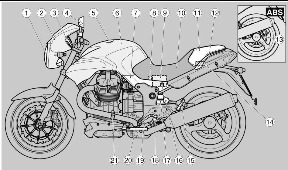
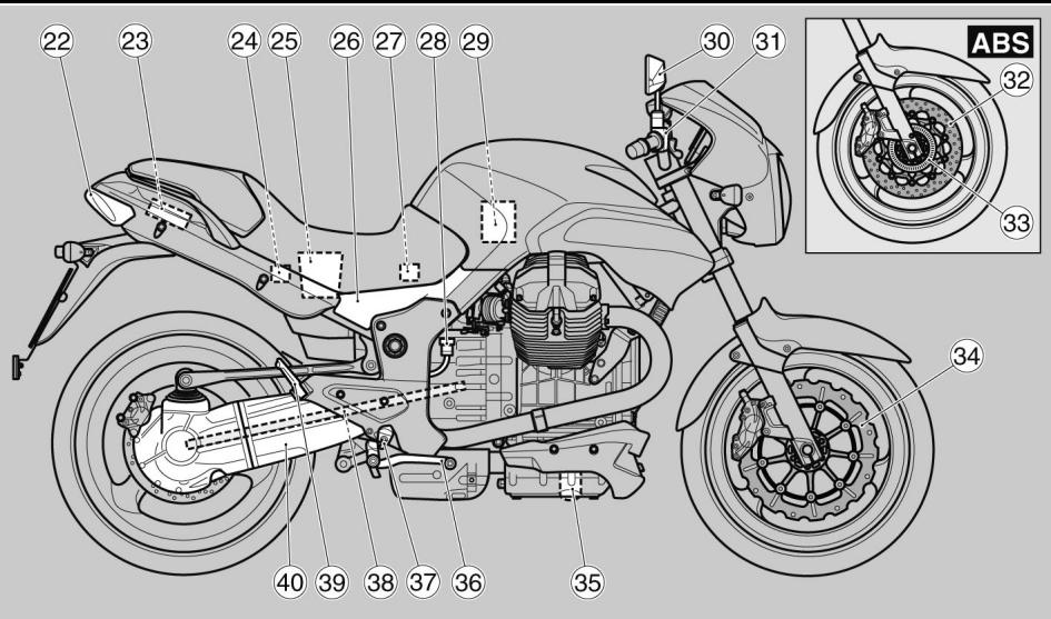
Ubicación componentes principales (02_01, 02_02)
Leyenda:
- Faro delantero
- Cúpula
- Tablero de instrumentos
- Espejo retrovisor izquierdo
- Tapa del deposito combustible
- Deposto combustible
- Carenado lateral izquierdo
- Portafusibles ABS (donde esté previsto)
Arrangement of the main components (02_01, 02_02)
Key:
- Front light
- Top fairing
- Instrument panel
- Rear view mirror left
- Fuel tank cap
- Fuel tank
- Left side fairing
- ABS fuse box (if installed)
-
Battery
-
Batería
- Asiento
- Colin
- Manillar pasajero
- Rueda fònica trasera (donde esté prevista)
- Compartimento ferramentas
- Estribo izquierdo pasajero
- Cerradura del asiento
- Amortiguador triturero
- Estribo izquierdo piloto
- Palanca mando cambio
- Caballete lateral
- Varilla nivel aceite cubo motor
- Faro trasero
- Portaobjetos
- Portafusibles secundarios
- Compartimento portadocumentos
- Carenado lateral derecho
- Portafusibles principales (30A)
- Depóstito liquido freno trasero
- Filtro aire
- Espejo retrovisor derecho
- Depóstito liquido freno delantero
- disco freno delantero ABS (donde esté previsto)
- Rueda fónica (donde esté prevista)
- disco freno delantero
- Filtro de aceite motor
- Palanca mando freno trasero
- Estribo derecho piloto
- Transmisión cardanica
- Estribo correcho pasajero
-
Horquilla monobrazo
-
Saddle
- Passenger seat cover
- Passenger handle
- Rear tone wheel (if installed)
- Tool compartment
- Passenger footrest left
- Saddle lock
- Rear shock absorber
- Driver footrest left
- Gear shift lever
- Side stand
- Engine oil dipstick
- Rear light
- Glove box
- Secondary fuse box
- Document box
- Right side fairing
- Main fuse box (30A)
- Rear brake fluid reservoir
- Air filter
- Rear view mirror right
- Front brake fluid reservoir
- Front brake disc ABS (if installed)
- Tone wheel (if installed)
- Front brake disc
- Engine oil filter
- Rear brake lever
- Driver footrest right
- Cardan shaft transmission
- Passenger footrest right
- Single arm fork
02_03
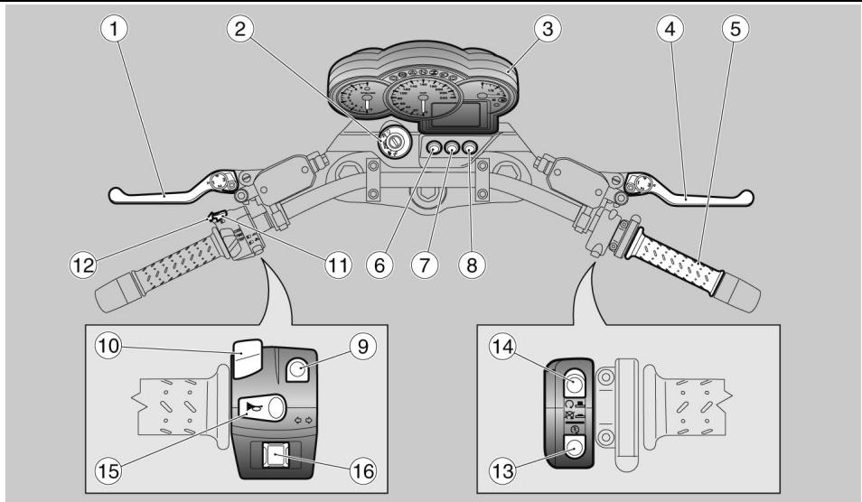
Tablero de instrumentos (02_03)
Leyenda uyubacion mandos / instrumentos
- Palanca mando embrague
- Conmutador encendido / bloqueo del manillar
- Instrumentos eindicadores
- Palanca freno delantero
Dashboard (02_03)
Control element / instrument key
- Clutch control lever
- Ignition switch / steering lock
- Instruments and indicators
- Front brake lever
- Throttle handle
- Emergency flasher button
-
ABS activation / deactivation button
-
Puñaco acelerador
- Pulsador indicator de emergencia
- Pulsador activacion / desactivacion ABS (solo en vehículos equipados con sistemas ABS)
- Pulsador activación / desactivación calefacción puños (donde previsto)
- Conmutador de luces
- Selector unidades pantalla
- Pulsador destello luz de carretera
- Pulsador SET
- Pulsador de arranque
- Pulsador de parada motor
- Pulsador de claxon
- Interruptor intermitentes
(only scooters equipped with ABS system)
- Hand grip heating activation / deactivation button (if equipped)
- Turn signal lights
- Function display selector
- Dipped headlight button
- SET button
- Starter button
- Engine stop button
- Acoustic alarm button
- Turn indicator switch

Cuadro instrumentos análogico (02_04, 02_05, 02_06, 02_07, 02_08)
Leyenda:
- Pantalla digital multifunción (reloj, temperatura ambiente, odómetro, informaciones de viaje, cronómetro, visualización alarmas, indicación de vencimientos deostenimientos)
- Velocimetro
- Cuentarrevoluciones
- Indicador de nivel de combustible
Analog instrument panel (02_04, 02_05, 02_06, 02_07, 02_08)
Key:
- Multifunction digital display (clock, ambient temperature, odometer, trip information, chronometer, alarm display, maintenance expiration indication)
- Speedometer
- Rpm indicator
- Fuel gauge
02_05
02_06
02_07
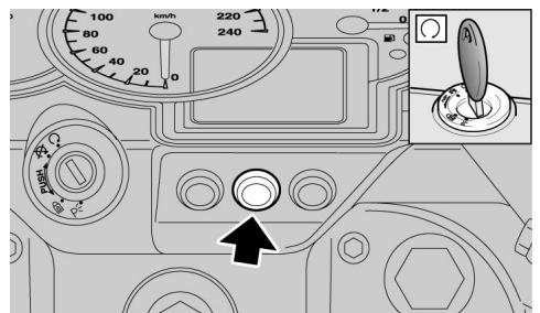
PULSADOR INDICADOS DE EMER-GENcia "HAZARD"
Presionando la tecla, con el tablero encendi-do, se actionan contemporaneamente los quatre intermitentes y los correspondientes testigos en el tablero.
EL HAZARD permanece activo incluso con llave extraída, pero no pueda ser desactivado.
Para desactivar el "Hazard"落户 the conmutador de arranque a la posicion "ON" y presionarNuevoamente el interruptor.
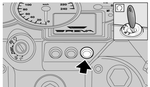
PULSADOR DESACTIVACION ABS (donde estéprevisto)
Para desactivar el sistema, operar como se indica a continuación:
- Llevar el conmutador de encendido a la posicion "ON".
- Apretar ymantener presionado el pulsador.
Pasados uno tres segundos el testigo del cuadro (ABS) empieza a parpadear.
- Soltar el pulsador inmediamente.
- El testigo ABS del instrumento seguirá parpadeando lentamente; por lo tanto el sistema ABS está com
"HAZARD" EMERGENCY TELLTALE LIGHT BUTTON
Pressing the key when the panel is on turns on the four turn indicators and their warning lights on the panel at the same time.
The HAZARD light remains on even with extracted key but it cannot be deactivated.
To deactivate the Hazard light, turn the ignition switch to "ON" and press the switch again.
ABS DEACTIVATION BUTTON (if installed)
To deactivate the system, proceed as follows:
- Turn the ignition switch to "ON" position.
- Press the button and hold it in this position.
After roughly three seconds, the indicator light (ABS) on the instrument panel starts to flash.
- Immediately release the button.
- At this point the ABS indicator light on the instrument panel continues to flash slowly; the ABS system is then
pletamente desactivado.
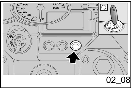
Para reactivar el sistema ABS:
Detener el vehiculo y parar el motor poniendo el conmutador de encendido en posicion "OFF".
- Volver aponer el conmutador de encendido en posicion "ON" y arrancar el motor.
- Ya en marcha, el sistema ABS se volverá a activar al superar los 5 km/h.
completely deactivated.
To activate the ABS system again:
- Stop the scooter and switch off the engine by turning the ignition switch to position "OFF".
- Turn the ignition switch back to position "ON" and start the engine.
- Once switched on, the ABS system will be reactivated only when the speed exceeds 5km/h .

EN CASO DE ANOMALIA O CON ABS DESACTIVADO, LA MOTO SE COMPORTACOMO SI NO ESTUVIERA EQUIPADACON Dicho SISTEMA.

IN CASE OF FAILURE OR WITH ABS DISCONNECTED, THE VEHICLE OPERATES AS IF IT DID NOT HAVE THIS SYSTEM.
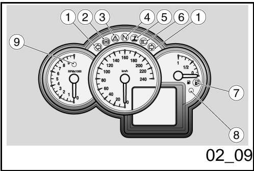
Grupo testigos (02_09)
Leyenda:
- Testigo intermitentes, color verde
- Testigo ABS (Anti-lock Braking System), color amarilloámbar
- Testigo alarma, color rojo
- Testigo cambio en punto muerto (N), color verde
- Testigo caballete lateral bajo, coloramarillo ambar
- Testigo luces de carretera, color
Light unit (02_09)
Key:
- Green turn indicator warning light
- ABS warning light (Anti-lock Braking System), amber yellow
- Red alarm warning light
- Green gear in neutral (N) warning light
- Side stand lowered warning light, amber yellow
- Blue high-beam warning light
azul
- Testigo reserva de combustible, color amarillo ambar
- Testigo antirrobo, color rojo
-
Testigo cambio de marcha, color rojo
-
Amber yellow low fuel warning light
- Red antitheft device warning light
- Red geared shift warning light
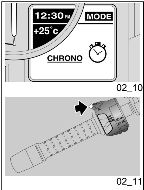
Regulacion de la function cronometro (02_10, 02_11) CRONOMETRO
El cronometro permite, con vehiculo en pista, medir el tiempo por cada giro y memorizar los datos, para que posteriormente poderan ser consultados.
Paraactivar la funciona CRONOMETRO:
- Confirmar la selección en CHRONO con una presión prolongada del pulsador SET.
La pantalla visualiza las siguientesvinciones:
-SALIR
- CRONOMETRAJE
- VISUALIZAR MEDIDAS
- BORRAR MEDIDAS;
Las options peuvent selectionarse en secuencia presionando brevemente el pulsador SET.
Setting the chronometer function (02_10, 02_11)
CHRONOMETER
Upon riding, the chronometer measures the time per revolution and memorises the data, which can be consulted afterwards.
To activate the CHRONOMETER:
- Confirm the selection on CHRONO by holding down the SET button for a couple of seconds.
The following options are shown on the display:
-EXIT
- TIMEKEEPING
- VIEW MEASUREMENTS
- DELETE MEASUREMENTS;
Options can be selected in sequence by pressing the SET button briefly.
- To exit the option, confirm the EXIT
02_12
02_13
02_14
- Para salir de dicha funciona, confirmar la.option SALIR, con una presión prolongada en la tecla SET.
- CRONOMETRAJE
Para activar la funciona CRONOMETRAJE:
Confirmar la selección en CRONOMETRAJE con una presión prolongada del pulsador SET.
La pantalla visualiza la medicación actual y las tres precedentes. A la izquierda de las medicaciones se indica el numero de sesión.
Para起初 el cronometraje:
- Presionar brevemente el pulsador SET.
Ulteriores presiones del pulsador SET durante los primeros 10segundos del inicio del cronometraje, hacer que el cronómetro parta de cero.
Transcurrido dicho periodo, la?sigue prestacion memoriza el dato y hace partir con la?siguefte medicacion.
Presionando prolongamente el pulsador SET, se anula la medicación, y el contagador de la pantalla se pone a cero. Para reinecer la sesión presionar brevemente el pulsador SET.
Para volver a la funciona CRONÓMETRO:
option by holding down the SET button for a couple of seconds.
TIMEKEEPING
To activate the TIMEKEEPING function:
Confirm the selection on TIMEKEEPING by holding down the SET button for a couple of seconds.
The display shows the current measure and the three previous ones. The number of sessions is indicated to the left of the measurements.
To start timekeeping:
Press the SET button briefly.
If the SET button is pressed again during the first 10 seconds after starting timekeeping, the chronometer is reset.
After said period if the button is pressed again, the data is stored and the next measure begins.
If the SET button is held down, the measurement is cancelled and the counter on the display is reset. To start the session again, press the SET button briefly.
To go back to CHRONOMETER:
Hold down the SET button for a
02_15
02_16
02_17
- Presionar prolongadamente el pulsador SET.
ATENCIón
SE PUEDEN MEMORIZAR HASTA 40 SE- SIONES DE CRONOMETRAJE; ULTERIORES MEMORIZACIENCES SOLO SERAN POSIBLES BORRANDO LAS ANTERIORES.
AL QUITAR LA LLAVE TERMINA LA ADQUISICION, EN EL SIGUIENTE ENCENDIDO LA PANTALLA NO VUELVE A LA FUNCION CRONOMETRO SIN EMBARGO LAS MEDIDAS PERMANECEN EN LA MEMORIA, POR LO TANTO LAS SUCESIVAS ADQUISICIONES SERAN ALMACENADAS A CONTINUACION DE LAS ANTERIORES. LOS DATOS MEMORIZADOS SE PIERDEN CUANDO SE DESCONECTA LA BATERIA.
VISUALIZAR MEDICIONES
Estamericano.
Para activar la option VISUALIZAR MEDICIONES:
- Confirmar la selección en "VISUALIZACION MEDICIONES" con una presión prolongada del pulsador SET.
couple of seconds.
CAUTION
UP TO 40 CHRONOMETER SESSIONS CAN BE STORED. FURTHER SESSIONS CAN BE STORED ONLY AFTER DELETING PREVIOUS MEASUREMENTS.
WHEN THE KEY IS EXTRACTED, DATA ACQUISITION STOPS. WHEN THE KEY IS INSERTED AGAIN, THE DISPLAY DOES NOT SHOW THE CHRONOMETER FUNCTION DIRECTLY, BUT THE MEASUREMENTS ARE STORED IN THE MEMORY. THEREFORE, THE SUBSEQUENT ACQUISITIONS WILL BE ADDED TO THE THOSE ALREADY STORED. WHEN THE BATTERY IS REMOVED, ALL STORED DATA IS LOST.
VIEW MEASUREMENTS
This function displays the stored chronometrical times.
To activate the VIEW MEASUREMENTS function:
- Confirm the selection on "VIEW MEASUREMENTS" by holding down the SET button for a couple of seconds.
Para deslizar lasustralianas de las medicaciones:
- Presionar brevemente el pulsador SET.
Para volver a la funciona CRONÓMETRO: - Presionar prolongadamente el pulsador SET.
BORRAR MEDICIONES
Estamericanas.
Para borrar las medicaciones:
- Presionar prolongadamente el pulsador SET.
Confirmar另一边 vez la funciona borrar.
Al finalizar la operationla pantalla vuela a la funciona CRONOMETRO.
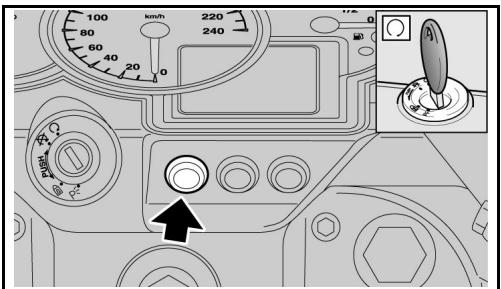
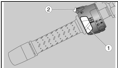
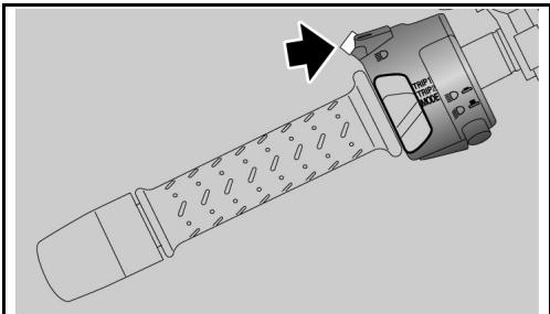
Teclas de mando (02_12, 02_13)
- Selector de tres posiciones: TRIP1 / TRIP2 / MODE
- Pulsador SET; con una presión breve se recorre lasDistinctasfunciñones del MENU; con una presión larga se confirmá la selección.
To scroll the measurement screens:
Press the SET button briefly.
To go back to CHRONOMETER:
Hold down the SET button for a couple of seconds.
DELETE MEASUREMENTS
This function deletes the stored chronometrical times.
To delete the measurements:
Hold down the SET button for a few seconds.
The deletion has to be confirmed twice.
Once the operation is finished, the display shows the CHRONOMETER function.
Control buttons (02_12, 02_13)
- Three position selector switch: TRIP1 / TRIP2 / MODE
- SET button; pressing briefly calls up the function selection in the internal menu, holding the button depressed confirms the selection.
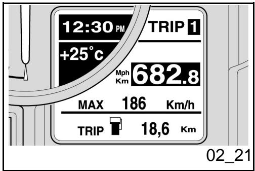
Girar la llave de arranque a la posicion "ON", en la pantalla, durante dos segundos, se muestra la頁ina video de encendido que reproduce el mensaje "Moto Guzzi".
Després del control inicial, en la pantalla aparece la configuración programada en el selector (1).
Las configuraciones seleccionables son:
- TRIP 1
- TRIP 2
-MODE
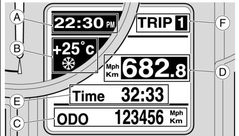
Lasindicacionesque se visualizaniami en lapellalla son:
- RELOJ (zona A)
- TEMPERATURA AMBIENTE (zona B) (cuando la temperatura es menor de 3^ (37^) , en la pantalla, bajo del valor indicado, se visualiza el símbolo del hielo)
- Configuración visualizada (zona F) (TRIP 1, TRIP 2 o MODE).
Losotiortoresmuestraninformacionespecifica decadac configuracion.
By turning the key to "ON", the words "Moto Guzzi" are displayed for two seconds on the ignition screen.
After the initial check, the configuration set on the selector (1) is displayed.
The selectable configurations are:
- TRIP 1
- TRIP 2
-MODE
The indications that are always displayed are:
- CLOCK (A zone)
- AMBIENT TEMPERATURE (B zone) (the ice icon is displayed below the value when the temperature is below 3^ (37^) )
- Displayed configuration (F zone) (TRIP 1, TRIP 2 or MODE).
The other sectors indicate specific information for configuration.
TRIP 1 e 2
TRIP 1 e 2
En las configuraciones TRIP1 y 2 se muestran los datos correspondentes a los parciales de viaje 1 y 2.
Para seleccionar las configuraciones TRIP 1 o TRIP 2:
- Colocar el selector (1) en la posicion correspondiente a la configuracion TRIP que quiera visualizarse.
En el area inferior C de la pantalla se visualiza, independiente del TRIP seleccionado, el totalizador (ODOMETRO), la configuracion se indica en la zona F; en la zona central D se visualiza constantemente la distancia parcial recorrida, finalmente en la zona E se pueda visualizar, a seleccion, los siguientes datos:
- TIEMPO DE RECORRIDO;
- CONSUMO DURANTE EL RECORRIDO;
- CONSUMO INSTANTÁNEO;
- VELOCIDAD MÁXIMA;
- VELOCIDAD MEDIA;
Los datos peuvent selectionarse en secuencia presionando brevemente el pulsador SET (2).
Paraponeracero lasmedicionesparcialedelTRIP seleccionado
- Presionar prolongadamente el pulsoedor SET (2).
The data related to the trip partials 1 and 2 are displayed with TRIP1 and 2 configurations.
To select TRIP 1 or TRIP 2 configuration:
- Move the selector (1) to the position corresponding to the TRIP configuration you wish to display.
The total kilometre ODOMETER is shown on the display C lower zone, regardless the TRIP selected, the configuration indication is displayed on the F zone, the partial distance travelled is constantly displayed on the D central zone, and finally, the following data is displayed upon selection on the E zone:
- TRAVELLING TIME;
- TRIP CONSUMPTION;
- CURRENT CONSUMPTION;
- MAXIMUM SPEED;
-AVERAGE SPEED;
The data can be selected in sequence by pressing the SET button (2) briefly.
To zero set all the partial quantities of the selected TRIP
Hold down the SET button (2) for a few seconds.
If the vehicle has heated hand grips (OPT) and they are active, an icon is shown on the display for the TRIP indication selected,
En caso de haber pueros con sistemas de calefaction (optionals) y si este está activo, en la pantalla, en lugar de la indicacion del TRIP selectionado, aparece el icono correspondiente, cuando que la indicacion del TRIP aparece en la zona de bajo. El icono identifica, en tres niveles, la intensidad del calefaction.
while the TRIP indication is displayed on the area below. The icon identifies three levels of heating intensity.
MODE
La configuración MODE reúne las functiones que permiten que el usuario interactúe con el sistema.
Para ingresar a la direccion MODE:
- Colocar el selector (1) en la pos山坡 MODE.
Haciendo una presión breve del pulsador SET (2) se pueda ver cuestionamente las siguidentes unidades:
- CRONÔMETRO;
- MENU (funciOn excluida con vehiculo en movimiento);
- TENSION DE BATORIA;
MODE
The MODE configuration includes the functions that allow the user to interact with the system.
To go to MODE:
- Move the selector (1) to position MODE.
Pressing the SET button (2) briefly displays the following functions cyclically:
- CHRONOMETER;
- MENU (function disabled with scooter in motion);
-BATTERY VOLTAGE;
Funciones avanzadas (02_14, 02_15, 02_16,
Advanced functions (02_14, 02_15, 02_16, 02_17, 02_18,
02_17, 02_18, 02_19, 02_20, 02_21)
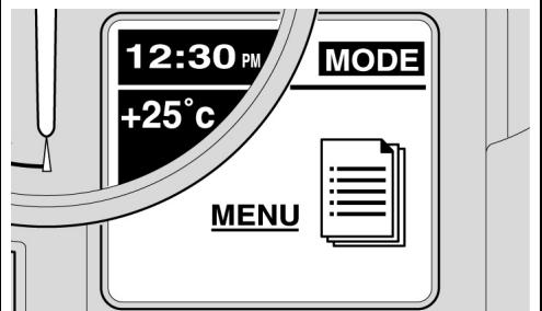
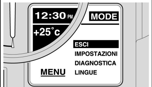
MENU
La funciona peut ser selectionada solo con vehiculo detenido y permite programar la visualizacion de los parametros presentes en las distinctas configuraciones.
Para ingresar a funciOn MENU:
Visualizar la configuración MODE; confirmar la selección en MENU presionando prolongadamente el pulsador SET.
La pantalla visualiza las siguientesvinciones:
-SALIR
- PROGRAMACIONES
- DIAGNOSTICO (función a la que sólo el personal autorizado tiene acces)
-IDIOMA;
Las options peuvent selectionarse en secuencia presionando brevemente el pulsador SET.
02_19, 02_20, 02_21)
MENU
The function can be selected only with the vehicle at a standstill and it sets the parameter display mode in the different configurations.
To access the MENU function:
When the MODE configuration is displayed, confirm the MENU selection by holding down the SET button for a couple of seconds.
The following options are shown on the display:
-EXIT
- SETTINGS
- DIAGNOSIS (function accessed only by authorised personnel)
- LANGUAGE;
Options can be selected in sequence by pressing the SET button briefly.
Con esta función se pueda programar y personalizar la visualización de los parámedos suministrados en lasDistinctas configuraciones.
Para acceder a la funciona PROGRAMACIO-
The display mode of the parameters indicated for the different configurations can be set and personalised with this function.
To go to SETTINGS:
NES:
Confirmar la selección en PROGRAMACIONES presionando prolongamente el pulsador SET.
La Pantalla visualiza las siguientes.optiones:
- SALIR
- AJUSTE HORA
- LIMITE CAMBIO MARCHA
- RETROILUMINACION
-°C/°F - KM/MILLLAS
- 12H/24H
- LED IMMOBILIZER
- MODIFICACION CÓDIGO
Las options peuvent selectionarse en secuencia presionando brevemente el pulsador SET.
Confirm the selection on SETTINGS by holding down the SET button for a couple of seconds.
The following options are shown on the display:
-EXIT
- TIME ADJUSTMENT
-GEAR SHIFT THRESHOLD
- BACKLIGHTING
-°C/°F
- KM/MILES
- 12H/24H
- IMMOBILIZER LED
- CODE MODIFICATION
Options can be selected in sequence by pressing the SET button briefly.
- AJUSTE HORA
Con esta función se pueda ajustar el reloj.
Para acceder a la funciona AJUSTE HORA:
- Confirmar la selección en AJUSTE HORA presionando prolongamente el pulsador SET.
Para ajustar la hora:
TIME ADJUSTMENT
The clock can be adjusted with this function.
To go to TIME ADJUSTMENT:
- Confirm the selection on TIME ADJUSTMENT by holding down the SET button for a couple of seconds.
To adjust the hour:
- El valor de las horas se incrementa en uno con cada presión breve del pulsador SET.
- Con una presión prolongada sobre la tecla SET seoca a la programación de los Minutes; cada presión breve;aumenta el número en uno.
Para memorizar el dato ingresado y volver a la funciona PROGRAMACIONES:
- Presionar prolongadamente el pulso-rador SET.
Every time the SET button is pressed briefly, the hour value increases by one.
- Hold down the SET button for a couple of seconds and the setting turns to minutes, each time the button is pressed briefly increases the number by one.
To store the set data and go back to SETTINGS:
Hold down the SET button for a few seconds.
- LIMITE CAMBIO MARCHA
Con esta función se ingresa el valor limite para el cambio marcha
Para acceder a la funciona LIMITE CAMBIO MARCHA:
- Confirmar la selección en LIMITE CAMBIO MARCHA
- presionando prolongadamente el pulsador SET
En la pantalla se visualiza el mensaje LIMITE CAMBIO MARCHA y en la escala del cuentarrevoluciones se indica el valor recien-tamente programado.
Para programar el valor limite:
- El valor limite se incrementa en 100 rev/min. con cada presión breve del
GEAR SHIFT THRESHOLD
The gear shift threshold can be set in this function.
To go to GEAR SHIFT THRESHOLD:
- Confirm the selection on GEAR SHIFT THRESHOLD by holding down the SET button for a couple of seconds.
The GEAR SHIFT THRESHOLD words are displayed and the threshold value at the time it is set is indicated on the rpm indicator scale.
To set the threshold value:
Every time the SET button is pressed briefly, the threshold value increases by 100 rpm. Once the top
pulsador SET. Alcanzado el limite superior, al presionarNuevoamente SET el valor se resta.
limit is reached, the next time the SET button is pressed, the value is deducted.
Para memorizar el limite programado yolver a la referencia PROGRAMACIONES:
- Presionar prolongadamente el pulso-rador SET.
El valor programado permanece en la memoria hasta lasuma programacion.
ATENCIón
AL SUPERAR Dicho LIMITE EL TESTIGO ROJO DEL CUENTARREVOLUCIONES COMIENZA A PARPADEAR; PARA APAGARLO ES NECESARIO REDUCIR LA VELOCIDAD DEL MOTOR POR DEBAJO DEL LIMITE.
To store the threshold set and go back to SETTINGS:
Hold down the SET button for a few seconds.
The set value is stored in the memory until the following setting.
CAUTION
WHEN THE THRESHOLD IS EXCEEDS THE RED WARNING LIGHT IN THE RPM INDICATOR STARTS TO FLASH. TO TURN IT OFF, BRING THE ENGINE SPEED BACK BELOW THE THRESHOLD LIMIT.
RETROILUMINACION
Estamericano.
Para acceder a la funciona RETROILUMINA-CION:
- Confirmar la selección en RETROLUMINACION presionando prolongadamente el pulsador SET.
La pantalla propone tres niveles de intensidad:
-BAJO
BACKLIGHTING
This function adjusts the brightness of the instrument panel lighting.
To go to BACKLIGHTING:
- Confirm the selection on BACK-LIGHTING by holding down the SET button for a couple of seconds.
The display can show three levels of brightness:
- LOW
-MEAN
-MEDIO
-ALTO
Los niveles peuvent selectionarse en secuencia presionando brevemente el pulsador SET.
Para memorizar el nthel programado y vigor a la funccion PROGRAMACIONES:
- Presionar prolongadamente el pulso-rador SET.
-HIGH
The levels can be selected in sequence by pressing the SET button briefly.
To store the set level and go back to SETTINGS:
Hold down the SET button for a few seconds.
^ C / ^
Estamericana la unidad de medida de la temperatura ambiente.
Para acceder a la funciona ^ C / ^ F
Confirmar la seleccion en C / ^ presionando prolongamente el pulsador SET.
La Pantalla propone dos unidades de medida
-°C
-°F
Las unidades de medida peuvent seleccionarse en secuencia presionando brevemente el pulsador SET.
Para memorizar la escala seleccionada y volver a la funciona PROGRAMACIONES:
Presionar prolongamente el pulsador SET.
^ C / ^
This function selects the ambient temperature unit of measurement.
To go to ^ C / ^ F
Confirm the selection on ^ C / ^ F by holding down the SET button for a couple of seconds.
The display shows the two units of measurement:
-°C
-°F
The units of measurement can be selected in sequence by pressing the SET button briefly.
To store the selected scale and go back to SETTINGS:
Hold down the SET button for a few
seconds.
- KM/MILLAS
Estamericana la unidad de medida de la velocidad.
Para acceder a la funciona "KM/MILLAS":
- Confirmar la selección en KM/ MILLAS con una presión prolongada del pulsador SET.
La pantalla propone las dos unidades de medida
-
KM
-
MILLAS
Las unidades de medida peuvent seleccionarse en secuencia presionando brevemente el pulsador SET.
Para memorizar la selección y volver a la funciona PROGRAMACIONES:
-
Presionar prolongadamente el pulsador SET.
-
12H / 24H
Estamericana la modalidad de visualizacion de la hora.
Para acceder a la referencia 12H/24H:
- Confirmar la selección en
KM / MILES
This function selects the speed unit of measurement.
To go to "KM/MILES":
- Confirm the selection on "KM/MILES" by holding down the SET button for a couple of seconds.
The display shows the two units of measurement:
- KM
-MILES
The units of measurement can be selected in sequence by pressing the SET button briefly.
To store the selection and go back to SETTINGS:
Hold down the SET button for a few seconds.
12H/24H
This function selects the time display mode.
To go to 12H/24H:
- Confirm the selection on "12H/24H" by holding down the SET button for
"12H/24H" presionando prolongamente el pulsador SET.
La pantalla propone dos formatos:
-12H
-24H
Los temas de visualización poden ser selec-cionados en secuencia con una breve presi-isión en la tecla SET.
Para memorizar el formatting selectionado y volver a la funciona PROGRAMACIONES:
- Presionar prolongadamente el pulso-rador SET.
a couple of seconds.
The display shows two formats:
-12H
-24H
The display types can be selected in sequence by pressing the SET button briefly.
To store the selected format and go back to SETTINGS:
Hold down the SET button for a few seconds.
LED INMOVILIZADOR
Esta funciona permite habilar / deshabilitar el destello del led alarma bajo del cuadrante del nivel del combustible. Se usa en caso en que se conecte un antirrobo exterior.
IMMOBILIZER LED
This function enables/disables the alarm LED flashing in the fuel level dial. It is used when the external antitheft device is connected.
- MODIFICACION CÓDIGO
Permite al usuario modificar su propio número personal. Durante el procedimiento sera Solicita la introduccion del viejo número.
RESTABLECIMIENTO CÓDIGO
Permite al usuario programar un nuevo número usuario cuando no se disponga del viejo número. Durante el procedimiento sera solici-
CODE MODIFICATION
Allows users to change their own personal code. During the procedure, the old code will have to be entered.
CODE RESET
Allows users to set a new user code when the old code is not available. During the procedure, 2 of the programmed keys will have
tada la introduccion de 2 llaves de las ya me- to be inserted. morizadas.
DIAGNOSTICO
Esta función se interconecta con los sistemas presentes en la moto y sobre ellos ejecta el diagnóstico. Para habilitarla se debue introducir un número de acceso que solo poseen los centros de assistencia Moto Guzzi.
DIAGNOSIS
This function interfaces with the systems present on the motorcycle and performs the diagnosis on them. To enable this function, enter an access code available only from Moto Guzzi service centres.
SELECTION DEL IDIOMA
dentro de esta funciona se pueda selectionar el idioma de la pantalla.
Para acceder a la funciona IDIOMA:
- Confirmar la selección en IDIOMA presionando prolongamente el pulsador SET.
Losidiomasselectionablesson:
-ITALIANO
- ENGLISH
- FRANCAIS
- DEUTCH
- ESPANOL
Los idiomas peuvent ser seleccionados en secuencia con una breve presión de la tecla SET.
LANGUAGE SELECTION
The display language can be selected with this function.
To go to LANGUAGE:
- Confirm the selection on LAN-GUAGE by holding down the SET button for a couple of seconds.
The languages available are:
-ITALIANO
- ENGLISH
- FRANCAIS
- DEUTSCH
- ESPANOL
The languages can be selected in sequence by pressing the SET button briefly.
To store the selection and go back to LAN-
Para memorizar la selección y volver a la funciona IDIOMA:
- Presionar prolongadamente el pulso-rador SET.
GUAGE:
Hold down the SET button for a few seconds.
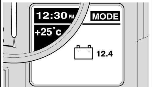
TENSION BATERIA
La funciona muestra la tension de la batería y no permite interactuar con el usuario.
Para acceder a la funciona:
- Con la configuración MODE programada, presionar repetidamente el pulsador SET hasta visualizar la pagina video de Interés.
BATTERY VOLTAGE
This function shows the battery voltage and does not admit interaction with the user.
To access the function:
- When the MODE configuration is set, press the SET button repeatedly until the desired screen is shown.
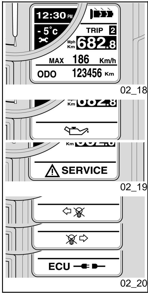
SERVICE
Al vincimiento de los periodos de mantenimiento (después de los primeros 1.000km - 625 millas y a continuación cada 10.000km - 6250 millas) en la pantalla, en la zona del icono del hielo, se visualiza el icono de una llave. Si estuviesenactivados ambos simbo-los, se做不到analternativamente.
SERVICE
When maintenance intervals expire (after the first 1000km - 625 miles, and then after every 10000km - 6250 miles), a wrench icon is displayed on the ice icon area. If both icons are active, they will be displayed alternatively.
VISUALIZACION ALARMAS
En el caso de que se detecte una anomalía grave, que pueda compenser la integridad del vehiculo o de la persona, en la pantalla,
ALARM DISPLAY
If case of a serious failure which jeopardises the integrity of the vehicle or the rider, an icon indicating the cause is displayed on the
en la zona donde normalmente se muestra el odómetro, se visualiza el icono queSEOla la causa de la anomía.
Las alarmas se dividen en dos grupos, según su prioridad:
- Prioridad alta:
Presión aceite, Errores de la centralita, Errores en tablero de instrumentos. - Prioridad baja:
Intermitentes, Desconexión de la centralita.
En el caso se presenten contemporáneamente mas de una alarma de igual prioridad, los iconos correspondientes se visualizan en forma alternada.
Las alarmas de alta prioridad他们在 visualización de las de baja prioridad
KM EN RESERVA
Si el testigo de reserva combustible se enciende en modo continuo, la pantalla indica los kilometros recorridos en esta condicion. El valor se visualiza en la zona donde normalmente se muestra el totalizador (ODOMETRO).
Si se está en la condidón dereshervacuando se arranca el motor,la visualización de loskilómetros recorridos enresherva se producluego de 40segundos del puesta en mar
area where the odometer is generally shown.
The alarms are subdivided into two groups according to their priority:
High priority:
Oil pressure, Control unit errors, Instrument panel errors.
Low priority:
Turn indicators, Control unit disconnected.
If there are more than one alarm of equal priority at the same time, the corresponding icons are displayed alternatively.
High priority alarms inhibit the displaying of low priority alarms.
KM IN RESERVE
When the low fuel warning light is steadily on, the display indicates the kilometres travelled in this condition. The value is displayed in the area where the total kilometre ODOMETER is normally indicated.
If the engine is started with low fuel, the kilometres travelled with low fuel are displayed 40 seconds after the start-up, so that the total kilometre odometer can also be read.
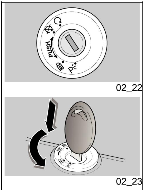
Conmutador de encendido (02_22)
El interruptor de arranque se enquiryra en la placaca superior del manguito de direccion.
Con el vehiculo seentaegan dos llaves (una de reserva).
Las luces se apagan cuando el interruptor de arranque está en «OFF»
NOTA
LA LLAVE ACCIONA EL CONMUTADOR DE ARRANQUE/BLOQUEO DEL MANI-LLAR, LA CERRADURA DE LA TAPA DEL DEPOSITO DEL COMBUSTIBLE Y LA CERRADURA DEL ASIENTO
NOTA
LAS LUCES SE ENCIENDEN AUTOMÁTICAMENTE AL ARRANCAR EL MOTOR.
LOCK: La direccion está bloqueada. No es possible arrancar el motor y acontecer las luces. Se pueda sacar la llave
OFF: El motor y las luces no se pueda poderponer en funcionajo. Se pueda SACAR la llave.
Ignition switch (02_22)
The ignition switch is located on the headstock upper plate.
The vehicle is supplied with two keys (one is the spare key).
The light switch turns off when the ignition switch is set to «OFF».
NOTE
THE KEY ACTIVATES THE IGNITION SWITCH/STEERING LOCK, THE FUEL TANK CAP LOCK AND THE SADDLE LOCK.
NOTE
THE LIGHTS COME ON AUTOMATICALLY AFTER THE ENGINE STARTS.
LOCK: The steering is locked. It is impossible to start the engine or switch on the lights. It is possible to remove the key
OFF: The engine and lights cannot be set to work. It is possible to remove the key.
ON: El motor se puedaponer en functionamiento.No se peut SACAR la llave
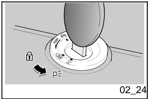
Bloqueo del volante (02_23)
Para bloquear la direccion:
- Girar el manillar Completely hacerla izquierda.
- Girar la llave a la posicion «OFF».
- Presionar y girar la llave en sentido antihorario (hacia la izquierda), virar lentamente el manillar hasta colocar la llave en «LOCK».
- Sacar la llave.
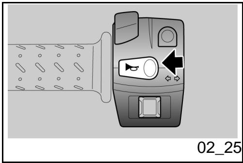
Luces de aparcimiento
(02_24)
El vehiculo está equipado con luces de apar-. candidto delanteras y traseras. Avec que es preferible aparcar el vehiculo en las areas especificas y en Lugares iluminados, las luces de aparcamiento son muy utiles en caso que sea necessario aparcar en un area oscura o poco iluminada, o cuando se desea hacer más visible el vehiculo.
FUNCTIONAMIENTO
Para encender las luces de aparcamento:
- Bloquear la direccion sin extraer la
ON: The engine can be started. It is impossible to remove the key
Locking the steering wheel (02_23)
To block the steering:
- Turn the handlebar completely to the left.
- Turn the key to «OFF».
- Push in the key and turn it anticlockwise (to the left), steer the handlebar slowly until the key is set to position «LOCK».
- Remove the key.
Parking lights (02_24)
The vehicle has front and rear parking lights. Considering that it is preferable to park the vehicle in adequate and well-lit areas, parking lights are very useful when parking the vehicle in a dark or poorly lit area and when the vehicle needs to be visible.
OPERATION
To turn on the parking lights:
- Lock the steering without taking out the key.
- Turn the key to (PARKING) position.
- Check that both parking lights (front
llave.
- Girar la llave a la posicion (PARKING).
- Controller que ambas luces de apar-cimiento (delantera y trasera) se hayan encendido correctamente.
- Quitar la llave.
and rear) are on.
Take out the key.
Pulsante claxon (02_25)
Presionado, pone en funciona el avisador sonoro.
Horn button (02_25)
Press it to activate the horn.
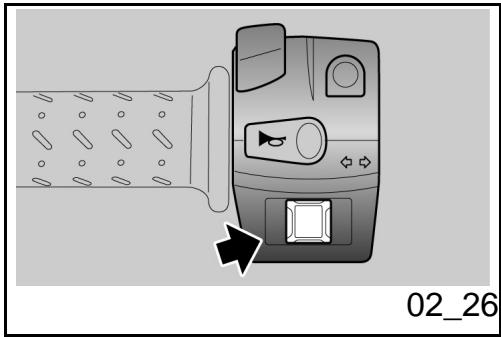
Conmutador intermitentes (02_26)
Para girar hacla izquierda,desplazar el intern-. turtor hacla izquierda;para girar hacla derecha,desplazar el interruptor hacla derecha.Presionar el interruptor para desactivar el intermitente.
ATENCIón
SI EL TESTIGO FLECHAS PARPADEA RÁPIDAMENTE, SIGNIFICIA QUE UNA O
Switch direction indicators (02_26)
Move the switch to the left, to indicate a left turn; move the switch to the right, to indicate a right turn. Pressing the switch deactivates the turn indicator.
CAUTION
IF THE WARNING LIGHT WITH ARROWS FLashes QUICKLY, IT MEANS THAT ONE OR BOTH TURN INDICATORS LIGHT
AMBAS BOMBILLAS DE LOS INTERMI-BULBS ARE BURNT OUT. TENTES ESTÁN QUEMADAS.
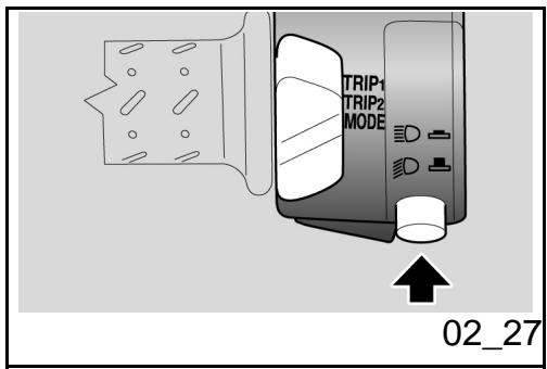
Commutador Iuces (02_27)
Presionando el conmutador de luces se enciende la luz de carretera; al presionarlo-Newamente se enciende la luz de cruce.
High/low beam selector (02_27)
Pressing the light switch turns on the high-beam light; pressing it again turns on the low-beam light.
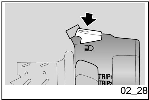
Pulsador rafaga luz de carretera (02_28)
Permite utiliser el destello de la luz de carretera en casos de peligro o emergencia.
Al liberar el pulsador se desactiva el destello de la luz de carretera.
Passing button (02_28)
Uses the high-beam flash in case of danger or emergency.
Releasing the switch deactivates the high-beam flash.
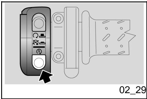
Pulsante arranque (02_29)
Presionando el pulsador, el arrancador pone en funciona el motor.
Start-up button (02_29)
Press the button and the starter motor spins the engine.
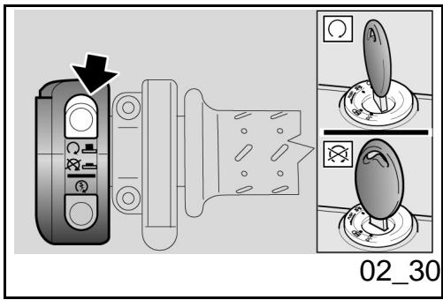
Interruptor parada motor (02_30)
Cuple la función de interruptor de seguidad o de emergencia.
Presionar el interruptor para parar el motor.
Engine stop switch (02_30)
It acts as an engine cut-off or emergency stop switch.
Press this switch to stop the engine.
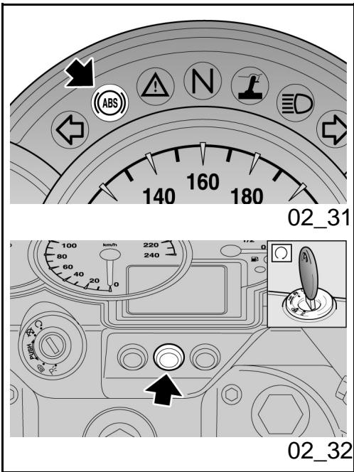
Sistema ABS (02_31, 02_32)
EL ABS es un dispositivo que impide elbloqueo de las ruedas en caso de una frenada de emergencia, augmentando la calidad del vehiculo durante la frenada, respecto de un sistema de frenos tradicional. Cuando secciona el freno, en algunos casos possible producirse el bloqueo del neumatico con una consiguiente perdida de adherencia que ha- ce muy dificultoso el control del vehiculo.Un sensor de posicion "lee" en la rueda fonda, integrada a la rueda del vehiculo, el estado de la mesma, identificando el eventual bloqueo. La indication es controla por una centralita, que regula la presion del circuito de frenos.
NOTA
CUANDO ENTRE EN FUNCIONAMIENTO EL ABS SE ADVIERTE UNA VIBRACION EN LA PALANCA DEL FRENO.

EL SISTEMA DE ANTIBLOQUEO DE LA RUEDA NO RESGUARDA DE UNA CAIDA EN LAS CURVAS. LA FRENADA DE EMERGENCIA, CON EL VEHICULO INCLINADO, EL MANILLAR GIRADO, EL FIRME EN MAL ESTADO, RESBALADIZO O EN CONDICIONES DE ESCASA ADHERENCIa, GENERA UNA CONDIDO N DE INESTABILIDAD MUY DIFICIL DE CONTROLAR. POR LO TANTO SE ACONSEJA
System ABS (02_31, 02_32)
The ABS system is a device to avoid wheels locking in case of emergency braking, increasing vehicle braking stability when compared with a traditional braking system. Sometimes when the brake is pressed, the tyre locks with a consequent loss of grip, which makes it difficult to control the vehicle. A position sensor on the tone wheel, forming an integral unit with the vehicle wheel, "reads" the status of the vehicle wheel spotting any possible lock. A control unit points it out and consequently adjusts the pressure inside the braking circuit.
NOTE
WHEN THE ABS STARTS WORKING, A PULSING IS FELT ON THE BRAKE LEVER.

THE WHEEL ANTILOCK BRAKING SYSTEM DOES NOT PREVENT FALLS WHILE ON A BEND. AN EMERGENCY BRAKING WITH THE VEHICLE INCLINED, HANDLE BAR TURNED, UNEVEN OR SLIPPERY ROADs, OR WITH LITTLE GRIP CREATES LACK OF STABILITY DIFFICULT TO HANDLE. THEREFORE, RIDE CAREFULLY AND SENSIBLY AND ALWAYS BRAKE GRADUALLY. DO NOT SPEED RECKLESSLY, DO NOT DECEIVE YOURSELF WITH AN UNREAL SAFETY. BRAK
CONDUCIR CON PRUDENCIA Y FRENAR EN FORMA GRADUAL. NO CORRER IMPRUMENTENTE AMPARANDOSE EN UNA ILUSORIA SEGURIDAD. LAS FRENADAS EN CURVA ESTAN SUJETAS A PARTICULARES LEYES FISCAS QUE NI SIQUIERA EL ABS PUEDE ELIMINAR.
ING WHILE TURNING A CORNER IS SUBJECT TO LAWS OF PHYSICS WHICH NOT EVEN ABS CAN ELIMINATE.
Al arrancar el motor el testigo ABS permanece encendido hasta que el vehiculo supera los 5km / h . Si el testigo continua encendido significa que se detecto un mal funciona, por lo tanto el ABS se desactiva.
NOTA
EN ESTE CASO DIRIGIRSE A UN CONCESSIONARIO OFICIAL Moto Guzzi.
At engine start-up, the ABS warning light remains on provided that the vehicle does not exceed 5km / h . If the warning light remains on permanently, it means that a malfunction has been detected and that the ABS is not active.
NOTE
IN THIS CASE, CONTACT AN OFFICIAL Moto Guzzi DEALER.
Marcha con sistema ABS activado
El testigo permanece apagado.
Si se detecta un desperf ecto, el testigo se enciende permanentemente para indicar la anomía. Automátamente el dispositivo ABS se desactiva.
NOTA
EN Este CASO DIRIGIRSE A UN CONCESSIONARIO OFICIAL Moto Guzzi.
Riding with an active ABS system
The warning light remains off.
If a failure is found, the warning light turns on permanently to indicate the malfunction. The ABS device is automatically deactivated.
NOTE
IN THIS CASE, CONTACT AN OFFICIAL Moto Guzzi DEALER.
Marcha con sistema ABS no activado
El testigo parpadea; el sistema ha sido desactivado voluntariamente.
Desactivación dispositivo ABS
Se peut desactivar el sistema ABS accionando el interruptor
Riding with a disabled ABS system
The warning light flashes, the system has been deactivated deliberately.
ABS device deactivation
Deactivate the ABS system with the switch

LA MOTO TIENE UN ABS DE DOS CANALES, ES DECIR QUE ACTUA TANTO SOBRE LA RUEDA DELANTERA COMO SOBRE LA RUEDA TRASERA. ES IMPORTANTE CONTROLAR QUE SIempre LA RUEDA FONICA ESTE LIMPIA, Y PERIODICAMENTE CONTROLAR QUE LA DISTANCIA CON EL SENSOR SEA CONSTANTE EN LOS 360 GRADOS. ES MUY IMPORTANTE TAMBIEN CONTROLAR NUEVAMENTE, EN CASO DE DESMONTAJE Y MONTAJE DE LA RUEDA DELANTERA, QUE LA DISTANCIA ENTRE LA RUEDA FONICA Y EL SENSOR SEA LA PREVISTA. PARA EL CONTROL Y LA REGULACION DIRIGIRSE A UN TALLER AUTORIZADO Moto Guzzi.

CON EL SISTEMA ABS, LAS PASTILLAS

THE MOTORCYCLE HAS A TWO CHANNEL ABS, THAT IS, IT WORKS EITHER ON THE FRONT OR THE REAR WHEEL. ALWAYS CHECK THAT THE TONE WHEEL IS CLEAN, AND REGULARLY CHECK THAT THE DISTANCE TO THE SENSOR IS CONSTANT ON ALL 360 GRADES. SHOULD THE FRONT WHEEL BE REMOVED AND REFIT, IT IS VERY IMPORTANT TO CHECK ALSO THAT THE DISTANCE BETWEEN THE TONE WHEEL AND THE SENSOR IS THE ONE SPECIFIED. FOR CHECKING AND ADJUSTMENT, CONTACT AN AUTHORISED Moto Guzzi WORKSHOP.

WITH AN ABS SYSTEM, BRAKE PADS WITH NON-HOMOLOGATED FRICTION MATERIAL CAN COMPROMISE THE COR
DE FRENO CON MATERIAL DE FRIECION NO HOMOLOGADOS, PERJUDICAN EL CORRECTO FUNCIONAMENTO DE LA FRENADA, DISMINUYENDO DRASTICAMENTE LA SEGURIDAD DE LA CONDUCCION.
RECT BRAKING, REDUCING RIDING SAFETY SIGNIFICANTLY.
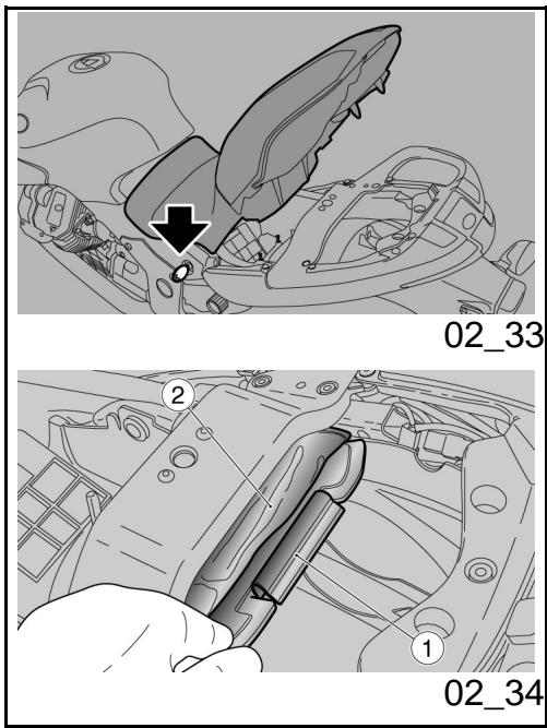
Abertura sillín (02_33)
- Colocar el vehiculo sobre el caballete.
- Introducir la llave en la cerradura del asiento.
Girar la llave en sentido horario, levantar y sacar el asiento
Para bloquear el asiento:
- Positionar la parte delantera del asiento en su alojamento y bajo la parte trasera.
- Presionar en la parte trasera, hasta que enganche la cerradura.
ATENCLON
ANTES DE BAJAR Y BROQUEAR EL ASIENTO, CONTROLAR DE NO HABER OLVIDADO LA LLAVE EN EL COMPARTI-MIENTO PORTADOCUMENTOS/KIT HERRAMIENTAS.

ANTES DE CONDICIR ASEGURARSE DE
Opening the saddle (02_33)
Rest the vehicle on its stand.
- Introduce the key in the saddle lock.
- Turn the key clockwise, lift and remove the saddle afterwards
To lock the saddle:
- Place the saddle front part in its seat and lower the rear part.
- Press the rear part to trip the lock.
CAUTION
BEFORE LOWERING AND LOCKING THE SADDLE, CHECK THAT THE KEY HAS NOT BEEN LEFT IN THE GLOVEBOX / TOOL KIT COMPARTMENT.

BEFORE RIDING, MAKE SURE THAT THE SADDLE IS CORRECTLY LOCKED.
QUE EL ASIENTO ESTÉ CORRECTAMENTE BLOQUEADO.
Compartmento porta-doc./kit herramentas (02_34)
Para acceder al compartimento portadocumentos:
Extraer el asiento.
Para acceder al组成部分 kit herram-. mientes:
Extraer la tapa (1).
Extraer el sobre (2) del alojamento.
Glove/tool kit compartment (02_34)
To access the glovebox:
- Remove the saddle.
To access the tool kit compartment:
- Remove the cover (1).
- Extract the case (2) from its seat.
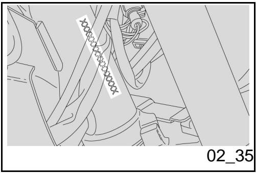
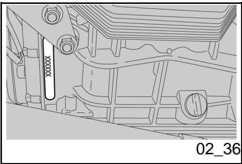
La identificacion (02_35, 02_36)
Es convenienteayar notable de los nombres del chasis y del motor, en el espacio reservado para los mismos en el presente manual. El número de chasis pueda serutil para adquirir las piezas de repuesto.
ATENCIón

LA ALTERACION DE LOS NUMEROS DE IDENTIFICACION PUEDE ACARREAR
Identification (02_35, 02_36)
Write down the chassis and engine number in the specific space of this manual. The chassis number is handy when purchasing spare parts.
CAUTION

CHANGING THE IDENTIFICATION NUMBERS IS AN OFFENCE WHICH CAN RESULT IN SEVERE CRIMINAL AND ADMINISTRATIVE CHARGES. ANY CHANGE TO
GRAVES SANCIONES PENALES Y ADMINISTRATIVAS. EN PARTICULAR, LA ALTERNACION DEL NUMERO DE CHASIS IMPLICA LA INMEDIATA CADUCIDAD DE LA GARANTIA
THE CHASSIS NUMBER IN PARTICULAR MAKES THE GUARANTEE NULL AND VOID
NUMERO DE CHASIS
El número de chasis está estampillado en el manguito de direccion, bajo derecho.
Chasis ^
CHASSIS NUMBER
The chassis number is stamped on the right side of the headstock.
Chassis No.
NUMERO DE MOTOR
El número de motor está estampillado en la bancada del carter motor bajo izquierdo.
Motor n°
ENGINE NUMBER
The engine number is printed on the base of the left side engine crankcase.
Engine No.
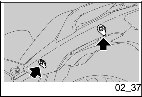
Fijación maletero (02_37)
Sobre la parte trasera del asiento se pueda fazer un peuño equipaje, ajustándolo con los elásticos, que se fisjarán en los 4 enganches (2 para cada lado).
Peso maximalo permitted: 5kg
ATENCLON
EL EQUIPJAJE DEBE SER DE DIMENSIONES REDUCIDAS Y ESTAR SUJETADO FIRMEMENTE.
Luggage anchor point (02_37)
A small piece of luggage can be fastened on the rear part of the saddle using the elastic straps that are secured to the 4 anchoring hooks (2 per side).
Maximum weight allowed: 5kg
CAUTION
CARRY ONLY Luggage WITH ADEQUATE DIMENSIONS AND SECURE IT
1200 sport


Cap. 03
El uso
Chap. 03
Use
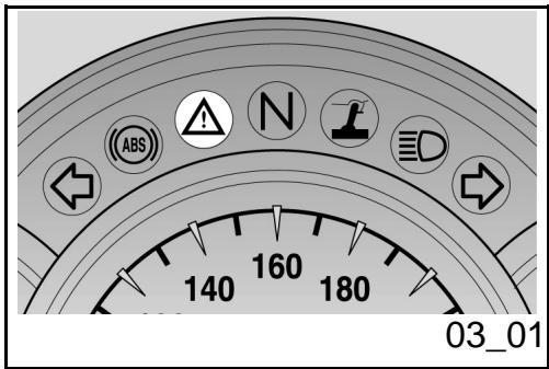
Controles (03_01)
ATENCLON
ANTES DE SALIR, EFFECTUAR SIEMPRE UN CONTROL PRELIMINAR DEL VEHICULO, PARA GARANTIZAR UN FUNCIONAMIENTO CORRECTO Y SEGURO. EL HECHO DE NO REALIZAR DICHAS OPERACIONES PUEDE CAUSAR GRAVES LESIONES PERSONALES O DANOS GRAVES AL VEHICULO. SI NO SE COMPRENDE EL FUNCIONAMIENTO DE ALGUN MANDO O EN EL CASO DE QUE SE DETECTE O SE SOSPECHE DE ALGUN ANOMALIA, NO VACILAR EN DIRIGIRSE A UN CONCESSIONARIO OFICIAL GUZZI. EL TIEMPO NECESARIO PARA UN CONTROL ES MUY BREVE Y RESULTA MUY VENTAJOSO PARA LA SEGURIDAD.
Checks (03_01)
CAUTION
BEFORE RIDING, ALWAYS PERFORM A PRELIMINARY CHECK OF THE VEHICLE, FOR CORRECT AND SAFE OPERATION. FAILURE TO DO SO MAY LEAD TO SEVERE INJURY OR VEHICLE DAMAGE. DO NOT HESITATE TO CONTACT AN OFFICIAL MOTO GUZZI DEALER IF YOU DO NOT UNDERSTAND HOW SOME CONTROLS WORK OR IF MALFUNCTIONING IS DETECTED OR SUSPECTED. THE TIME REQUIRED TO CARRY OUT A CHECK IS EXTREMELY SHORT BUT THIS RESULTS IN A SIGNIFICANT ENHANCED SAFETY.
Estevehicleostapepreparadoparaidentificar, en tiemporeal, eventuales anomalías defuncioncimiento,memorizadas porla centralitaelectrónica.
Cada vez que el conmutador de arranque se positionala en "ON", en el tablero se enciende, durante aproximamente tres segundos, el testigo LED alarma.
This vehicle has been programmed to indicate in real time any operation failure stored in the electronic control unit memory.
Every time the ignition switch is turned to "ON", the alarm LED warning light turns on for about three seconds on the instrument panel.
CONTROLES PRELIMINARES
| Characterística | Descripción/Valor |
| Freno de disco delantero ytrasero | Controlar el funcionaimiento, la carrera en vacío de las palancas de mando, el nivel del liquido y eventuales perdidas. Controlar el desgaste de las pastillas. Si es必須o efectuar el lienado del liquido de frenos. |
| Accelerador | Controlar que funciona con suavidad y que se pueda abrir y cerrar Completely, en todas las posiciones de la direction. Regular y/o lubricar si es必須ario. |
| Aceite motor | Controlar y/orestaurant el nivel si es必須ario. |
| Ruedas/neumáticos | Controlar el estado superficial de los neumáticos, la presión de inflado, el desgaste y eventuales daños.Quitar eventuales cuerpos extraños encastrados en las esculturas de la banda de rodadura. |
| Palancas de los frenos | Controlar que funciona con suavidad. |
PRE-RIDE CHECKS
| Specification | Desc./Quantity |
| Front and rear disc brake | Check for proper operation. Check brake lever free play and brake fluid level. Check for leaks. Check the brake pad wear. If necessary top-up with brake fluid. |
| Throttle grip | Check it functions smoothly and that it can be fully opened and closed in all steering positions. Adjust and/or lubricate if necessary. |
| Engine oil | Check and/or top up as required. |
| Wheels/tyres | Check that tyres are in good conditions, check inflation pressure, tyre wear and possible damage. Remove any possible strange body that might be stuck in the tread design. |
| Brake levers | Check they function smoothly. Lubricate the joints and adjust the stroke if necessary. |
| Clutch | Check for proper operation. Check clutch lever free play and fluid level. Check for leaks. If |
| Lubricar las articulaciones y regular la carrera si es Neededo. | |
| Embrague | Controlar el funciona, la carrera en vacío de la palanca de mando, el nivel del liquido y eventuales perridas. Si esneededario, efectuar el llenado del liquido: el embragueDebeFuncurar sin tironeos ni deslizamente. |
| Dirección | Controlar que el giro se realice en forma homogenea, que se deslice y que noonga juego oaflojamente. |
| Caballete central - lateral | Controlar que funciona.Comprobar que el caballete bajo y suba sin roces y que el tensado de los muelles lo returne a su posición normal. Lubricar los acoplamente y las articulaciones si esnecessary. Controlar el correcto funciona del interruptor de seguridad. |
| Elementos de fijación | Controlar que los elementos de fijación no se estén flojos.Eventualmente, regular oapurar. |
| Depósito combustible | Controlar el nivel y reabastecer si es需要用. |
| needed, top up the fluid; the clutch must work without gripping and/or sliding. | |
| Steering | Check that the rotation is homogeneous, smooth and there are no signs of clearance or slackness. |
| Centre - side stand | Check its operation. Check that there is no friction when the side stand is pulled up and down and that the springs' tension makes it snap back to its rest position. Lubricate couplings and joints if necessary. Check the safety switch for correct operation. |
| Fasteners | Check that he clamping elements are not loose. If necessary, adjust or tighten them. |
| Fuel tank | Check the coolant level and refill if necessary. Check the circuit for possible leaks or obstructions. Check that the tank cover closes correctly. |
| Engine stop switch (ON - OFF) | Check for correct operation. |
| Controlar las eventuales perdidas u occlusiones del circuito. Controlar que el tapón de combustible está correctamente cerrado. | |
| Interruptor de parada del motor (ON - OFF) | Controlar el funcionacorrecto. |
| Luces, testigos, avisador sonoro, interruptores luz de stop trasera y dispositivos electricos | Controlar el funcionacorrecto de los dispositivos soneros y visuales. Sustituir las bombillas o intervir en caso de avería. |
| Aceite de transmisión - Guzzi | Controlar. Si Fuera Needede llenado dirigirse a un taller autorizado Moto Guzzi. |
| Ruedas fónicas (sólo para vehículos equipados con sistemas ABS) | Controlar que las ruedas fónicas esténperfectamente limpias |
| Lights, warning lights, horn, rear stop light switch and electrical devices | Check the correct operation of the horn and lights. Replace the bulbs or repair any malfunctions. |
| Transmission oil - Guzzi | Check. If topping up is necessary, contact an authorised Moto Guzzi workshop. |
| Tone wheels (only for vehicles with ABS system) | Check that the tone wheels are perfectly clean |
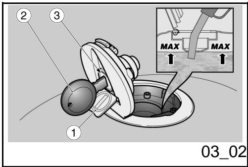
Abastecimiento (03_02)
Para reabastecer de combustible:
Levantar la tapa (1).
- Introducir la llave (2) en la cerradura de la tapa del deposito (3).
Girar la llave en sentido horario, tirar yAbrir la tapa del combustible.
Capacidad del deposito (incluya laresherva) 23litros
Reserva del deposito: 4 litros
Reabastcer.

NO AGREGAR ADITIVOS U OTRAS SUSTANCIAS AL COMBUSTIBLE.
SI SE USA UN EMBUDO U OTRO OBJECTO, ASEGURARSE DE QUE ESTÉ PERFECTAMENTE LIMPIO.

NO LLENAR COMPLETAMENTE EL DEPOSITO; EL NIVEL MAXIMO DE COMBUSTIBLE DEBE PERMANECER POR DEBAJO DEL BORDE INFERIOR DEL COLECTOR (VER FIGURA).
efectuado el reabastecimiento:
Refuelling (03_02)
To refuel:
- Lift the cover (1).
- Introduce the key (2) in the fuel tank cap lock (3).
- Turn the key clockwise, pull and open the fuel cap.
Fuel tank capacity (including reserve): 23 litres
Tank reserve: 4 litres
Refuel.

DO NOT ADD ADDITIVES OR ANY OTHER SUBSTANCES TO THE FUEL.
WHEN USING A FUNNEL OR ANY OTHER ELEMENT, MAKE SURE IT IS PERFECTLY CLEAN.

DO NOT FILL THE TANK UP TO THE RIM; FUEL MAXIMUM LEVEL MUST ALWAYS BE BELOW THE LOWER EDGE OF THE FILLER NECK (SEE FIGURE).
after refuelling:
- El cierre de la tapa es possible solo introduciendo la llave (2).
- Con la llave (2) introducida, cerrar la tapa, presionándola.
Extraer la lave (2). -
Volver a cerrar la taps (1).
-
The cap can only be closed if the key (2) is inserted.
- Once the key (2) is inserted, press to close the cap again.
- Extract the key (2).
- Close the cover (1) again.

ASEGURARSE DE QUE LA TAPA ESTÉ CORRECTAMENTE CERRADA.

MAKE SURE THE CAP IS TIGHTLY CLOSED.
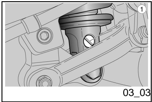
Regulación amortiguadores traseros (03_03, 03_04)
La suspENSION trasera esta compuesta por el grupo muelle-amortiguador, que se conecta mediante silent-block, al chasis y por medio de articulaciones de levas, a la horquilla trasera.
Para regular el ajuste del vehiculo, el amortiguidor consta de:
- un dispositivo de ajuste roscado (1) para regular el frenado hidráulico en extension;
- un dispositivo de ajuste con mecanismo (2) para regular la precarga del muelle (3).
Rear shock absorbers adjustment (03_03, 03_04)
The rear suspension consists of a springshock absorber unit linked to the frame via silent-block and to the rear fork via a linkage system.
To set the vehicle suspension, the shock absorber has:
- a set screw (1) to adjust the hydraulic rebound damping;
- a set knob (2) for spring (3) preloading adjustment.
REGULACION TRASERO
DEL AMORTIGUADOR
REAR SHOCK ABSORBER ADJUSTMENT
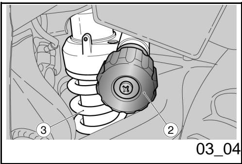
La programación estándar del amortiguidor trasero ha sido previsto para satisfacer la mayoría de las conditiones de conducccion a velocidad moderada o elevada, para el transporte del conductor con equipaje.
Sin embargo es possible personalizar la regulacion en referencia del uso del vehiculo.

ANTES DE OPERAR EN LOS DISPOSITIVOS DE AJUSTE, ESPERAR QUE EL MOTOR Y EL SILENCIADOR DE ESCAPE SE HAYAN ENFRIADO COMPLETAMENTE.
Standard rear shock absorber setting is adjusted to suit most high and low speed riding conditions, to transport the rider plus luggage.
However, this set can be modified for specific needs according to vehicle use.

ALLOW ENGINE AND EXHAUST SILENCER TO COOL DOWN BEFORE OPERATING THE SET SCREWS.
TIPOS DE REGULACION
Regulación normal (estándar):
-soleo conductor.
Regulación cargo media:
- (por exemple: conductor con pasajero o con equipaje).
Regulación Tmaxima carga:
- (por exemple: conductor, pasajero y equipajes).
ATENCIón
REGULAR LA PRECARGA DEL MUELLE Y EL FRENADO HIDRAULICO EN EXTENSION DEL AMORTIGUADOR SEGUN LAS CONDICIONES DE USO DEL VEHICULO.
ADJUSTMENTS
Regular adjustment (standard):
- only rider.
Half load adjustment:
- (for example, rider with passenger or with luggage).
Maximum load adjustment:
- (for example, rider, passenger and luggage).
CAUTION
SET THE SPRING PRELOADING AND THE REBOUND DAMPING OF THE SHOCK ABSORBERS ACCORDING TO THE VEHICLE USE CONDITIONS. IF THE SPRING PRE
AUMENTANDO LA PRECARGA DEL MUE LLE, TÁMBIÉN SE DEBE AUMENTAR EL FRENADO HIDRAULICO EN EXTENSION DEL AMORTIGUADOR, PARA EVITAR IMPROVISOS REBOTES DURANTE LA CONDUcción. EN ESTE CASO DIRIGIRSE A UN CONCESSIONARIO OFICIAL Moto Guzzi. PROBAR REPETIDAMENTE EN VEHICULO EN CARREtera HASTA OBTENER LA REGULACION OPTIMA.
LOADING IS INCREASED, IT IS NECESSARY TO INCREASE THE REBOUND DAMPING ACCORDINGLY TO AVOID SUDDEN JERKS WHEN RIDING. IF NECESSARY, CONTACT AN OFFICIAL Moto Guzzi DEALER. TRY RIDING THE VEHICLE ON THE STREET UNTIL THE OPTIMUM ADJUSTMENT IS OBTAINED.
TABLE DE REGULACION DEL AMORTIGUADOR
Los calibrados para energia normal corresponden al estandar de fabrica
SHOCK ABSORBER SETTING TABLE
Regular load adjustments are the standard settings by manufacturer
REGULACION DEL AMORTIGUADOR TRASERO
| Característica | Descripción/Valor |
| Precarga -CONDITIONES DE CARGANormal | 8lick para descarga completa(soft) |
| Precarga -CONDITIONES DE mediacarga | 35lick para descarga completa(soft) |
| Precarga -CONDITIONES dmáxima@carga | completamente enroscado |
| Extensión -CONDITIONES DE caragornormal | 14lick partiendo de tornillo (1)completamente cerrado |
REAR SHOCK ABSORBER ADJUSTMENT
| Specification | Desc./Quantity |
| Preload - regular load conditions | 8 clicks from completely unloaded (soft) |
| Preload - half load conditions | 35 clicks from completely unloaded (soft) |
| Preload - maximum load conditions | completely screwed |
| Rebound - regular load conditions | 14 clicks starting from screw (1) fully tightened |
| Extension -CONDITIONES DE media cargo | 11lick partiendo de tornillo (1)completamente cerrado |
| Extension -CONDITIONES de maximalacarga | 8lick partiendo de tornillo (1)completamente cerrado |
| Rebound - half load conditions | 11 clicks starting from screw (1) fully tightened |
| Rebound - maximum load conditions | 8 clicks starting from screw (1) fully tightened |
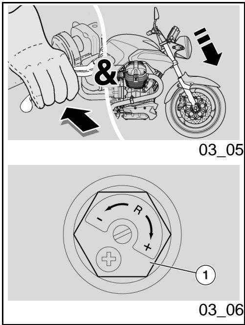
Regulación horquilla delantera (03_05, 03_06, 03_07)
ATENCIón
PARA EL CAMBIO DEL ACEITE HORQUILLA DELANTERA Y DE LOS RETENES DE ACEITE, DIRIGIRSE A UN CONCESIONARIO OFICIAL Moto Guzzi.
Con la palanca del freno delantero actionada, presionar repetidamente en el manillar, empujando a fondo la horquilla. La carrera debe ser suave y los vastosos no deben evideciar marcas de aceite.
Controlar el ajuste de todos los organismos y el funcionaimiento de las articulaciones de la suspensión delantera y trasera.
REGULACION DE LA HORQUILLA
Los calibrados para energia normal correspond
Front fork adjustment (03_05, 03_06, 03_07)
CAUTION
FOR REPLACEMENT OF THE FRONT FORK OIL AND OIL SEALS, PLEASE CONTACT AND OFFICIAL Moto Guzzi DEALER.
Operating the front brake lever, press the handlebar repeatedly to send the fork to the fully down. The stroke should be soft and there should be no oil marks on the stems.
Check the tightening of all the elements and the correct operation of the front and rear suspension joints.
FORK SETTING
Normal load adjustments are the standard
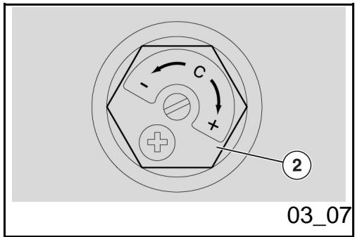
den al estándar de fabrica.
- Regulación hidráulica en extension (Drcha.): 7 niveles desde cierre total (1).
- Regulación hidráulica en compresión (Izq.): 7 niveles desde cierre total (2).
ATENCIón
Paraatarelnumborende nivelesde los registros de regulacion (1-2),empezar siempredesala posicionmasrigida (girocomplete del registro en el sentido delasagujas del reloj),hastaunmaximo de15 niveles.Girargraduallyntelos registros de regulacion(1-2),aumentandounamarca cada vez.
settings by manufacturer:
- Hydraulic adjustment when extended (right): 7 releases, all closed (1).
- Hydraulic adjustment when compressed (left): 7 releases, all closed (2).
CAUTION
To count the release number of the adjustment range (1-2), always start from the most rigid setting (adjuster turned fully in clockwise direction), counting a maximum of 15 releases. Turn the adjuster slowly (1-2), one step at a time.
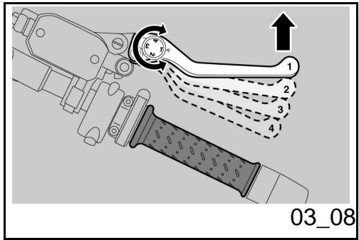
Regulación leva frenodelantero (03_08)
Se puede regular la distancia entre los extremos de la palanca y el puño, girando el dispositivo.
Las posiciones "1" y "4" corresponden a una distancia aproximada, entre el extremo de la palianca y del puno, Respectivamente de 105 y 85 mm.
Las posiciones "2" y "3" corresponden a distancias intermedias.
Para la regulación: empujar la palianca de
Justering af greb til forbremse (03_08)
Adjust the distance between the lever end and the hand grip by turning the set screw.
Positions "1" and "4" correspond to a lever end-hand grip distance of about 105 and 85 mm respectively.
Positions "2" and "3" correspond to intermediate distances.
To adjust: push the control lever forward and turn the set screw until the arrow points at the desired number.
mando hacía adelante y girar el dispositivo hasta que el valor deseado se corresponda con la flecha de comprobación.
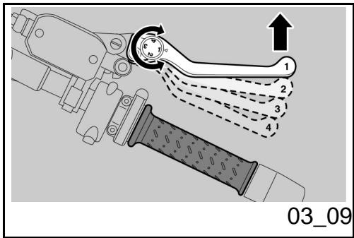
Regulación leva embrague (03_09)
Se puede regular la distancia entre los extremos de la palanca y el puno, girando el dispositivo.
Las posiciones "1" y "4" corresponden a una distancia aproximada, entre el extremo de la palanca y del puno, Respectivamente de 105 y 85 mm.
Las posiciones "2" y "3" corresponden a distancias intermedias.
Para la regulación: empujar la palanca deMANDo hacía adelante y girar el dispositivo hasta que el valor deseado se corresponda con la flecha de comprobación.
Clutch lever adjustment (03_09)
Adjust the distance between the lever end and the hand grip by turning the set screw.
Positions "1" and "4" correspond to a lever end-hand grip distance of about 105 and 85 mm respectively.
Positions "2" and "3" correspond to intermediate distances.
To adjust: push the control lever forward and turn the set screw until the arrow points at the desired number.
Rodaje
El rodaje del motor es fundamental para garantizar la duración y el correcto funciona del mesmo. Recorrer, si es posible, carreteras con muchas curvas y/o pendentes para someter el motor, las suspENSIONes y los frenos a un rodaje más eficaz. Cambiar la velocidad de conducccion durante el roda
Running in
Engine run-in is essential to ensure engine long life and correct operation. Twisty roads and gradients are ideal to run in engine, brakes and suspensions effectively. Vary your driving speed during the run-in. In this way, you allow for the work of components to be "loaded" and then "unloaded", thus cool-
je. De este modo se permite "cargar" el trabajo de los componentes y sucesivamente "descargarlo", enfriando las piezas del motor.
ATENCIón
ES POSIBLE QUE DEL EMBRAGUE SE DESPRENDA UN LEVE OLOR DE QUEMADO, DURANTE EL PRIMER PERIODO DE USO. ESTE FENOMENO ES PERFECTAMENTE NORMAL Y DESAPARECERA APENAS LOS DISCOS DEL EMBRAGUE TENGAN UN POCO DE USO.
SI BIEN ES IMPORTANTE FORZAR LOS COMPONENTES DEL MOTOR DURANTE EL RODAJE, PRESTAR MUCHA ATENCION PARA NO EXCEDERSE.
ATENCIón
SÓLO DESPUÉS DE HABER EFFECTUADO EL CONTROL PERÍODICO DE FINALIZACION DEL RODAJE ES POSIBLE OBTENER LAS MEJORES PRESTACIONES DEL VEHICULO.
ing the engine parts.
CAUTION
THE CLUTCH MAY EMIT A SLIGHT BURNING SMELL WHEN FIRST USED. THIS PHENOMENON SHOULD BE CONSIDERED NORMAL AND WILL DISAPPEAR AS SOON AS THE CLUTCH DISCS GET ADAPTED.
IT IS IMPORTANT TO STRAIN ENGINE COMPONENTS DURING RUN-IN, HOWEVER, MAKE SURE NOT TO OVERDO THIS.
CAUTION
ONLY AFTER THE SERVICE AT THE END OF THE RUN-IN PERIOD, IT IS POSSIBLE TO ATTAIN THE BEST PERFORMANCE OF YOUR VEHICLE.
Atenerse a lassiguientesindicaciones:
- No acelerar repentina y Completely cuando el motor está en marcha con un bajo régimen de revoluciones, tanto durante como antes del rodaje.
- Durante los primeros 100km (62
Follow the guidelines detailed below:
- Do not twist the throttle grip abruptly and completely when the engine is working at a low revs, either during or after run-in.
During the first 100km (62 miles) step carefully on the brakes to avoid
millas), acontecer con prudencia los frenos para evaporar frenadas bruscas y prolongadas. Esto permite un correto ajuste del material de friccion de las pastillas en los discos del freno.
rough and long braking. That is to permit the adequate adjustment of the pad friction material to the brake discs.

AL ALCANZAR EL KILOMETRAJE PREVISTO, DIRIGIRSE A UN CONCESIONARIO OFICIAL Moto Guzzi PARA QUE EJECUTE LOS CONTROLES CONTEMPLADOS EN LA TABLA "FIN DEL RODAJE" DE LA SECCION MANTENIMIENTO PROGRAMADO, CON LA FINALIDAD DE EVITAR DANOS A LAS PERSONAS O AL VEHICULO.

AFTER THE SPECIFIED MILEAGE,TAKE THE VEHICLE TO AN OFFICIAL Moto Guzzi DEALER FOR THE CHECKS INDICATED IN THE "AFTER- RUN" TABLE IN THE SCHEDULED MAINTENANCE SECTION TO AVOID INJURING YOURSELF, OTHERS AND /OR DAMAGING THE VEHICLE
Aparcamento
Es muy importante elegir la zona de aparcimiento y Respectar las señales viales y lasindicaciones que se mentionan a continua.
ATENCIón
APARCAR EL VEHICULO SOBRE UN TERRENO SOLIDO Y PLANO PARA EVITAR QUE SE CAIGA.
NO APOYAR EL VEHICULO EN LAS PAREDES Y NO ACOSTARLO EN EL PAVI
Parking
It is very important to select an adequate parking spot, in compliance with road signals and the guidelines described below.
CAUTION
PARK ON SAFE AND LEVEL GROUND TO PREVENT THE vehicle FROM FALLING.
DO NOT LEAN THE vehicle ON A WALL OR LAY IT ON THE GROUND.
MAKE SURE THE VEHICLE AND SPECIALLY ITS HOT PARTS DO NOT POSE
MENTO.
ASEGURARSE DE QUE EL VEHICULO, Y ESPECIALMENTE LAS PARTES CALIENTES DEL Mismo, NO REPRESENTEN PELIGRO ALGUNO PARA LAS PERSONAS Y LOS NINOS. NO DEJAR EL VEHICULO SIN VIGILANCIA, CON EL MOTOR ENCENDIDO O CON LA LLAVE COLOCADA EN EL INTERRUPTOR DE ARRANQUE.
ATENCLON
LA CAIDA O LA EXCESIVA INCLINACION DEL VEHICULO PUEDEN PRODUCIR DERRAMES DE COMBUSTIBLE.
EL COMBUSTIBLE UTILIZADO PARA LA PROPULSION DE LOS MOTORES DE EXPLOSION ES EXTREMADAMENTE INFLAMABLE Y PUEDE RESULTAR EXPLOSIVO EN DETERMINadas CONDICIONES.

NO CARGAR SOBRE EL CABALLETE LATERAL EL PESO DEL CONDUCTOR NI EL DEL PASAJERO.
ANY RISK TO PEOPLE OR CHILDREN. DO NOT LEAVE YOUR VEHICLE UNATTENDED WITH THE ENGINE ON OR THE KEY IN THE IGNITION SWITCH.
CAUTION
VEHICLE FALL OR EXCESSIVE INCLINATION CAN CAUSE FUEL OUTFLOW.
FUEL USED TO DRIVE EXPLOSION ENGINES IS HIGHLY FLAMMABLE AND CAN BECOME EXPLOSIVE UNDER SPECIFIC CONDITIONS.

DO NOT REST THE RIDER'S OR PASSENGER'S WEIGHT ON THE SIDE STAND.
Escape catalítico
El vehiculo cuenta con un silenciador concatalizador metálico del tipo "trivalente al plastino - paladio - rodio".
Dicho dispositivo tiene la función de oxidar el
Catalytic silencer
The vehicle has a silencer with a "platinum - palladium - rhodium three-way" metal catalytic converter.
This device oxidises CO (carbon monoxide)
CO (oxido carbONO) y los HC (hidrocarburos incombustos) presentes en los gases de escape, conviertoendolos respectively en anhídido carbONO y vapor de agua.

EVITAR DE APARCAR EL VEHICULO CERCA DE ARBUSTOS SECOS O EN LUGARES ACCESIBLES PARA LOS NINOS DADO QUE EL SILENCIADOR DEL ESCAPE, DURANTE EL USO, ALCANZA TEMPERATURAS MUY ELEVADAS; POR LO TANTO PRESTAR LA MAXIMA ATENCION Y EVITARTodo TIPO DE CONTACTO ANTES DE QUE SE HAYA ENFRIADO COMPLETAMENTE.
NO UTILizar GASOLINA CON PLOMODO DADO QUE PROVOCALA DESTRUCCION DEL CATALIZADOR.
and HC (unburned hydrocarbons) present in exhaust fumes, turning them into carbon dioxide and water vapour respectively.

DO NOT PARK THE VEHICLE NEAR DRY BRUSHWOOD OR IN PLACES EASILY ACCESSIBLE BY CHILDREN BECAUSE THE CATALYTIC CONVERTER REACHES HIGH TEMPERATURE DURING THE RIDE; FOR THIS REASON, PAY UTMOST ATTENTION AND DO NOT TOUCH UNTIL IT HAS COMPLETELY COOLED DOWN.
DO NOT USE LEADED PETROL AS IT CAUSES IRRETRIEVABLE DAMAGE TO THE CATALYTIC CONVERTER.
NOTA
ESTÁ PROHIBIDO ALTERAR EL SISTEMA DE ESCAPE.
NOTE
DO NOT TAMPER WITH THE EXHAUST SYSTEM.
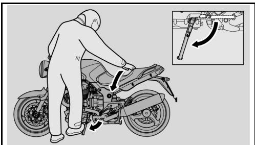
03_10
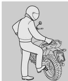
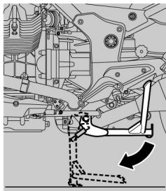
03_11
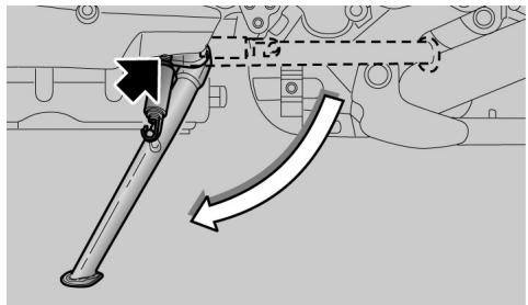
03_12
Soporte (03_10, 03_11, 03_12, 03_13, 03_14)

EL CABALLETE LATERAL Y EL CENTRAL (SI LO HAY) DEBEN GIRAR LIBREMENTE: ENGRASAR LA ARTICULACION SI ES NECESARIO.
CABALLETE LATERAL
En el caso de que alguna maniobra (por exemple: el desplazimiento del vehiculo) haaya provocado el retroceso del caballe,se debe proceder como se indica a continua tion para volver a poner el vehiculo sobre el本身就是:
- Tomar el puno izquierdo y apoyar la mano derecha sobre la parte trase-ra superior del vehiculo.
- Empujar el caballete lateral con el pie decrecho, extendiendo completeness.
- Inclinar el vehiculo hasta que el caballete se apoye en el suejo. Girar el manillar Completely hacía la izquierda
.
ATENCIón
ASEGURARSE DE LA ESTABILIDAD DEL VEHICULO.
Stand (03_10, 03_11, 03_12, 03_13, 03_14)

THE SIDE STAND AND THE CENTRE STAND (IF INSTALLED) MUST MOVE SMOOTHLY; GREASE THE JOINT, IF NECESSARY.
SIDE STAND
If the stand has been folded up for any manoeuvre (for example, when the vehicle is in motion), place the vehicle on the stand again as follows:
- Grasp the left grip and place your right hand on the rear upper part of the vehicle.
- Push on the side stand with your right foot and lower it completely.
- Lean the vehicle until the stand is resting on the ground.
- Turn the handlebar fully to the left.
CAUTION
MAKE SURE THE VEHICLE IS STABLE.
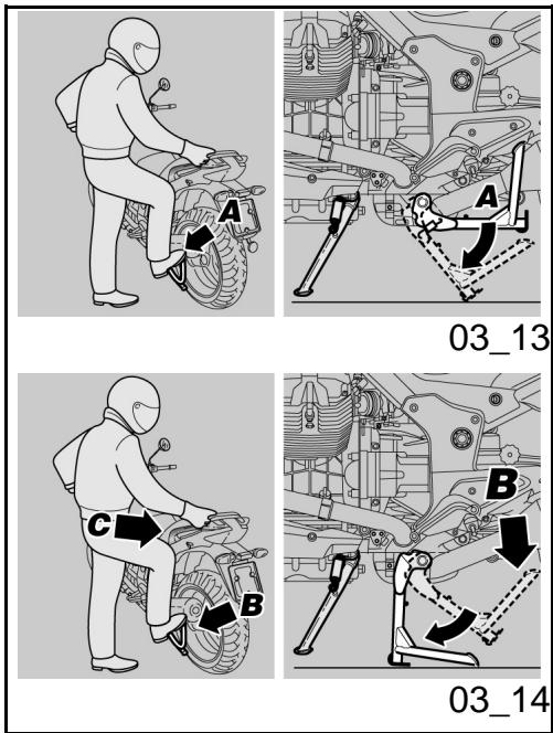
En el caballete lateral se encuesta un interruptor de seguridad que tiene la función de impeder o interruprir el funciona del motor con la marcha acoplada y el caballete lateral bajo.
CABALLETE CENTRAL (DONDE LO HA-YA)
- Tomar el puño izquierdo y el mani-llar.

EMPUJAR EL CABALLETE LATERAL CON EL PIE DERECHO, EXTENDIENDO-LO COMPLETAMENTE, PARA EVITAR LA CAIDA O EL VUELCO DEL VEHICULO EN EL CASO DE QUE EL Mismo PIERDA EL EQUILIBRIO
- Empujar la palianca del caballete central (Pos. A) y apoyarlo al piso.

OPERAR CON CAUTELA.
LA OPERACION DE POSICIONAMIENTO DEL VEHICULO EN EL CABALLETE CENTRAL PUEDE PRESENTAR ALGUNAS DI
A safety switch is installed on the side stand to inhibit ignition or to stop the engine when a gear is engaged and the side stand is lowered.
CENTRE STAND (IF INSTALLED)
- Grasp the left grip and the passenger handgrip.

PUSH DOWN THE SIDE STAND WITH YOUR RIGHT FOOT AND LOWER IT COMPLETELY TO AVOID RISK OF VEHICLE FALLING OR OVERTURNING IN CASE OF LOSS OF BALANCE.
- Push the centre stand lever (Pos. A) and rest it on the ground.

PROCEED WITH CAUTION.
PLACING THE VEHICLE ON ITS STAND
MIGHT BE DIFFICULT SINCE THE
VEHICLE IS VERY HEAVY. RELEASE THE
FICULTADES DEBIDO AL PESO DEL VEHICULO. SOLTAR EL PUÑO Y EL MANILLAR SOLO DESPUÉS DE HABER POSICIONADO EL VEHICULO SOBRE EL CABALLETE.
GRIP AND THE PASSENGER HANDGRIP ONLY AFTER THE VEHICLE IS STEADY ON ITS STAND.
- Cargar el propio peso sobre la palanca (Pos. B) del caballete central y al mesmo tiempo, desplazar el propio centro de gravedad hacía la parte trasera (Pos. C) del vehístico.
-
Retraer el caballete lateral
-
Rest your weight on the lever (Pos. B) of the centre stand and at the same time shift your centre of gravity to the rear part (Pos. C) of the vehicle.
- Fold up the side stand again
Sugerencias contra los robos
ATENCIón
SI SE UTILIZA UN DISPOSITIVO DE BLOQUEO DE DISCO, PRESTAR MUCHA ATENCLON A QUITARLO, ANTES DE CONDICIR EL VEHICULO. LA INOBSERVANCIA DE esta ADVERTENCIA PODRIA CAUSAR SERIOS DANOS A LA INSTALACION DE FRENOS Y PROVOCAR ACCIDENTES CON LOS CONSIGUIENTES DANOS FISICOS O LA MUERTE
Suggestion to prevent theft
CAUTION
WHEN USING A DISC LOCKING DEVICE, PAY UTMOST ATTENTION TO REMOVE IT BEFORE STARTING TO RIDE. FAILURE TO OBSERVE THIS WARNING MAY CAUSE SERIOUS DAMAGE TO THE BRAKING SYSTEM AND ACCIDENTS WITH CONSEQUENT PHYSICAL INJURIES OR EVEN DEATH.
NUNCA dejar la llave de encendido colocada y siempre bloquear el manillar. Aparcar el
NEVER leave the ignition key in the lock and always use the steering lock. Park the
vehiculo en un lugar seguro, en lo possible en un garaje o en un lugar con vigilancia. Siempre que sea possible, utilizar un segundo dispositivo antirrobo. Controlar que los documents y la tasa de circulación estén enorden. Escribir los datos personales y el número de téléphone en esta págrina para poderla identificacion del propietario, en caso de que se encontrar el vehiculo,upones de un robo.
APELLIDO:
NOMBRE:
DIRECCION:
N°
TELEFONICO:
AVVERTENZA
EN MUCHOS CASOS LOS VEHICULOS ROBADOS SE IDENTIFICAN GRACIAS A LOS DATOS INDICADOS EN EL MANUAL DE USO Y MANTENIMIENTO.
vehicle in a safe place such as a garage or a place with guards. Whenever possible, use an additional antitheft device. Make sure all vehicle documents are in order and the road tax paid. Write down your personal details and telephone number on this page to help identifying the owner in case of vehicle retrieval after a theft.
LAST
NAME:
NAME:
ADDRESS:
TELEPHONE
No:
WARNING
IN MANY CASES, STOLEN VEHICLES CAN BE IDENTIFIED THROUGH DATA INDICATED IN THE USE / MAINTENANCE MANUAL
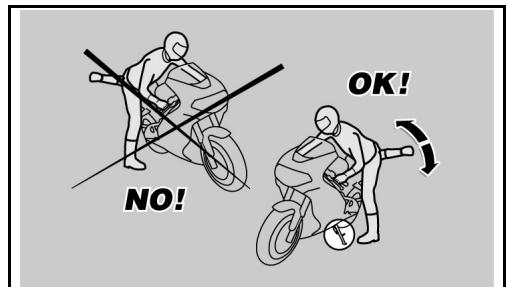
03_15
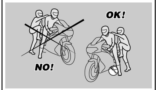
03_16
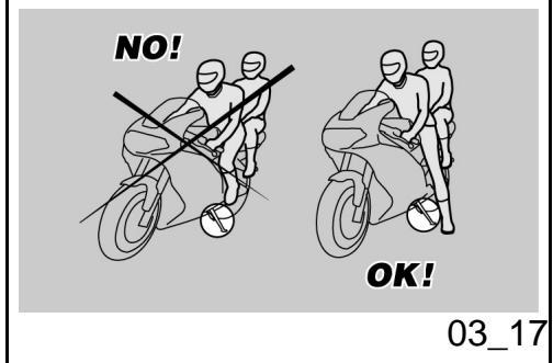
Normas basics de seguridad (03_15, 03_16, 03_17, 03_18, 03_19)
Prestar la maxima atencion a lasindicacionessiguientes porque fueeron redactadas paraevitar daños a laspersonas, a lascasos o alvehiculo,derivados de una possible caida del piloto o del pasajero, o de la caida o vuelco del vehiculo.
Las operaciones de ascenso y descenso del vehiculo deben ser efectuadas con total libertad de movimiento y con las manos libres (de objetos, casco, guantes o antiparras, aun no realizados).
Ascender y descender solo por el lado izquierdo del vehiculo y solo con el caballete lateral bajo.
El caballete fue proyectado para sostener el peso del vehiculo y un minimum de energia, sin conductor ni pasajero.
El ascenso en posicion de conducccion, con el vehiculo posicionado sobre el caballete lateral, solo esta permittedo para prevenir una possible caida o vuelco y no prevé la energia del peso del conductor y/o del pasajero.
Durante el ascenso y el descenso, el peso del vehiculo可以选择 occasional un desbalancemento con la consiguiente perdida de equilibrio y la posibididad de una caía o
Basic safety rules (03_15, 03_16, 03_17, 03_18, 03_19)
Strictly follow the instructions compiled below in order to avoid injury people, damage to property, things and the vehicle in the event the rider or passenger falls off the vehicle and/or the vehicle falls or overturns.
When getting on and off the vehicle, make sure nothing is restricting your movements; you should not be holding any objects in your hands (helmet, gloves or goggles).
Always get on and off the vehicle on the left side and with the side stand lowered.
The stand has been designed to support the weight of the vehicle and a minimum load, without the added weight of rider and passenger.
The purpose of the side stand is to prevent the vehicle from falling or overturning while rider and passenger get on the vehicle and get ready to ride; the stand should not be used to support the weight of rider and passenger.
While getting on and off, the vehicle may become unstable due to its weight and it may
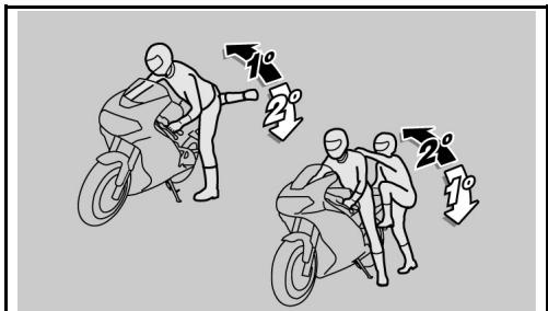
03_18
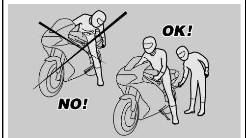
03_19
vuelco.
ATENCIón
EL CONDUCTOR ES SIempre EL PRIMERO QUE ASCIENDE AL VEHICULO Y EL ULTIMO EN DESCENDER Y ES EL QUE GOBIERNA EL EQUILIBRIO Y LA ESTABI-LIDAD DURANTE EL ASCENSO O DESCENSO DEL PASAJERO
Por othera parte, el pasajero debeascender y descender del vehiculo con cautela, para no desbalancear el vehiculo y el conductor.
ATENCLON
ES TAREA DEL CONDUCTOR INSTRUIR AL PASAJERO ACERCA DE LA FORMA CORRECTA DE ASCENDER Y DESCENDER DEL VEHICULO.
PARAFACILITARELASCENSOYELDESCENSODEL PASAJERO,ELVEHICULOESTAPROVISTODELCSCORRESPONDIENTESESTRIBOS.EL PASAJERDEBEUTILIZARSIEMPREELESTRIBOIZQUIERDOPARASCENDERYDESCENDERDELVEHICULO.
NO DESCENDER NI INTENTAR DESCEN- DER DEL VEHICULO SALTANDO O ESTI- RANDO LA PIERNA PARA TOCAR TIE- RRA. EN AMBOS CASOS SE COMPROMETERIA EL EQUILIBRIO Y LA ESTABILIDAD DEL VEHICULO.
fall or overturn.
CAUTION
THE RIDER MUST GET ON THE VEHICLE FIRST AND GET OFF LAST TO BE ABLE TO CONTROL AND BALANCE THE VEHICLE WHILE THE PASSENGER IS GETTING ON OR OFF THE VEHICLE.
When getting on and off the vehicle, the passenger must move carefully so as not to cause a loss of stability for vehicle and rider.
CAUTION
THE RIDER MUST INSTRUCT THE PASSENGER ON HOW TO GET ON AND OFF THE VEHICLE SAFELY.
THE VEHICLE IS EQUIPPED WITH PASSENGER FOOTRESTS TO FACILITATE GETTING ON OR OFF THE VEHICLE. THE PASSENGER MUST ALWAYS USE THE LEFT FOOTREST TO GET ON AND OFF THE VEHICLE.
NEVER GET OFF OR ATTEMPT TO GET OFF THE VEHICLE BY JUMPING OR STRETCHING YOUR LEG TO REACH THE GROUND TO GET OFF THE VEHICLE. THESE ARE INCORRECT PROCEDURES THAT COMPROMISE VEHICLE STABILITY AND BALANCE.
CAUTION
ATENCLON
EL EQUIPJAJE O LAS COSAS FIJADAS A LA PARTE TRASERA DEL VEHICULO PUEDEN CREAR UN OBSTÁCULO EN EL ASCENSO O DESCENSO DEL Mismo.
EN TODOS LOS CASOS PREVER Y EFECTUAR MOVIMIENTOS BIEN CONTROLALDOS CON LA PIERNA DERECHA, LA QUE DEBE EVITAR Y SUPERAR LA PARTE TRASERA DEL VEHICULO (COLA O EQUIPJAJE) SIN DESBALANCEAR EL MISO.
ANY BAGS OR OBJECTS STRAPPED TO THE REAR OF THE VEHICLE CAN REPRESENT AN OBSTACLE WHILE GETTING ON AND OFF.
SWING YOUR RIGHT LEG OVER THE SEAT IN A CONTROLLED MOVEMENT SO AS NOT TO HIT THE REAR PART OF THE VEHICLE (TAIL SECTION OR Luggage) AND COMPROMISE STABILITY.
ASCENSO
- Tomar correctamente el manillar y ascender al vehiculo sin cargar el propio peso en el caballete lateral.
ATENCLON
SI NO LOGRARA APOYAR AMBOS PIES EN EL PISO, APOYAR EL DERECHO (EN EL CASO DE DESBALANCEAMIENTO EL LADO IZQUIERDO ESTÁ "PROTEGIDO" POR EL CABALLET E LATERAL) Y MANTENER EL IZQUIERDO LISTO PARA APOYARSE.
GETTING ON THE VEHICLE
- Grasp the handlebar correctly and get on the vehicle without resting your weight on the side stand.
CAUTION
IF YOU CAN NOT REACH THE GROUND WITH BOTH FEET WHEN SEATED, PLACE YOUR RIGHT FOOT ON THE GROUND (IF YOU LOSE BALANCE, THE SIDE STAND WILL PREVENT A FALL ON THE LEFT SIDE) AND BE READY TO PUT YOUR LEFT FOOT ON THE GROUND.
-
Apoyar también pies en tierra y ende-rezar el vehiculo en posicion de marcha,manteniendolo en equilibrio.
-
Place both feet on the ground, straighten and balance the vehicle keeping it upright.
ATENCLON
EL CONDUCTOR NO DEBE EXTRAER O INTENTAR EXTRAER LOS ESTRIBOS DEL PASAJERO DESDE LA POSICION DE CONDUCCION, PODRIA COMPROMETER EL EQUILIBRIO Y LA ESTABILIDAD DEL VEHICULO.
- Hacer que el pasajero extraiga los dos estribo pasajero. Instruirlo acerca del ascenso al vehiculo. Intervenir con el pie izquierdo en el caballte lateral y hacer que returne Completely.
.
DESCENSO
Elegir la zona de aparecido.
Detener el vehiculo.

CONTROLLER QUE EL TERRENO DE LA ZONA DE APARCAMIENTO ESTÉ LIBRE, SÓLIDO Y PLANO.
- Con el taco del pie izquierdo, accionar en el caballete lateral y extendropletamente.
ATENCIón
CAUTION
THE RIDER MUST NOT EXTRACT OR ATTEMPT TO EXTRACT THE PASSENGER FOOTRESTS WHILE SEATED, BECAUSE THIS MIGHT COMPROMISE VEHICLE STABILITY AND BALANCE.
- Ask passenger to fold out both passenger footrests.
- Instruct passenger on how to get on the vehicle safely.
- Push the side stand with your left foot to fold it up completely.
GETTING OFF THE VEHICLE
- Select a location for parking.
- Stop the vehicle.

MAKE SURE THE GROUND WHERE YOU HAVE PARKED IS FREE, FIRM AND LEVEL.
- With the left shoe heel, lower and extend the side stand completely.
CAUTION
IF YOU CAN NOT REACH THE GROUND
SI NO LOGRARA APOYAR AMBOS PIESEN EL PISO, APOYAR EL DERECHO (ENEL CASO DE DESBALANCEAMIENTO ELLADO IZQUIERDO ESTA "PROTEGIDO"POR EL CABALLET E LATERAL) Y MANTENER EL IZQUIERDO LISTO PARA APOYARSE.
WITH BOTH FEET WHEN SEATED, PLACE YOUR RIGHT FOOT ON THE GROUND (IF YOU LOSE BALANCE, THE SIDE STAND WILL PREVENT A FALL ON THE LEFT SIDE) AND BE READY TO PUT YOUR LEFT FOOT ON THE GROUND.
- Apoyar ambos pies en el piso y mantener en equilibrio el vehiculo en posicion de marcha.
-
Instruir al pasajero acerca de la forma correcta de descender del vehiculo.
-
Place both feet on the ground and balance the vehicle keeping it upright.
- Instruct the passenger on how to get off the vehicle safely.

PELIGRO DE CAIDA O VUELCO.
ASEGURARSE DE QUE EL PASAJERO HAYA DESCENDIDO DEL VEHICULO. NO CARGAR EL PROPIO PESO EN EL CABALLET LATERAL

RISK OF FALLING AND OVERTURNING.
MAKE SURE THE PASSENGER HAS GOT OFF THE VEHICLE.
DO NOT REST YOUR WEIGHT ON THE SIDE STAND.
- Inclinar el vehiculo hasta que el caballete apoye en el piso. Tomar correctamente el manillar y descender del vehiculo.
Girar el manillar completeness la izquierda. -
Hacer que el estribo pasajero returne a su posicion.
-
Lean the vehicle until the stand is resting on the ground.
- Grasp the handlebar firmly and get off the vehicle.
- Turn the handlebar fully to the left.
- Fold up the passenger footrests.

ASEGURARSE DE LA ESTABILIDAD DEL VEHICULO.

MAKE SURE THE VEHICLE IS STABLE.
1200 sport


Cap. 04
Elmantimiento
Chap. 04
Maintenance
Premisa
Normalmente las operaciones de mantenimiento ordinario peuvent ser realizadas por el usuario y a veces peuvent estar contentar de la utilizacion de utilaje especialico y de una cauta preparacion技术水平ica.
En caso de mantenimiento periodico, intervención de asistencia o de consultaística, dirigirse a un Concesionario Oficial Moto Guzzi, que garantizará un service esmerado y<rápido.
AVVERTENZA
ESTE VEHICULO ESTA PREPARADO PARA IDENTIFICAR EN TIEMPO REAL, EVENTUALES ANOMALIAS DE FUNCIONAMIENTO, MEMORIZADAS POR LA CENTRALITA ELECTRONICA.
CADA VEZ QUE EL CONMUTADOR DE ARRANQUE SE POSICIONA EN "ON", EN EL TABLERO SE ENCIENDE, DURANTE APROXIMADAMENTE TRES SEGUNDOS, EL TESTIGO LED "ALARMA".
Foreword
In general terms, scheduled maintenance can be carried out by the owner; however, some operations may require specific tools and technical training.
For regular maintenance, for service support or technical advice, please contact an Official Moto Guzzi dealer who will guarantee accurate and proper service.
WARNING
THIS VEHICLE HAS BEEN PROGRAMMED TO INDICATE IN REAL TIME ANY ACTIVATION FAILURE STORED IN THE ELECTRONIC CONTROL UNIT MEMORY.
ANY TIME THE IGNITION SWITCH IS SET TO "ON", THE "ALARMS" WARNING LIGHT ON THE INSTRUMENT PANEL TURNS ON FOR THREE SECONDS.
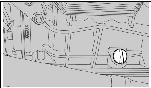
04_01
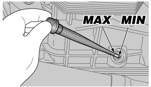
04_02
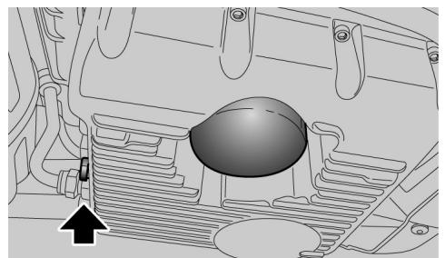
04_03
Comprobacion nivel (04_01, 04_02)
Controlar periodicamente el nivel del aceite del motor y sustituirlo cada 10.000 km (6250 Millas).
Para el control:

EL CONTROL DEL NIVEL DEL ACEITE DEL MOTOR DEBE SER REALIZADO CON EL MOTOR EN CALIENTE Y CON LA VARILLA (1) DESENROSCADA..
SI SE EFFECTUA EL CONTROL DEL NIVEL DEL ACEITE CON EL MOTOR EN FRIO, EL ACEITE PODRIA DESCENDER TEMPORANEAMENTE POR DEBAJO DEL NIVEL "MIN".
LO Dicho NO CONSTITUYE NINGUN PROBLEMA SIempre QUE EN LA PANTALLA NO SE ENCIENDAN EN MODO COMBINADO EL TESTIGO DE ALARMA Y EL ICONO PRESION ACEITE DEL MOTOR.
ATENCLON
PARA CALENTAR EL MOTOR Y LLEVAR EL ACEITE A TEMPERATUREA DE FUNCIONAMIENTO, NO HACER FUNCIONAR EL MOTOR EN RALENTI CON EL VEHICULO DETENIDO.
EL PROCEDIMIENTO CORRECTO PREVÉ
Level check (04_01, 04_02)
Check engine oil level regularly, change it every 10000 km (6250 miles).
To carry out the check:

THE ENGINE OIL LEVEL MUST BE CHECKED WITH A HOT ENGINE AND WITH THE DIPSTICK (1) NOT SCREWED.
IF YOU CHECK LEVEL WHEN THE ENGINE IS COLD, OIL LEVEL COULD TEMPORARILY DROP BELOW THE "MIN" MARK.
THIS SHOULD NOT BE CONSIDERED A PROBLEM PROVIDED THAT THE ALARM WARNING LIGHT AND THE ENGINE OIL PRESSURE ICON DISPLAY DO NOT TURN ON SIMULTANEOUSLY.
CAUTION
DO NOT LET THE ENGINE IDLE WITH THE VEHICLE AT STAND STILL TO WARM UP THE ENGINE AND REACH THE OPERATING TEMPERATURE OF ENGINE OIL.
OIL IS BEST CHECKED AFTER A TRIP OR AFTER TRAVELLING APPROXIMATELY 15 KM (10 MILES) OUT OF TOWN (THIS IS ENOUGH TO HEAT ENGINE OIL TO OPERATING TEMPERATURE).
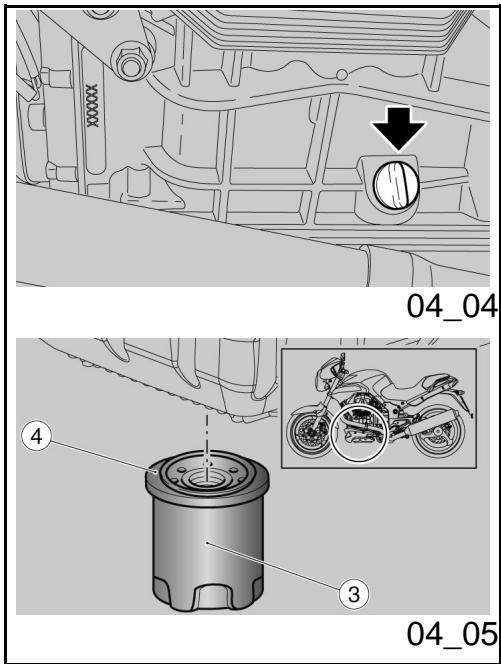
EFFECTUAR EL CONTROL DESPUES DE UN VIAJE O DESPUES DE HABER RECO-RRIDO APROXIMADAMENTE 15 KM (10 MILLAS) FUERA DE LA CIUDAD (SUFICIENTES PARA DAR TEMPERATURA AL ACEITE DEL MOTOR).
Detener el motor.
- Mantener el vehiculo en posicion vertical con las dos ruedas apoyadas en el piso.
Desenroscar el tapón de llenado / varilla;nivel aceite (1).
- Limpiar la varilla nivel aceite (1) e introducirla sin enroscarla.
Extraerla-Newamente y controlar el nivel del aceite.
- El nivel es correcto si alcanza aproximamente el nivel "MAX".
- Stop the engine.
- Keep the vehicle vertical with the two wheels touching the ground.
- Remove the oil filler plug / dipstick (1)
- Clean the oil dipstick (1) and refit without screwing.
- Extract it again and check the oil level.
The level is correct if the oil is just below the "MAX" level mark.
Llenado aceite

NO SOBREPASAR LA MARCA «MAX» NDESCENDER POR DEBAJO DE LA MARCA «MIN», PARA EVITAR GRAVES DANOS AL MOTOR.
Oil top up

DO NOT GO BEYOND THE "MAX" AND BELOW THE "MIN" LEVEL MARK TO AVOID SEVERE ENGINE DAMAGE.
Si es Neededo, restablecer el nivel de
Fill with engine oil as required:
aceite del motor:
Desenroscar y quitar el tapón de llenado (1).

NO AGREGAR ADITIVOS U OTRAS SUSTANCIAS AL ACEITE.
- Unscrew and remove the filler plug (1).

DO NOT ADD ADDITIVES OR OTHER SUBSTANCES TO THE OIL.
Si se usa un embardo u autre objecto, asegurarse de que estéperfectamente limpio.
ATENCIón
UTILIZAR ACEITE DE BUENA CALIDAD, CON GRADUACION 10W - 60.
When using a funnel or any other element, make sure it is perfectly clean.
CAUTION
USE HIGH-QUALITY 10W - 60 OIL.
Llenar restableciendo el nivel solo.
Top up oil until reaching the correct level.
Sustitución aceite (04_03, 04_04, 04_05)
Oil replacement (04_03, 04_04, 04_05)

LAS OPERACIONES PARA LA SUSTITUCION DEL ACEITE DEL MOTOR Y DEL FILTRO DE ACEITE DEL MOTOR PODRIAN RESULTAR DIFICULTOSAS Y COMPLEJAS PARA PERSONAS INEXPERTAS.

CHANGING ENGINE OIL AND ENGINE OIL FILTER CAN PROVE DIFFICULT IF YOUR ARE INEXPERIENCED.
TAKE YOUR VEHICLE TO AN OFFICIAL MOTO GUZZI DEALER IF NECESSARY.
EN CASO DE NECESIDAD, DIRIGIRSE A UN CONCESSIONARIO OFICIAL MOTO GUZZI.
SI DESEA EFFECTUARLO PERSONALMENTE, ATENERSE A LAS SIGUIENTES INSTRUCCIONES.
IF YOU WISH TO PERFORM THESE OPERATIONS YOURSELF, FOLLOW THESE INSTRUCTIONS.
Controlar periodicamente el nivel del aceite del motor y sustituirlo cada 10.000 km (6250 Millas).
Para la sustitución:
ATENCIón
PARALOGRAR UN MEJOR Y COMPLETO VACIADO,ES NECESARIO QUE EL ACEITE ESTE CALIENTE Y POR LO TANTOMASFLUIDO,CONDICIONQUE SE CONSIGUE DESPUES DE CASI VEINTE MINUTOS DE FUNCIONAMENTO NORMAL.

EL MOTOR CALIENTE TIENE ACEITE CON ALTA TEMPERATUREA, EXTREMAR LOS CUIDADOS PARA NO QUEMARSE DURANTE LAS SIGUIENTES OPERACIONES.
- Colocar un recipiente con capacité superior a 4000 cc en correspondencia con el tapón de drenaje
Check engine oil level regularly, change it every 10000 km (6250 miles).
For replacement:
CAUTION
HOT OIL IS MORE FLUID AND WILL DRAIN OUT MORE EASILY AND COMPLETELY; IDEAL TEMPERATURE IS REACHED AFTER THE ENGINE HAS RUN FOR ABOUT TWENTY MINUTES.

OIL BECOMES VERY HOT WHEN THE ENGINE IS HOT; BE CAREFUL NOT TO GET BURNED WHEN CARRYING OUT THE OPERATIONS DESCRIBED BELOW.
- Place a container with a capacity of more than 4000~cm^3 under the drain plug (1).
(1).
Desenroscar y sacar el tapón de drenaje (1).
Desenroscar y quitar el tapón de llenado (2).
- Descargar y partir gotear durante uno horas el aceite bajo el recipient.
- Controller y, eventualmente, sustituir las arandelas de estanqueidad del tapón de drenaje (1).
- Quitar los residuos metálicos que se queden pegados al imán del tapón de drenaje (1).
- Enroscar y aparear el tapón de drenaje (1).
Par de apriete tapones de drenaje (1): 12 Nm (1,2 kgm).
- Unscrew and remove the drain plug
(1)
. - Unscrew and remove the filler plug (2).
- Drain the oil into the container; allow several minutes for the oil to drain out completely.
- Check the sealing washers of the drain plug (1) and replace them, if necessary.
- Remove any metal scrap attached to the drain plug (1) magnet.
- Screw in and tighten the drain plug (1).
Tightening torque for drain plugs (1): 12 Nm (1.2 kgm).
SUSTITUCION DEL FILTRO DE ACEITE MOTOR
ENGINE OIL FILTER REPLACEMENT
Sustituir el filtro de aceite motor cada 10.000km (6250 millas) (o en cada sustitución del aceite del motor).
- Quitar el filtro de aceite motor (3) desenroscándolo de su alojamento.
Change the engine oil filter every 10000 km (6250 miles) (or each time you change the engine oil).
- Unscrew the engine oil filter (3) from its seat.

NO VOLVER A UTILIZAR EL FILTRO USA

NEVER REUSE A FILTER.
DO.
-
Tender una capa de aceite en el anillo de estanqueidad (4) del nuevo filtro de aceite motor.
Montar y enroscar el nuevo filtro en el alojamento, ajustandolo a mano. -
Spread a thin layer of oil on the sealing ring (4) of the new engine oil filter.
- Fit the new filter in the seat and screw it manually.
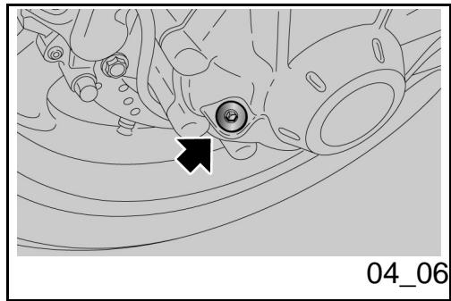
Nivel aceite cardán (04_06)
Controlar periodicamente el nivel de aceite del cardan y sustituirlo afterwards de los primeros 1.000km (625 millas) y bajo cada 20.000km (12500 millas).
Para el control:
- Mantener el vehístico en posición vertical con las dos ruedas apoyadas en el piso.
Desenroscar y quitar el tapón de nivel. - Controlar que el aceite roce el orifico del tapón de nivel. Si el aceite está por debajo del nivel indicado se debe proceder al llenado.
Para llenar y eventualmente sustituir el aceite del grupo transmisión cardánica, dirigirse a un Concesionario Oficial Moto Guzzi.
Universal joint oil level (04_06)
Check cardan shaft oil level regularly; change the oil after the first 1000 km (625 miles) and then every 20000 km (12500 miles).
To carry out the check:
- Keep the vehicle vertical with the two wheels touching the ground.
- Unscrew and remove the level plug.
- Check that oil level is on the rim of the hole of the level plug. Top-up if oil is below the specified level.
To top-up or change the oil in the cardan shaft transmission unit, contact an Official Moto Guzzi Dealer.
Nivel aceite cambio
- Para el control, el llenado y la sustitución del aceite del cambio, dirigir-se a un Concesionario Oficial Moto Guzzi.
Gearbox oil level
- To check, top-up and change gearbox oil, contact an Official Moto Guzzi Dealer.
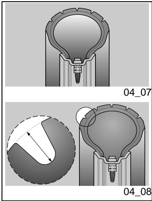
Neumáticos (04_07, 04_08) NEUMÁTICOS
Este vehiculo posee neumáticos sin cámara de aire (tubeless).
ATENCLON
CONTROLAR PERIODICAMENTE LA PRESION DE INFLADO DE LOS NEUMÁTICOS A TEMPERATURA AMBIENTE. SI LOS NEUMÁTICOS ESTAN CALIENTES, LA MEDICION NO SERA CORRECTA. REALIZAR LA MEDICION ESPECIALMENTE ANTES Y DESPUÉS DE UN VIAJE LARGO. SI LA PRESION DE INFLADO ES DEMASIADO ALTA, LAS ASPEREZAS DEL TERRENO NO SE AMORTIGUARAN Y POR LOTANTO SE TRANSMITIRAN AL MANILLAR COMPROMETIENDO DE ESTA MANERA EL CONFORT EN LA MARCHA Y REDUCIENDO TÁMBIEN EL AGARRE A LA CARREtera EN LAS CURVAS.
EN CAMBIO, SI LA PRESION DE INFLADO ES INSUFICIENTE, LOS FLANCOS DE LOS NEUMÁTICOS TRABAJARÁN DEMA
Tyres (04_07, 04_08) TYRES
This vehicle is fitted with tyres without inner tubes (tubeless).
CAUTION
CHECK TYRE INFLATION PRESSURE REGULARLY AT AMBIENT TEMPERATURE. THE MEASUREMENT MAY BE INCORRECT IF TYRES ARE WARM. CHECK TYRE PRESSURE PARTICULARLY BEFORE AND AFTER A LONG JOURNEY. IF TYRE PRESSURE IS TOO HIGH, THE SURFACE UNEVENNESS IS NOT CUSHIONED AND IS SENT TO THE HANDLE-BAR, RESULTING IN UNPLEASANT RIDING AND POOR ROAD GRIP SPECIALLY WHEN TURNING.
CONVERSELY, WITH LOW TYRE PRESSURE, TYRE SIDEWALLS BEAR MORE STRESS AND THE TYRE CAN SLIDE ON THE RIM OR EVEN GET DETACHED RESULTING IN LOSS OF CONTROL OVER THE VEHICLE.
SIADO Y PODRIA PRODUCIRSE UN DESPLAZAMIENTO DE LA GOMA SOBRE LA LLANTA, O BIEN SU SEPARACION, CON LA CONSIGUIENTE PERDIDA DE CONTROL DEL VEHICULO.
EN CASO DE FRENADAS BRUSCAS, LOS NEUMÁTICOS PODRIAN SALIRSE DE LAS LLANTAS.
Y POR ÚLTIMO, EL VEHÍCULO PODRÍA DERRAPAR EN CURVAS.
CONTROLLER EL ESTADO SUPERFICIAL Y EL DESGASTE, YA QUE UN ESTADO DEFICIENTE DE LOS NEUMÁTICOS COMPROMETERIA LA ADHERENCIA EN LA CARREtera Y LA MANIOCRABILIDAD DEL VEHÍCULO.
ALGUNOS TIPOS DE NEUMÁTICOS, HOMOLOGADOS PARA ESTE VEHÍCULO, POSEEN INDICadores DE DESGASTE.
EXISTEN VARIOS TIPOS DE INDICADORES DE DESGASTE. INFORMARSE CONEL PROPIO REVENDEDOR ACERCA DELAS MODALIDADES DE CONTROL DESGASTE.
CONTROLLER VISUALMENTE EL CONSUMO DE LOS NEUMÁTICOS, SI ESTÁN DESGASTADOS, SUSTITUIRLOS.
SI LOS NEUMÁTICOS ESTÁN VIEJOS, AUNQUE NO COMPLETAMENTE DESGASTADOS, PUEDEN ENDURECERSE Y NO GARANTIZAR LA ADHERENCIA EN CARREtera. EN Este CASO SUSTI-
IN CASE OF SHARP BRAKING, TYRES CAN EVEN GET OFF THE RIMS.
EVENTUALLY WHEN TURNING, THE VEHICLE MAY SWERVE.
CHECK TYRE TREAD FOR WEAR AS INADEQUATE CONDITIONS CAN RESULT IN LACK OF GRIP AND POOR MANOEUVRABILITY.
SOME TYRE TYPES HOMOLOGATED FOR THIS VEHICLE FEATURE WEAR INDICATORS.
THERE ARE DIFFERENT TYPES OF WEAR INDICATORS. CONSULT YOUR DEALER ON METHODS TO CHECK FOR WEAR.
CARRY OUT A VISUAL INSPECTION FOR TYRE WEAR AND TEAR, REPLACE THEM IF WORN.
WHEN TYRES ARE OLD, THE MATERIAL MAY HARDEN AND NOT PROVIDE ADEQUATE GRIP, EVEN IF TYRES ARE STILL WITHIN THE WEAR LIMIT. REPLACE TYRES IF THIS OCCURS. REPLACE A TYRE WHEN WORN OR IF TREAD HAS A PUNCTURE BIGGER THAN 5 MM.
AFTER A TYRE IS MENDED, BALANCE THE WHEELS.
USE ONLY TYRE SIZES INDICATED BY THE MANUFACTURER. DO NOT FIT TYRES WITH INNER TUBES ON RIMS
TUIROS. SUSTITUIR EL NEUMÁTICO SI ESTÁ DESGASTADO O SI SE EVIDENCIÀ UNA PERFORACION MAYOR DE 5 MM. EN LA ZONA DE LA BANDA DE RODADURA.
DESPUÉS DE REPARAR UN NEUMÁTICO, SE DEBE PROCER AL EQUILIBRADO DE LAS RUEDAS.
USARTOS CON NEXUSAMIENTE NEUMÁTICOS CON LAS DIMENSIONES INDICADAS POR LA EMPRESA. NO INSTALAR NEUMÁTICOS DEL TIPO CON CÁMARA DE AIRE EN LLANTAS PARA NEUMÁTICOS TUBELESS Y VICEVERSA. CONTROLAR QUE LAS VALVULAS DE INFLADO POSEAN LAS TAPAS PARA EVITAR LA PÉRDIDA DE PRESION DE LOS NEUMÁTICOS.
LAS OPERACIONES DE SUSTITUCION, REPARACIOn, MANTENIMIENTO Y EQUILIBRADO SON MUY IMPORTANTES: PA- RA REALIZARLAS SE DEBE CONTAR CON LAS HERRAMIENTAS ADECUADAS Y CON LA EXPERIENCIA NECESARIA. POR Este MOTIVO SE RECOMIENDA DIRIGIRSE A UN CONCESSIONARIO OFICIAL O A UN TALLER DE NEUMATICOS ESPECIALIZADO PARA EJECUTAR LAS OPERACIONES ANTERIORES.
SI LOS NEUMÁTICOS SON NUEVOS, PUEDEN ESTAR RECUBIERTOS POR UNA CAPA RESBALADIZA: CONDU CIR CON CAUTELA DURANTE LOS PRIME
FOR TUBELESS TYRES OR VICE VERSA. CHECK THAT THE INFLATION VALVES HAVE THEIR CAPS TO AVOID UNEXPECTED FLAT TYRES.
REPLACEMENT, REPAIR, MAINTENANCE AND BALANCING OPERATIONS ARE HIGHLY IMPORTANT AND SO THEY SHOULD BE CARRYING OUT USING THE SPECIFIC AND WITH THE ADEQUATE KNOWLEDGE. HAVE YOUR TYRES AND WHEELS SERVICED AT AN OFFICIAL DEALER OR A SPECIALISED TYRE REPAIRER.
NEW TYRES MAY BE COATED WITH AN OILY FILM: RIDE WITH CAUTION DURING THE FIRST KILOMETRES. DO NOT APPLY UNSUITABLE LIQUIDS ON TYRES.
WHEN TYRES ARE OLD, THE MATERIAL MAY HARDEN AND NOT PROVIDE ADEQUATE GRIP, EVEN IF TYRES ARE STILL WITHIN THE WEAR LIMIT. TYRE GRIP.
IF THIS IS THE CASE, REPLACE THE TYRES.
ROS KILOMETROS. NO APLICAR NINGUN LIQUIDO INADECUADO A LOS NEUMATICOS.
SI LOS NEUMÁTICOS ESTÁN VIEJOS, AUNQUE NO COMPLETAMENTE DESGASTADOS, PUEDEN ENDURECERSE Y NO GARANTIZAR. LA ADHERENCIÀ EN CARREtera.
EN ESTE CASO, SUSTITUIR LOS NEUMÁTICOS.
Limineto de profundidad de la banda derodadura:
delantera y trasera 2 mm. (USA 3 mm) y en todos los casos no inferior a lo prescrito por la legislacion vigente en el País de'utilisation del vehiculo.
Minimum tread depth:
front and rear 2 mm (USA 3 mm) and anyway not less than required by the regulations in force in the country where the vehicle is used.
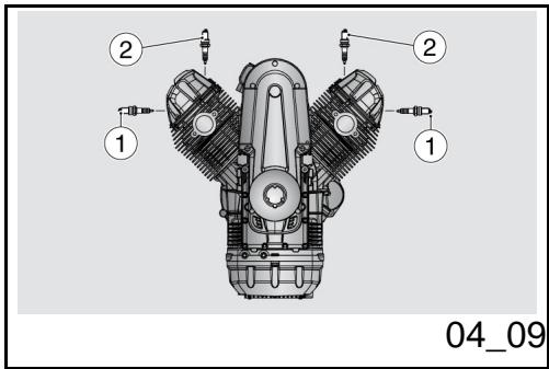
Desmontaje bujía (04_09, 04_10, 04_11, 04_12, 04_13)

LAS SIGUIENTES INSTRUCCIONSE SREFIEREN UNICAMENTE A LAS BUJIAS EXTERNAS (1). LA VERSION 1100 CONSTA TAMIEN DE DOS BUJIAS INTERNNAS (2), PARA CUYA SUSTITUCION DIRIGIRSE A UN TALLER AUTORIZADO MOTO
Spark plug dismantlement (04_09, 04_10, 04_11, 04_12, 04_13)

THE FOLLOWING INSTRUCTIONS APPLY ONLY TO OUTER SPARK PLUGS (1). THE 1100 VERSION ALSO HAS TWO INNER SPARK PLUGS (2); CONTACT AN OFFICIAL MOTO GUZZI DEALER TO HAVE
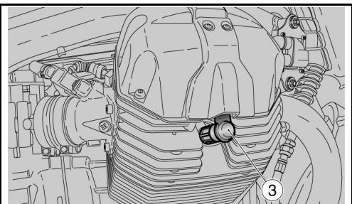
04_10
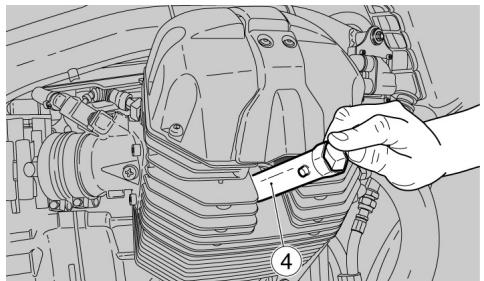
04_11
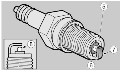
04_12
GUZZI.

SUSTITUIR SIEMPRE AMBAS BUJIAS EXTERNAS (1) INCLUSO SI UNA SOLA DEELLAS REQUIERE SER SUSTITUIDA.
Para extraerla:
- Quitar la pipeta (3) de la bujía.
- Eliminar toda suciedad de la base de la bujía.
- Introducir en la bujía la llave suministrada en dotación con el kit de herramrientas.
- Introducir en el alojamiento hexagonal de la llave para la bujía, la llave (4) suministrada en dotación con el kit de herramrientas.
Desenroscar la bujía y extraerla de su alojamento, prestando atencion a que no ingrese polvo u otheras sustancias en el cilindro.
Para el control y la limpieza:

PARA LA LIMPIEZA NO UTILIZAR CEPILLOS METÁLICOS Y/O PRODUCTOS ABRASIVOS, SINO EXCLUSIVAMENTE UN CHORRO DE AGUA A PRESión.
THEM REPLACED.

ALWAYS REPLACE BOTH OUTER SPARK PLUGS (1), EVEN IF ONLY ONE NEEDS REPLACING.
For removal:
- Remove the spark plug tube (3).
- Remove any trace of dirt from the spark plug base.
- Fit the special spanner supplied in the tool kit to the spark plug.
- Insert the key (4) supplied in the tool kit into the hexagonal head of the spark plug spanner.
- Unscrew the spark plug and remove it from its seat, making sure no dust or dirt falls into the cylinder.
Checking and cleaning:

TO CLEAN THE SPARK PLUGS,DO NOT USE METAL BRUSHES AND/OR ABRASIVEPRODUCTS;ONLYACOMPRESSSED AIRJET.
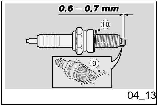
Leyenda:
- electrodo central (5);
-aislante (6); - electrodo lateral (7).
- Contralar que los electrodos y el aislante de la bujía no presenten depósitos de carbono o MARCAS de corrosión, si fuera NEEDario limpar con unchorro de agua a presión.
LaBJIaBeSusituiduCuando presenta: grieras en elaislante,electrodos corroidos, depotos excessivos o electrodo central (5) con la cabeza redondeada (8).
- Controlar la distancia entre los electrodos con un calibre de espaces del tipo con hilo (9).
ATENCIón

NO INTENTAR DE NINGUNA MANERA RESTABLECER LA DISTANCIA ENTRE LOS ELECTRODOS.
La distancia entre los electrodos debe ser de 0,6 - 0,7 mm. (0.023 - 0.027 pulgadas): si fuera diferente, sustituir la bujía.
- Asegürese del buen estado de la arandela (10).
Key:
- central electrode (5);
- insulator (6);
-
side electrode (7);
-
Check that the electrodes and insulator of spark plug do not show traces of carbon deposits and of corrosion. If required, clean them using a compressed air jet.
Replace the spark plug if its insulator is cracked, the electrodes show signs of corrosion or excessive deposits or the top (8) of the central electrode (5) gets rounded.
- Check the electrode gap with a feeler thickness gauge (9).
CAUTION

DO NOT ATTEMPT TO READJUST THE ELECTRODE GAP.
The electrode gap should be between 0.6 - 0.7 mm (0.023 - 0.027 in). Replace the spark plug if the gap is different.
Make sure that the washer (10) is in good conditions.
Para la instalación:
- Con la arandela (10) montada, enroscar a mano la bujía para evaporar que se dañe la rosca.
- Apretar con la llave suministrada en dotación con el kit de herramrientas, hacer que cada bucía realice 1/2 giro para comprimir la arandela.
Par de apriete bujía: 20 Nm (2 kgm).
LA BUJIA DEBE ESTAR BIEN ENROSCADA, DE OTRA MANERA EL MOTOR PODRIA SOBRECALENTARSE Y DANARSE GRAVEMENTE.
USAR SOLAMENTE BUJIAS DEL TIPO RECOMENDADO; EN CASO CONTRARIOSE PODRIAN COMPROMETER LAS PRESTACIONES Y LA DURACION DEL MOTOR.
- Introducir correctamente la pipeta de la bujía, de manière que no se suele con las vibraciones del motor.
Installation:
- Fit the washer (10) and then screw the spark plug manually to avoid damaging the thread.
- Tighten using the spanner supplied with the toolkit, turning each spark plug by 1/2 turn to compress the washer.
Spark plug tightening torque: 20 Nm (2 kgm).
TIGHTEN THE SPARK PLUG CORRECTLY, OTHERWISE THE ENGINE MAY OVERHEAT AND GET IRRETRIEVABLE DAMAGED.
USE ONLY THE RECOMMENDED TYPE OF SPARK PLUG, OTHERWISE, THE ENGINE DURATION AND PERFORMANCE COULD BE COMPROMISED.
- Place the spark plug tube correctly so that it does not get detached due to engine vibrations.
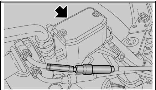
04_14
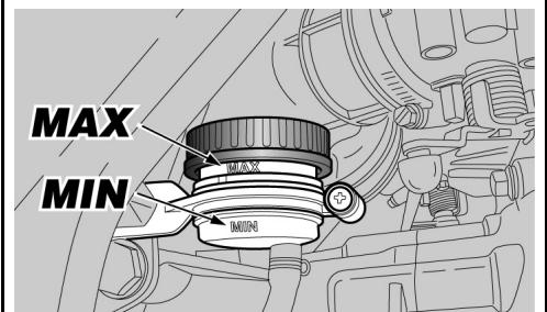
04_15
Control nivel aceite frenos (04_14, 04_15)
Control liquido de los frenos
- Posicionar el vehiculo sobre el caballe.
- Para el freno delantero, girar el manillar Completely hacer la derecha.
- Para el freno trasero,mantener el vehiculo en posicion vertical de manera que el liquido contenido en el deposito se incluye paralelo a la tapa.
- Controlar que el liquido contenido en el deposito supere la referencia "MIN":
MIN = nivel minimo.
M = n ivel maximo.
Si el liquido no llega por lo menos a la hora «MÍN»:
- Controller el desgaste de las pastillas de frenos, y del disco.
Si las pastillas y/o el disco no necessitan ser sustituidos, proceder al llenado.
In caso de tener que sustituir las pastillas y/o el disco controlar el liquido de los frenos y eventualmente efectuar el llenado.
Checking the brake oil level (04_14, 04_15)
Brake fluid check
- Place the vehicle on its stand.
For the front brake, turn the handlebar fully to the right. - For the rear brake, keep the vehicle upright so as the fluid in the reservoir is at the same level with the plug.
Make sure that the fluid in the reservoir is above the "MIN" mark.
MIN = minimum level
MAX = maximum level
If the fluid does not reach at least the "MIN" reference mark:
- Check brake pads and disc for wear.
If the pads and/or the disc do not need replacing, top up the fluid.
If the pads and/or the disc are replaced, check the brake fluid and top up if necessary.
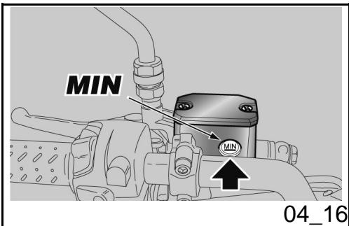
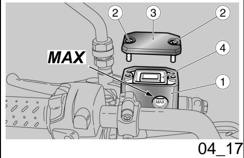
Control liquido embrague (04_16)
- Posicionar el vehiculo en el caballete.
Girar el manillar parcialmente hacer la referencia de manos tal que el liquido contenido en el depuesto del liquido del embarque se incluye paralelo al borde del depuesto del liquido del embarque. - Controlar que el liquido contenido en el deposito supere la referencia "MIN"
MIN = nivel minimo.
M = n ivel maximo.
Si el liquido no alcanza por lo menos la referencia "MIn", proceder al llenado.
Reposicion liquido embrague (04_17)
- Colocar correctamente la junta (4) en su alojamento.
- Colocar la tapsa (3).
- Enroscar y aparear los tornillos (2).

DURANTE EL LLENADO NO SUPERAR EL NIVEL "MAX".
Checking clutch fluid (04_16)
- Place the vehicle on its stand.
- Turn the handlebar partially to the right, so that the fluid inside the clutch fluid reservoir is parallel to the reservoir edge.
Make sure the fluid level is above the "MIN" mark.
MIN = minimum level
MAX = maximum level
Top up if the fluid does not reach at least the "MIN" reference mark.
Topping up clutch fluid (04_17)
- Refit the gasket (4) correctly in its seat.
- Refit the cover (3).
- Screw and tighten the screws (2).

DO NOT EXCEED THE "MAX" LEVEL MARK WHEN TOPPING UP.
CONTROLLER EL BUEN FUNCIONAMIENTO DEL EMBRAGE.
SI LA PALANCA DE MANDO DEL EMBRAGUE REALIZARA UNA CARRERA EXCESIVA EN VACIO O EN EL CASO DE UNA PÉRDIDA DE EFICIENCY EN LA INSTALLACION DEL EMBRAGUE, DIRIGIRSE A UN CONCESSIONARIO OFICIAL MOTO GUZZI, DADO QUE PODRIA SER NECESARIO EFFECTUAR LA PURGA DEL AIRE DE LA INSTALACION.
CHECK THE CLUTCH FOR PROPER OPERATION.
IF CLUTCH LEVER EMPTY TRAVEL IS TOO LONG OR IN THE EVENT OF CLUTCH INEFFICIENCY, CONTACT AN OFFICIAL MOTO GUZZI DEALER,AS THE SYSTEM MAY NEED BLEEDING.
-
Utilizando un destornillador en cruz desenroscar los dos tornillos (2) del deposito liquido del embarque (1).
Levantar y quitar la tapa (3) con los tornillos (2).
Extraer la junta (4). -
Unscrew the two screws (2) of the clutch fluid reservoir (1) using a crosshead screwdriver.
- Lift and remove the cover (3) and also the screws (2).
- Remove the gasket (4).
Llenar el deposito con el liquido del embar-
gue hasta cubrir completeness el visor que
corresponde al nivel máximo.

PARA EVITAR DERRAMAR EL LIQUIDO DURANTE EL LLENADO, SE RECOMIENDA MANTENER EL LIQUIDO EN EL DEPOSITO PARALELO AL BORDE DEL DEPOSITO (EN POSICION HORIZONTAL).
NO AGREGAR ADITIVOS U OTRAS SUS
Top up the reservoir with clutch oil until fluid completely covers sight glass corresponding to the maximum level.

TO AVOID SPILLING FLUID WHILE TOPPING-UP, KEEP THE TANK PARALLEL TO THE RESERVOIR EDGE (IN HORIZONTAL POSITION).
DO NOT ADD ADDITIVES OR OTHER SUBSTANCES TO THE LIQUID.
TANCIAS AL LIQUIDO.
SI SE USA UN EMBUDO U OTRO OBJECTO, ASEGURARSE DE QUE ESTÉ PERFECTAMENTE LIMPIO.

PELIGRO DE DERRAME DEL LÍQUIDO DEL EMBRAGUE. NO ACCIONAR LA PALANCA DEL EMBRAGUE SI EL TAPON DEL DEPOSITO DEL LÍQUIDO ESTA FLOJO O FALTARA.
COLOCAR UN PANO DEBAJO DEL DEPOSITO DEL LIQUIDO DEL EMBRAGUE COMO MEDIDA PREVENTIVA POR EVENTUALES PÉRDIDAS DEL LIQUIDO.

EVITAR LA EXPOSICION PROLONGADA AL AIRE DEL LIQUIDO MANDO EMBRAQUE.
EL LIQUIDO DEL EMBRAGUE ES HIGROSCOPICO Y EN CONTACTO CON EL AIRE ABSORBE LA HUMEDAD.
EL DEPOSITO DEL LIQUIDO MANDO EMBRAGUE DEBE PERMANECER ABIERTOSOLO EL TIEMPO NECESARIO PARA EFFECTUAR EL LLENADO.
WHEN USING A FUNNEL OR ANY OTHER ELEMENT, MAKE SURE IT IS PERFECTLY CLEAN.

RISK OF CLUTCH FLUID SPILLAGE. DO NOT OPERATE THE CLUTCH LEVER WITH FUEL RESERVOIR CAP LOOSEND OR REMOVED.
PLACE A CLOTH UNDER THE CLUTCH RESERVOIR TO PROTECT IT FROM ANY FLUID SPILLAGE.

AVOID PROLONGED AIR EXPOSURE OF THE CLUTCH CONTROL FLUID.
THE CLUTCH FLUID IS HYGROSCOPIC AND ABSORBS MOISTURE WHEN IN CONTACT WITH AIR.
LEAVE THE CLUTCH CONTROL FLUID RESERVOIR OPEN ONLY FOR THE TIME NEEDED TO COMPLETE THE TOPPING UP PROCEDURE.
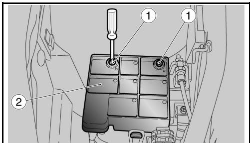
04_18
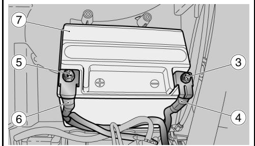
04_19
Puesta en servicios de una baterianea (04_18, 04_19)
- Asegurar de que el conmutador de encendido se enquiryra en "OFF".
- Quitar el asiento del piloto.
Desenroscar los dos tornillos (1) y desplazar la taps (2).
Desenroscar y qutar el tornillo (3) del borne negativo (-). - Desplazar lateralmente el cable negativo (4).
Desenroscar y qutar el tornillo (5) del borne positivo (+). - Desplazar lateralmente el cable positivo (6).
- Tomar con fuerza la batería (7) y sacarla de su alojamento levantándola.
- Colocar la bateria sobre una superficie plana, en un lugar fresco y seco.
- Volver a colocar el asiento del piloto.
Para instalar una nuevo bateria ejectar las operaciones descritas en sentido inverso.
ATENCLON
PARAVOLVERAMONTARLA,PRIMERO SEDEBECONECTARELCABLEENEL BORNEPOSITIVO (+) YLUEGOELDEL
Use of a new battery (04_18, 04_19)
Make sure the ignition switch is set to "OFF".
- Remove the rider saddle.
- Unscrew the two screws (1) and remove the cover (2).
- Loosen and remove the screw (3) of the negative terminal (-).
- Move the negative leads (4) aside.
- Loosen and remove the screws (5) of the positive terminal (+).
- Move the positive leads (6) aside.
- Hold the battery (7) firmly and lift it out of its compartment.
- Put the battery away on a level surface, in a cool and dry place.
- Refit the rider seat.
To install a new battery follow the operations described above but in reverse order.
CAUTION
WHEN REFITTING, FIRST CONNECT THE LEAD TO THE POSITIVE TERMINAL (+) AND AFTERWARDS THE LEAD TO THE NEGATIVE TERMINAL (-) .

CHECK THAT THE BATTERY LEADS AND TERMINALS ARE:
- IN GOOD CONDITION (NOT CORRODED
BORNE NEGATIVO (-).

CONTROLLER QUE LOS TERMINALES DE LOS CABLES Y LOS BORNES DE LA BATERIA SE ENCIENTREN:
EN BUENAS CONDICIONES (Y NO CORROÍDOS O CUBIERTOS DE DEPOSITO);
- CUBIERTOS CON GRASA NEUTRA O CON VASELINA.
Comprobacion del nivel del electrolito
AVVERTENZA
ESTE VEHICULO ESTA EQUIPADO CON UNA BATERIA QUE NO REQUIRE MANTENIMIENTO Y NO REQUIRE NINGUN TIPO DE INTERVENTION, SINO UN ESPORÁDICO CONTROL Y UNA EVENTUAL RECARGA.
OR COVERED BY DEPOSITS);
- COVERED BY NEUTRAL GREASE OR PETROLEUM JELLY.
Checking the electrolyte level
WARNING
THIS VEHICLE IS FITTED WITH A MAIN- TENANCE-FREE BATTERY AND DOES NOT NEED ANY INTERVENTION, EXCEPT FOR SPORADIC CHECKS AND RE- CHARGE.
Recarga bateria
Sacar la batería.
- Preparar un cargador de bateria inadeado.
- Predisponer el cargador de bateria para el tipo de recarga indicada
- Conectarla al cargador de bateria.
Charging the battery
- Remove the battery.
Get an adequate battery charger. - Set the battery charger for the recharge type indicated.
- Connect the battery to the battery charger.
DURANTE LA RECARGA O USO, VENTILAR ADECUADAMENTE EL LOCAL, EVITAR LA INHALACION DE LOS GASES EMITIDOS DURANTE LA RECARGA.
WHEN RECHARGING OR USING THE BATTERY, BE CAREFUL TO HAVE THE ROOM ADEQUATELY AIRED. DO NOT BREATH GASES RELEASED WHEN THE BATTERY IS RECHARGING.
Encender el cargador de baterías.
Switch on the battery charger.
\section*{Characteristicas Técnicas}
Characteristic
MODALIDAD DE RECARGA
RECHARGE MODES:
Recarga - Normal
Recharge - Ordinary
Corrente Eléctrica - 1,8 A
Electric Current - 1.8A
Tiempo - 8-10 horas
Time - 8-10 hours
Larga inactividad
Long periods of inactivity


SI EL VEHICULO PERMANECE INACTIVO DURANTE MÁS DE VEINTE DIÁS, DESCONECTAR LOS FUSIBLES DE 30 A PARA EVITAR LA DEGRADACION DE LA BATERIA DEBIDA AL CONSUMO DE CORRIENTE DEL ORDENADOR MULTIFUNCIÑ.
IF THE VEHICLE IS INACTIVE LONGER THAN TWENTY DAYS, DISCONNECT THE 30 A FUSE, TO AVOID BATTERY DETERIORATION DUE TO CURRENT CONSUMPTION BY THE MULTIFUNCTION COMPUTER.
ATENCIón
CAUTION
EXTRAER LOS FUSIBLES DE 30A IMPLICA PONER A CERO LAS FUNCTIONS: RELOJ DIGITAL, INFORMACIONES DE
REMOVING THE 30 A FUSES RESETS THESE FUNCTIONS: DIGITAL CLOCK, TRIP INFORMATION AND CHRONOMETRICAL TIMES.
VIAJE Y MEDICIONES CRONOMÉTRICAS.
En caso de que el vehiculo permanezca inactivo durante mas de quince días es necesario recargar la batería paraatar la sulfatacion.
Extraer la bateria.
En los periodos invernales o cuando el vehiculo permanece detenido, controlar periodically la energia (una vez al mes), para evitar su degradacion.
Recargarla completeness con una carga normal.
Si la batería permanece en el vehúculo, desconectar los cables de los bornes.
If the vehicle is inactive longer than fifteen days, it is necessary to recharge the battery to avoid sulphation.
- Remove the battery.
In winter or when the vehicle remains stopped, check the charge frequently (about once a month) to avoid deterioration.
- Recharge it fully with an ordinary charge.
If the battery is still on the vehicle, disconnect the cables from the terminals.
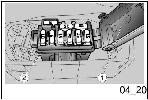
Fusibles (04_20, 04_21, 04_22, 04_23, 04_24, 04_25, 04_26)
NO REPARAR FUSIBLES DEFECTUOSOS.
NUNCA UTILIZAR FUSIBLES DIFERENTES A LOS ESPECIFICADOS.
PODRIA CAUSAR DANOS AL SISTEMA ELECTRICO E INCLUSO UN INCENDIO EN CASO DE CORTOCIRCUito.
Fuses (04_20, 04_21, 04_22, 04_23, 04_24, 04_25, 04_26)
DO NOT REPAIR FAULTY FUSES.
NEVER USE FUSES OTHER THAN THE ONES SPECIFIED.
DAMAGE TO THE ELECTRICAL SYSTEM OR EVEN FIRE MAY BE CAUSED IN CASE OF A SHORT CIRCUIT.
NOTE
IF A FUSE BLOWS OUT FREQUENTLY,
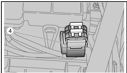
04_21
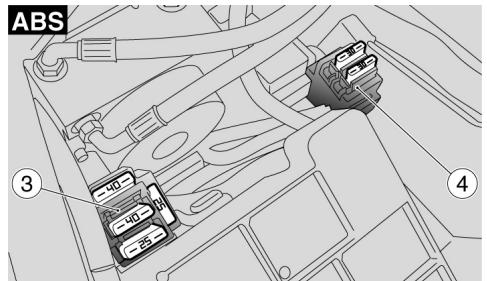
04_22
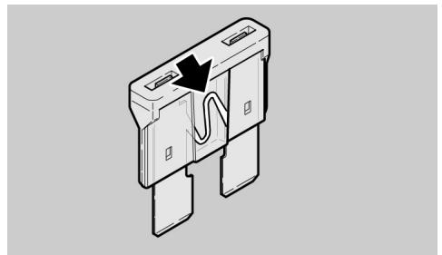
04_23
NOTA
CUANDO UN FUSIBLE SE DANA FRECUENTEMENTE, ES PROBABLE QUE EXISTA UN CORTOCIRCUito O UNA SOBRECARGA. EN ESTE CASO CONSULTAR A UN CONCESIONARIO OFICIAL GUZZI.
Si se detecta que un componente électrique no funciona o funciona en forma anomal, o no se produce el arranque del motor, esnecessary controlar los fusibles.
Primero controlar los fusibles secundarias(2),los fusibles delsystema ABS (3) (donde esteprevisto)y a continuacion los fusibles principales (4).
Para el control:
- Posicionar en 'OFF' el conmutador de arranque, para evaporar un cortocircuito accidental.
- Sacar el asiento del conductor.
- Abrir la tapa de la caja (1) de los fusibles secundarios (2).
Extraer un fusible por vez y controlar si el filamento está interruptido. Antes de sustituir el fusibleUGCAR, si es possible, la causa que ha pro
THAT MAY BE DUE TO A SHORT CIRCUIT OR OVERLOAD. IF THIS OCCURS, CONTACT AN OFFICIAL GUZZI DEALER.
Checking the fuses is necessary whenever an electrical component fails to operate or is malfunctioning or when the engine does not start.
First check auxiliary fuses (2), ABS system fuses ABS (3) (if fitted) and the main fuses (4).
To carry out the check:
- Turn the ignition switch to 'OFF' to avoid an accidental short circuit.
- Remove the rider saddle.
-
Open the cover of box (1) for the auxiliary fuses (2).
-
Extract a fuse at a time and check if the linked is divided.
- Before replacing the fuse, identify the cause of the failure if possible.
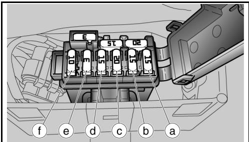
04_24
ABS
ABS
ABS
ABS
ABS
ABS
ABS
ABS
ABS
vocado el,inconveniente.Sustituir el fusible,si esta dañado, con othero delismo amperaje

NOTA
SI SE UTILIZA UN FUSIBLE DE REServa, COLOCAR UNO IGUAL EN EL ALOJAMIENTO CORRESPONDIENTE.
-forky: A new, small, and simple way of dividing a large number of items.
-Participles: The principal parts of a projective system.
-Participales de la construction: The construction of a building.
-Participales de la construction: The construction of a building.
-Participales de la construction: The construction of a building.
NOTA
EXTRAER LOS FUSIBLES DE 30A IMPLICA PONER A CERO LAS FUNCTIONS: RELOJ DIGITAL, INFORMACIONES DE VIAJE Y MEDICIONES CRONOMÉTRICAS.
- Replace the damaged fuse with one of equal current rating.
NOTE
WHEN YOU USE ONE OF THE SPARE FUSES, REMEMBER TO ADD A NEW ONE OF EQUAL RATING TO THE FUSE BOX.
- To check main fuses carry out the same operations described above for auxiliary fuses.
NOTE
REMOVING THE 30 A FUSES RESETS THESE FUNCTIONS: DIGITAL CLOCK, TRIP INFORMATION AND CHRONOMETRICAL TIMES.
DISPOSICION DE LOS FUSIBLES SECUNDARIOS
| Characterística | Descripción/Valor |
| (a) Fusible de 15 A | Stop, claxon, iluminación pulsador HAZARD, bobina relé luces |
| (b) Fusible de 15 A | Luces de posición, bobina relé arranque, passing |
| (c) Fusible de 20 A | Bomba de gasolina, bobinas, inyectores |
| (d) Fusible de 15 A | Quemador lambda, bobina relé inyección secundario, bobina relé arrancador, alimentación sensor de velocidad |
| (e) Fusible de 3 A | Positivo permanente, alimentación centralita ECU |
| (f) Fusible de 10 A - ABS | Sistema ABS |
| 3 A - 15 A - 20 A | Fusibles deresha |
DISPOSICION FUSIBLES ABS
| Característica | Descripción/Valor |
| (g) Fusible de 40 A - ABS | Bomba hidráulica ABS |
AUXILIARY FUSES DISTRIBUTION
| Specification | Desc./Quantity |
| (a) 15A fuse | Stop, horn, HAZARD button lighting, light relay coil |
| (b) 15A fuse | Taillights, start-up relay coil, passing |
| (c) 20A fuse | Fuel pump, coils, injectors |
| (d) 15A fuse | Lambda burner, auxiliary injection relay coil, start-up relay coil, speed sensor power |
| (e) 3A fuse | Permanent positive, power to ECU |
| (f) 10A fuse - ABS | ABS system |
| 3A - 15A - 20A | Spare fuses |
ABS FUSE DISTRIBUTION
| Specification | Desc./Quantity |
| (g) 40A fuse - ABS | ABS hydraulic pump |
(h) Fusible de 25 A - ABS
Electroválvula ABS
(h) 25A fuse - ABS
ABS solenoid valve
DISPOSICION DE LOS FUSIBLES PRINCIPALES
| Characterística | Descripción/Valor |
| (i) Fusable de 30 A | De世家 la batería al regulator de tensión |
| (j) Fusable de 30 A | De世家 batería a llave y fusibles secundarios 'c' y 'd' |
| - | Un fusible es de réserve |
ARRANGEMENT OF MAIN FUSES
| Specification | Desc./Quantity |
| (i) 30A fuse | From battery to voltage regulator |
| (j) 30A fuse | From battery to key and auxiliary fuses 'c' and 'd' |
| - | There is one spare fuse |
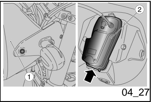
Bombillas (04_27, 04_28, 04_29, 04_30)

ANTES DE SUSTITUIR UNA BOMBILLA, COLOCAR EL INTERRUPTOR DE ENCENDIDO EN LA POSICION «OFF» Y ESPERAR ALGUNOS MINUTOS PARA PERMITIR EL ENFRIAMENTO DE LA MISMA.
SUSTITUIR LA BOMBILLA USANDO GUANTES LIMPIOS O USANDO UN PANO
Lamps (04_27, 04_28, 04_29, 04_30)

BEFORE REPLACING A BULB, TURN THE IGNITION SWITCH TO «OFF» AND WAIT A FEW MINUTES FOR THE BULB TO COOL OFF.
Wear CLEAN GLOVES OR USE A CLEAN DRY CLOTH TO REPLACE THE BULB.
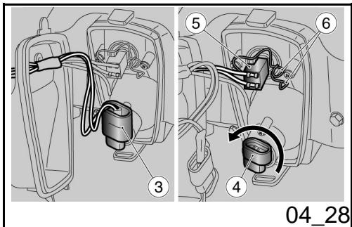
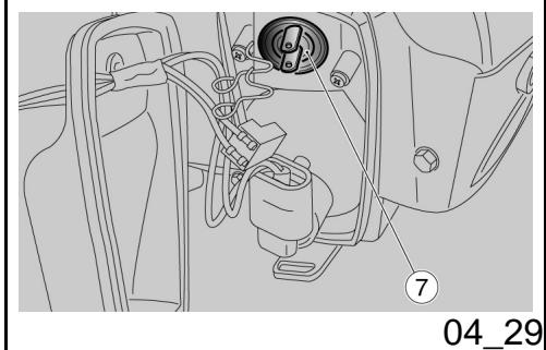
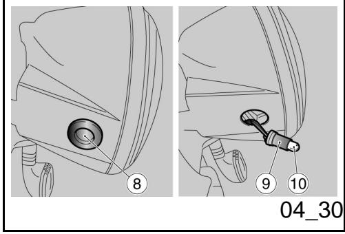
LIMPIO Y SECO.
NO DEJAR HUELLAS EN LA BOMBILLA PORQUE PODRIA CAUSAR SU SOBRECALENTAMENTO Y LUEGO SU ROTURA. SI SE TOCA LA BOMBILLA CON LAS MANOS DESNUDAS, LIMPIAR CON ALCOHOL LAS EVENTUALES HUELLAS PA-RA EVITAR QUE SE DANE.
NO FORZAR LOS CABLES ELECTRICOS.
SUSTITUCION BOMBILLAS FARO DELANTERO
En el faro delantero está alojadas:
- una bombilla de luz de carretera (inferior).
- una bombilla luz de cruce (superior);
- una bombilla de luz de posicion (inferior);
Antes de la sustitución de las bombillas, esnecessary quitar elGrupo optico delantero.
Para sustituir las bombillas luces de carretera y de cruce:
- Quitar el faro (1).
- Quitar la tapa (2), empujándola ha cía arriba, liberar la pieza inferior y sacar finalmente la lengüeta superior de su alojamento.
DO NOT LEAVE PRINTS ON THE BULB AS THIS MAY CAUSE IT TO OVERHEAT OR EVEN BLOW OUT. IF YOU TOUCH THE BULB WITHOUT WEARING GLOVES, CLEAN OFF PRINTS WITH ALCOHOL TO AVOID DAMAGING THE BULB.
DO NOT FORCE ELECTRICAL CABLES.
FRONT HEADLAMP BULB REPLACEMENT
In the front headlight there are:
- One full beam headlight bulb (lower).
- One dipped headlight bulb (upper);
- One tail light bulb (lower).
Before replacing the bulbs, it is necessary to remove the front headlight assembly.
To replace the high-beam and low-beam headlight bulbs:
- Remove the headlight (1).
- Remove the cover (2), pressing upwards, release the lower clip and slide the upper tab out of its seat.
BOMBILLA LUX DE CARREtera
- Desconectar el conector (3).
Girar la tuerca de bloqueo en sentido contrario a las agujas del reloj y sacar el cuerpo de la bombilla (4). - Sustainir por uno nuevo identico.
- Volver a montar el cuerpo de la bombilla en el alojamento correspondiente y girarlo en el sentido de las agujas del reloj hasta que quede bloqueado.
- Conectar el conector (3).
HIGH-BEAM BULB
- Disconnect the connector (3).
- Turn the bulb locking device in anticlockwise direction and remove the bulb (4).
- Replace with a new identical bulb.
- Reinstall the bulb in its seat and turn the locking device in clockwise direction until it is tight.
- Connect the connector (3).
BOMBILLA LUX DE CRUCE
- Sujetar el conector eletrico de la bombilla (5), tirar de el y desconectaro de la bombilla.
Desenganchar los dos extremos del muelle de retencion (6).
Extraer la bombilla (7) de su alojamento. - Instalar correctamente, en el portalámparas, una bombilla del@mismo tipo hacerendo coincidir las marcas de colocacion.
- Vuelva a enganchar los muelles de retencion (6).
- Conectar el conector (5).
LOW-BEAM BULB
Pull out the electrical connection to the bulb (5), and disconnect it from the bulb.
- Press together the two ends of the retainer spring (6).
Pull the bulb (7) out of its seat.
Install a bulb of the same type correctly in the bulb holder, aligning the positioning seats.
- Refit the retainer springs (6).
- Connect the connector (5).
BOMBILLA LUX DE POSICION
- Quitar la goma de cierre (8).
- Sujetar el portalámparas de luz de posición (9), tirar de el y extraerlo de su alojimiento.
- Sacar la bombilla (10) y sustituirla por una del mesmo Modelo.
- Volver a montar el portalámparas (9) en su alojimiento y la goma de cierre (8).
TAIL LIGHT BULB
- Remove the rubber seal (8).
Pull out the tail light bulb holder (9) from its seat. - Remove the bulb (10) and replace it with another of the same type.
- Reinstall the bulb holder (9) in its seat and install the rubber seal (8).
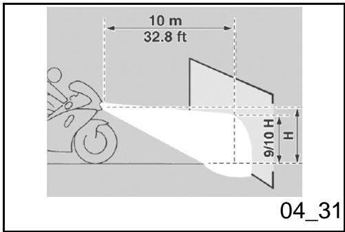
Regulación projector (04_31, 04_32, 04_33)
NOTA
EN FUNCION DE LO PREVISTO POR LA LEGISLACION EN VIGENCIA EN EL PAís DONDE SE UTILICE EL VEHÍCULO, PARA EL CONTROL DE LA ORIENTACION DEL HAZ LUMINOSO SE DEBEN ADOPTAR PROCEDIMENTOS ESPECÍNICOS.
Headlight adjustment (04_31, 04_32, 04_33)
NOTE
IN COMPLIANCE WITH LOCAL LEGAL REQUIREMENTS, SPECIFIC PROCEDURES MUST BE FOLLOWED WHEN CHECKING LIGHT BEAM ADJUSTMENT.
Para la regulación vertical del haz luminoso:
- Colocar el vehiculo en posicion vertical.
- Regular la inclinacion con el tornillo (1).
In order to carry out vertical adjustment of the light beam:
Position the scooter on the level.
- Adjust the inclination by turning screws (1).
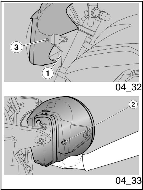
Para la regulación horizontal del haz luminoso:
- Colocar el vehiculo en el caballete.
- Guitar el grupo óptico delantero.
- Manteniendo el faro levantado, mover el tornillo (2) para regular la orientacion del haz luminoso.
- Volver a colocar el grupo optico delantero.
- Si la orientación es correcta, aplar los dos tornillos (3).
In order to carry out horizontal adjustment of the light beam:
- Rest the scooter on its stand.
- Remove the front headlight assembly.
- Holding the headlight raised, turn screw (2) to adjust the orientation of the light beam
. Reposition the front headlight as- assembly - If the orientation is correct, tighten the two screws (3).
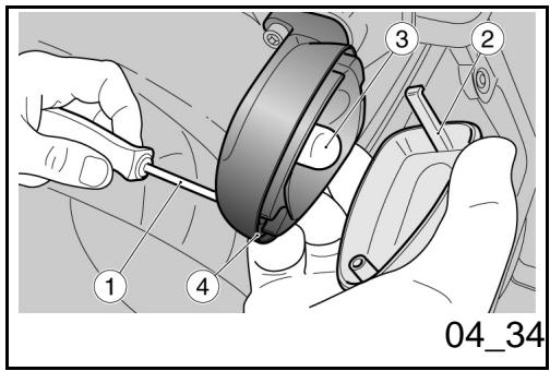
Indicadores de direccion delanteros (04_34)
Desenroscar y quitar el tornillo (1).
- Quitar la pantalla de proteccion (2) con mucho cuidado para no romper el diente de encastre.
- Empujar la bombilla (3) con moderation y girarla en sentido contrario a las agujas del reloj.
Extraer la bombilla (3) de su aloja
Front direction indicators (04_34)
- Loosen and remove the screw (1).
- Remove the protective screen (2), proceeding with caution in order not to break off the retainer tabs.
- Press the bulb (3) in slightly and turn in anticlockwise direction.
- Remove the bulb (3) from its seat.
Install a bulb of the same type in the
miento.
- Introducir una bombilla del mesmo modelo en el portalámparas, comoendo coincidir las dos espigas guía con las guías respectivas del portalámparas.
bulb holder, aligning the two guide pins with the corresponding guides on the bulb holder.
Grupo optico trasero
La moto cuenta con un faro trasero con LED, por lo tanto para su sustitución es acontejalble dirigirse a un Concesionario Oficial Moto Guzzi.
Rear optical unit
This vehicle has a LED rear headlamp, have it replaced at an Official Moto Guzzi Dealer.
Indicadores de direccion traseros
Para la sustitución de las bombillas de los intermitentes traseros proceder de la mesma forma que con los intermitentes delanteros.
Rear turn indicators
To replace the rear turn indicator bulbs follow the same procedure described for front turn indicators.
Luz plac
Dada la complejidad de la operation se aconseja dirigirse a un Concesionario Oficial Moto Guzzi.
Number plate light
Have this bulb replaced at an Official Moto Guzzi Dealer since it is very complex.
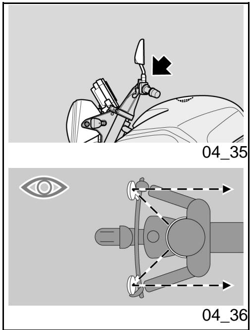
Espejos retrovisores
(04_35, 04_36)

NUNCA CONDUZCA CON LOS ESPEJOS RETROVISORES GIRADOS INCORRECTAMENTE.
ASEGURARSE SIempre, ANTES DE PARTIR, DE QUE SE ENCUESTREN EN POSICION DE TRABAJO Y CORRECTAMENTE REGULADOS.
Extraer los espejos retrovisores:
- Posicionar el vehiculo en el caballete.
- Aflojar la tuerca de bloqueo.

AL VOLVER A MONTAR, ASEGURARSE, ANTES DE APRETAR LA TUERCA DE BLOQUEO, QUE LA BARRA QUE SOSTIENE EL ESPEJO RETROVISOR ESTE ORIENTADA DE TAL MODE QUE RESULTE ALINEADA CON EL MANILLAR.
- SACar hacia arriba y extraer el gruppo espejo retrovisorcomplete.
Eventually repetir la operation para ex
Rear-view mirrors (04_35, 04_36)

DO NOT RIDE WITH REAR-VIEW MIRRORS INCORRECTLY SET.
BEFORE RIDING OFF, ALWAYS MAKE SURE THEY ARE CORRECTLY ADJUSTED TO RIDE.
Rear-view mirrors removal:
- Place the vehicle on its stand.
- Loosen the locking nut.

UPON REFITTING AND BEFORE TIGHTENING THE LOCKING NUT, MAKE SURE THAT THE REAR VIEW MIRROR SUPPORT STEM IS ALIGNED WITH THE HANDLEBAR.
- Slide up and remove the complete rear-view mirror unit.
Repeat the procedure to remove the other
traer elOTHERESEJEROTRVOISOR.
Regulación espejos retroviadores:
- Subir al vehiculo en posicion de conducccion.
- Girar el espejo regulando correctamente la inclinación.
Repetir el mesmo procedimiento para regular elOTHERESpejo retrovisor.
- Contralar que no estén sueños o con fango.
rear-view mirror, if necessary.
Rear-view mirrors adjustment:
Get on the vehicle in riding position.
- Turn mirror and adjust the correct angle.
Repeat the procedure to adjust the other mirror.
Make sure there is no dirt or mud.
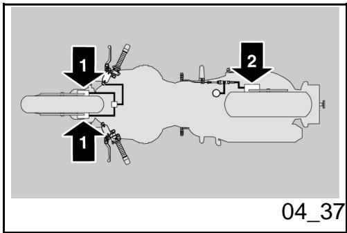
Freno de disco delantero y trasero

UN DISCO SUCIO ENSUCIA LAS PASTILLAS, CON LA CONSIGUIENTE REDUCIOn DE LA EFICACIA DE FRENADO.
LAS PASTILLAS SUCIAS SE DEBEN SUSTITUIR, MIENTRAS QUE EL DISCO SUCIOSE DEBE LIMPIAR CON UN PRODUCTO DESENGRAANTE DE ALTA CALIDAD.
ATENCLON
PARA EXTRAER LA RUEDA TRASERA DIRIGIRSE A UN CONCESIONARIO OFICIAL MOTO GUZZI.
Front and rear disc brake

A DIRTY DISC SOILS THE PADS, LEADING TO LOSS OF BRAKING.
REPLACE DIRTY PADS AND CLEAN AGAIN THE DIRTY DISC USING A TOP QUALITY DEGREASING PRODUCT.
CAUTION
CONTACT AN OFFICIAL MOTO GUZZI DEALER TO REMOVE THE REAR WHEEL.
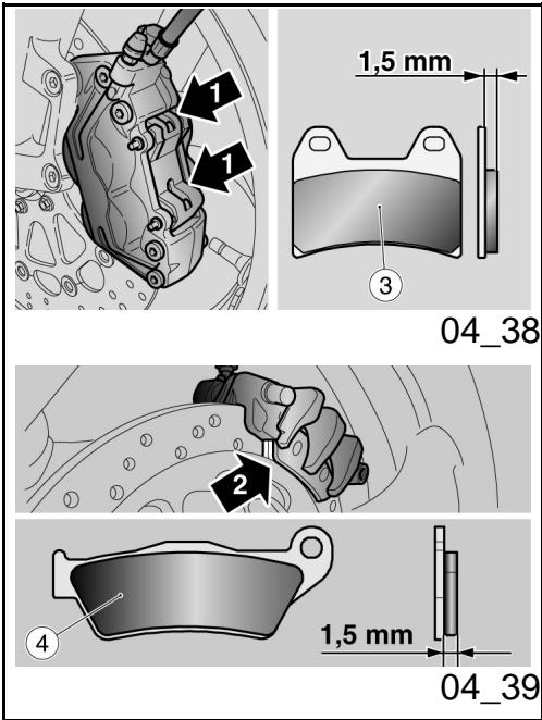
Freno de disco delantero y trasero (04_37, 04_38, 04_39)

CONTROLLER EL DESGASTE DE LAS PASTILLAS DE FRENOS SOBRETodo ANTES DE CADA VIAJE.
Para realizar el control rápido del desgaste de las pastillas:
- positional en vehiculo sobre el caballete.
-
Realizar un control visual entre el disco y las pastillas operando:
-
desde arriba y desde abras,para la pinza del freno delantero (1);
- sobre elazo opuesto de la moto, a工程技术 de la llanta, para la pinza del freno trasero (2).
ATENCIón
EL CONSUMO, SUPERADO EL LIMITE DEL MATERIAL DE FRIICION, CAUSA RIA EL CONTACTO DEL SOPORTE METÁLICO DE LA PASTILLA CON EL DISCO, CON EL CONSIGUIENTE RUIDO METÁLICO Y ESCAPE DE CHISPAS DE LA PASTILLA; LA EFICACIA DE FRENADO, LA SEGURIDAD Y EL BUEN ESTADO DEL
Front and rear disc brake (04_37, 04_38, 04_39)

CHECK BRAKE PADS FOR WEAR MAINLY BEFORE EACH RIDE.
To carry out a quick pad wear check:
- place the vehicle on its stand.
-
Visually inspect the area between disc and pads as follows:
-
look from above at the rear to check the front brake calliper (1);
- on the opposite side of the vehicle and through the rim, check the rear brake calliper (2).
CAUTION
EXCESSIVE WEAR OF FRICTION MATERIAL MAKES THE PAD METAL SUPPORT GET INTO CONTACT WITH THE DISC, WHICH RESULTS IN A METALLIC NOISE AND SPARKS IN THE CALLIPER; THIS COMPROMISES BRAKING EFFICIENCY AND SAFE RIDING AS WELL AS DAMAGES THE DISC.
DISCO QUEDARIAN DE ESTE MODO COMPROMETIDOS.
Si el espesor del material de friccion (incluo de una sola pastilla delantera (3) o trasera (4)) se enquirytra reducido hasta aproximamente 1,5 mm. (0.06 pulgadas) (o si uno solo de los indicadores de desgaste no es visible) hacer sustituir todas las pastillas de las pinzas del freno, dirigiendose a un Concesionario Oficial Moto Guzzi.
If the friction material thickness (even of one front (3) or rear (4) pad) is reduced to a value of about 1.5mm (0.06 in) (or even if one of the wear indicators is not very visible), contact an Official Moto Guzzi Dealer to replace all the calliper pads.
Inactividad del vehiculo (04_40)
En caso de una larga inactividad del vehiculo:
Extraer la bateria.
Lavarysecarelvehiculo.
- Pasar cera en las superficies pintadas.
Inflar los neumáticos.
- Situar el vehiculo en un local no ca-tefashionado, libre de humedad, protegido de los rayos solares en donde las variaciones de temperas sean minimas.
- Colocar y atar una Bolsa de plástico en el extremo del escape del silenciador para evitar que ingrese humedad.
Periods of inactivity (04_40)
In case of prolonged vehicle inactivity:
- Remove the battery.
- Wash and dry the vehicle
- Polish painted surfaces with wax.
Inflate tyres. - Store the vehicle in a cool, dry place, away from sunlight and with steady temperature.
- Wrap and tie a plastic bag around the exhaust pipe openings to keep moisture out.
CAUTION
PLACE A SUITABLE SUPPORT UNDER THE VEHICLE TO KEEP THE TYRES OFF THE GROUND.
ATENCLON
SE ACONSEJA COLOCAR EL VEHICULO SOBRE SOSTENES ESTABLES QUE MANTENGAN AMBOS NEUMÁTICOS LEVANTADOS DEL PISO.
Cubrir el vehiculo evitando usar materiales plácicos impermeables.
ATENCLON
PARA EVITAR QUE SE DETERIORE LA BATERIA, PROCEDER COMO SE HA INDICADO PARA LOS PERIODOS DE INACTIVIDAD PROLONGADA.
Cover the vehicle. Avoid using plastic or waterproof materials.
CAUTION
TO AVOID BATTERY DETERIORATION, FOLLOW THE PROCEDURE DESCRIBED FOR PROLONGED INACTIVITY.
Limpieza del vehiculo (04_41, 04_42, 04_43)
Limpiar frecuentemente el vehiculo si se utilizes en zonas o en conditiones de:
- Contaminación atmosférica (ciudad y zonas industriales).
Salinidad y humedad de la atmóse- rara (zonas marinas, clima calido y humedo). - Partículares conditiones ambientales/estaciones (uso de sal, produits químicos anticongelantes en carreteras durante el periodo invernal).
Se debe dedicar especial atencion
Cleaning the vehicle (04_41, 04_42, 04_43)
Clean the vehicle frequently when it is exposed to adverse conditions, such as:
Air pollution (cities and industrial areas).
- Atmospheric salinity and humidity (seashore areas, hot and wet weather).
- Special ambient/seasonal conditions (use of salt, anti-icing chemical products on the roads in winter).
Make sure to clean off any industrial residue and pollutants, tarmac, dead insects, bird droppings etc.
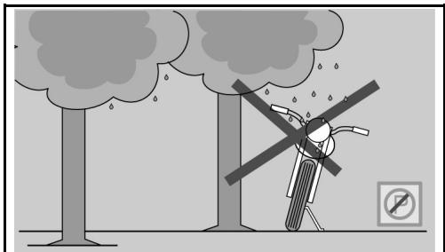
04_42
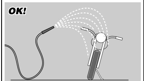
04_43
para evaporar que en la carrocería queden depósitos, residuos de polvos industriales y contaminantes, manchas de alquitrán, insectos muertos, increimientos de pájaros, etc.
- Evitar aparcar el vehiculo bajo de los árboles. En的一些estaciones, de los árboles caen residuos, resinas, frutos y hojas que contienen sustancias químicas dañinas para la pintura.
ATENCIón

ANTES DE LAVAR EL VEHICULO, TAPAR LAS TOMAS DE AIRE DE ASPIRACION DEL MOTOR Y LOS ESCAPES DEL SI-LENCIADOR.
ATENCLON


DESPUÉS DE LAVAR EL VEHÍCULO, LA EFICIENCY DEL FRENADO PODRÍA VERSE MOMENTÁNEAMENTE COMPROMETIDA A CAUSA DE LA PRESENCIA DE AGUA EN LAS SUPERFICIES DE FRIÇION DE LA INSTALLACION DE FRENOS. ES NECESARIO PREVER DISTANCIAS
from the vehicle fairings.
- Avoid parking the vehicle under trees. Resins, fruits or leaves falling from trees may contain aggressive chemical substances that may damage the paintwork.
CAUTION

BEFORE WASHING THE VEHICLE, COVER THE ENGINE AIR INTAKES AND THE EXHAUST PIPES.
CAUTION


AFTER CLEANING YOUR SCOOTER, BRAKING EFFICIENCY MAY BE TEMPORARILY AFFECTED DUE TO THE PRESENCE OF WATER ON THE FRICTION SURFACES OF THE BRAKING CIRCUIT. CALCULATE A LONGER BRAKING DISTANCE IN ORDER TO AVOID ACCIDENTS. BRAKE REPEATEDLY TO RESTORE NORMAL OPERATION. CARRY OUT THE PRELIMINARY CHECKS.
MAYORES DE FRENADO PARA EVITAR ACCIDENTES. ACCIONAR REPETIDAMENTE LOS FRENOS PARA RESTABLECER LAS CONDICIONES NORMALES. EFFECTUAR LOS CONTROLES PRELIMINARES.
Para eliminar la suciedad y el fango depositados en las superficies pintadas, se debe utilizar unchorro de agua a bajo presión, maior cuidadosamente las partes sucias, eliminar el fango y socidades con una esponja suave para carrocería, embebida en mucha agua y champú (2 - 4% partes de champú en agua). Posteriormente'enjuagar con abundante agua y secar con una gamuza. Para limpar las partes exteriores del motor, utilizing detergente desengrasante, pinceles y trapos Las partes de aluminio anodizzato o pintado como horquillas, llantas, chasis, estribos, etc., deben ser lavadas con jabón neutro y agua. El uso de detergentes demasiado agresivos pueda alterar el tratimiento de superficie de这些 componentes. El uso de detergentes demasiado agresivos能把 alterar el tratamento de superficie de这些东西 componentes.

PARA LA LIMPIEZA DE LOS FAROS, UTILizar UNA ESPONJA EMBEBIDA EN DETERGENTE NEUTRO Y AGUA, FROTANDO CON DELICADEZA LAS SUPERFICIES
To clean off dirt and mud deposited from painted surfaces, soften caked dirt with a low-pressure water jet. Sponge off using a car body sponge soaked in a car body shampoo and water solution (2 ÷ 4% parts of shampoo). Then rinse with plenty of water, and dry with a chamois leather. To clean the engine outer parts, use degreasing detergent, brushes and old cloths. Anodised or painted aluminium parts such as forks, rims, frame, footrests etc. should be washed using water and mild soap. Using aggressive detergents may damage the surface treatment of these components. Using aggressive detergents may damage the surface treatment of these components.

TO CLEAN THE HEADLIGHTS USE A SPONGE SOAKED IN WATER AND MILD DETERGENT, RUBBING THE SURFACE GENTLY AND RINSING FREQUENtLY WITH PLENTY OF WATER. REMEMBER TO CLEAN THE SCOOTER CAREFULLY BEFORE ANY POLISHING WITH SILICON WAX. DO NOT POLISH MATT-PAINTED
Y ENJUAGANDO FRECENTEMENTE CON ABUNDANTE AGUA. SE RECURDERA QUE EL LULARDO CON CERA SILICONADA SE DEBE REALizar DESPUES DE UN CUIDADOSO LAVADO DEL VEHICULO. NO LULARR CON PASTAS ABRASI-VAS LA PINTURA OPACA. NO LAVAR AL SOL, ESPECIALMENTE EN VERANO, CON LA CARROCERIA TODAVIA CALIENTE, PORQUE SI EL CHAMPU SE SECA ANTES DE ENJUAGARLO PODRIA CAUSAR DANOSA LA PINTURA.
ATENCIón

NO UTILIZAR AGUA (O LÍQUIDOS) A UNA TEMPERATUREA SUPERIOR A LOS 40^ (104^) PARA LA LIMPIEZA DE LOS COMPONENTES DE PLASTICO DEL VEHICULO. NO DIRIGIR CHORROS DE AGUA O DE AIRE A ALTA PRESION O CHORROS DE VAPOR EN LAS SIGUIENTES PARTES: CUBOS DE LAS RUELAS, MANDOS SITUADOS EN EL LADO DERECHO E IZQUIERDO DEL MANILLAR, COJINETES, BOMBAS DE FRENOS, INSTRUMENTOSE INDICadores, ESCAPE DEL SILENCIADOR, INTERRUPTOR DE ENCENDIDO / BLOQUEO DEL MANILLAR. NO UTILIZAR ALCOHOL NI SOLVENTES PARA LA LIMPIEZA DE LAS PARTES DE GOMA O PLASTICO, NI PARA EL ASIENTO. UTILIZAR, EN CAMBIO, AGUA Y JABON NEUTRO.
SURFACES WITH POLISHING PASTE. THE VEHICLE SHOULD NEVER BE WASHED IN DIRECT SUNLIGHT, ESPECIALLY DURING THE SUMMER WHEN THE BODYWORK IS STILL HOT, AS THE SHAMPOO, MAY DAMAGE THE PAINTWORK IF IT DRIES BEFORE BEING RINSED OFF.
CAUTION

DO NOT USE WATER (OR LIQUIDS) AT A TEMPERATURE HIGHER THAN 40^ (104^) TO CLEAN THE PLASTIC COMPONENTS OF THE VEHICLE. DO NOT AIM HIGH PRESSURE AIR/WATER JETS OR STEAM JETS AT THE FOLLOWING PARTS: WHEEL HUBS, CONTROLS ON THE RIGHT AND LEFT SIDE OF THE HANDLEBAR, BEARINGS, BRAKE PUMPS, INSTRUMENTS AND INDICATORS, SILENCER, IGNITION SWITCH/STEERING LOCK. DO NOT CLEAN ANY RUBBER OR PLASTIC SADDLE COMPONENTS WITH ALCOHOL OR SOLVENTS: USE WATER AND MILD SOAP ONLY.
CAUTION
DO NOT USE SOLVENTS OR PETROL BYPRODUCTS (ACETONE, TRICHLOROETHYLENE, TURPentine, PETROL, THINNERS) TO CLEAN THE SADDLE. USE INSTEAD DETERGENTS WITH SUR
ATENCLON
PARA LIMPIAR EL ASIENTO NO UTILIZAR SOLVENTES O DERIVADOS DE PETROLEO (ACETONA, TRICLOROETILENO, TREMENTINA, BENCINA, DILUYENTES) SE PUEDEN UTILizar DETERGENTES QUE CONTENGAN TENSIOACTIVOS NO SUPERIORES AL 5% (JABON NEUTRO, DETERGENTE DESENGRASANTE O ALCOHOL).
SECAR CON CUIDADO EL ASIENTO AL FINALIZAR LA LIMpieZA.
ATENCLON

NO APLICAR EN EL ASIENTO CERA DE PROTECCION PARA EVITAR RESBALAMIENTOS.
FACE ACTIVE AGENTS NOT EXCEEDING 5% (NEUTRAL SOAP, DEGREASING DETERGENTS OR ALCOHOL).
DRY THE SADDLE WELL AFTER CLEANING.
CAUTION

DO NOT APPLY PROTECTIVE WAX ON THE SADDLE OR IT MAY BECOME SLIPPERY.
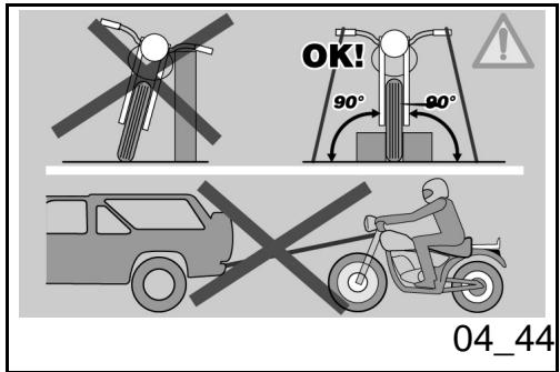
Transporte (04_44)
Antes de transporte el vehiculo es necesario vinciar@cuidadosamente el deposito de combustible,controlando que quede complemente seco.
Durante el desplazimiento el vehiculo debemaintener una posicion vertical, estar biensujetado y tener acoplada la prima marcha, para evitar eventuales perdidas de combustible y de aceite.
Transport (04_44)
Before transporting the vehicle, empty the fuel tank well and make sure it is perfectly dry.
During transport the vehicle must be well secured in an upright position and first gear must be engaged to avoid fuel and oil leaks.
IN CASE OF FAILURE, DO NOT HAVE THE VEHICLE TOWED. CONTACT A ROAD ASSISTANCE SERVICE.
EN CASO DE AVERIA NO REMOLCAR EL VEHICULO, SINO SOLLICITAR LA INTERVENTION DE UN MEDIO DE AUXILIO.
1200 sport

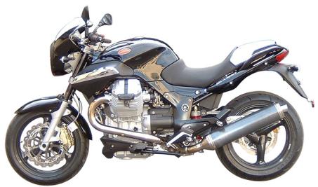
Cap. 05
Datas tíncicos
Chap. 05
Technical data
DATI TECHNICI
| Característica | Descripción/Valor |
| Longitud máx. | 2195 mm.(86.4 in) |
| Anchura máx. | 870 mm.(34.2 in) |
| Altura máx | 1125 mm.(44.3 in) |
| Altura del asiento | 800 mm.(31.5 in) |
| Distancia entre ejes | 1495 mm.(589 in) |
| Altura libre minima desde el piso | 185 mm.(72.8 in) |
| Peso enorden de marcha | 248 Kg (547 lb) |
| Motor - modelos | V 1200 IE |
| Motor - Tipo | bicilíndrico transversal de V 90°, 4 tiempos |
| Motor - número cilindros | 2 |
| Motor - Cilindrada | 1151 cc (70 cuin) |
| Motor - diámetro interior/carrera | 95 - 81.2 mm. (3.74 - 3.20 in) |
| Motor - Relación de compresión | 9,8: 1 |
| Potencia Tmaxima | mas de 65 kW (90 CV) a 7500 rev/min (rpm) |
| Motor - Arranque | eléctrico |
| Motor - N° revoluciones del motor en ralentí | 1100 +/- 100 rev/min. (rpm) |
| Motor - Embrague | bidisco en seco |
DATI TECHNICI
| Specification | Desc./Quantity |
| Max. length | 2195 mm (86.4 in) |
| Max. width | 870 mm (34.2 in) |
| Max. height | 1125 mm (44.3 in) |
| Saddle height | 800 mm (31.5 in) |
| Centre to centre distance | 1495 mm (589 in) |
| Minimum ground clearance | 185 mm (72.8 in) |
| Kerb weight | 248 kg (547 lb) |
| Engine - model | V 1200 IE |
| Engine - Type | 90° transversal V-twin, 4-stroke |
| Engine - Number of cylinders | 2 |
| Engine - Engine capacity | 1151 cc (70 cu.in.) |
| Engine - bore/stroke | 95 x 81.2 mm (3.74 x 3.20 in) |
| Engine - Compression ratio | 9.8:1 |
| Maximum power | over 65 kW (90 CV) at 7500 rpm |
| Engine - Start-up | electric |
| Engine - No of engine revs at idle speed | 1100 +/- 100 rpm |
| Engine - Clutch | dry, twin disc |
| Engine - Lubrication system | pressure-fed system adjusted |
| Motor - Sistema de lubricación | sistema a presión regulado por válvulas y bomba de engranajes |
| Motor - Filtro aire | con cartucho, en seco |
| Motor - Refrigeración | aire |
| Cambio - Tipo | meccánico con 6 relaciones con mando a pedal en el lado izquierdo del motor |
| Relación de transmisión | Principal de engranajes 24/35 |
| Relación de transmisión 1° marcha | 17 / 38 (secundaria) |
| Relación de transmisión 2° marcha | 20 / 34 (secundaria) |
| Relación de transmisión 3° marcha | 23 / 31 (secundaria) |
| Relación de transmisión 4° marcha | 26 / 29 (secundaria) |
| Relación de transmisión 5° marcha | 31 / 30 (secundaria) |
| Relación de transmisión 6° marcha | 29 / 25 (secundaria) |
| Relación de transmisión final | 12 / 44 (con cardan) |
| Capacidad - combustible | incluyendo laerva 23 litres (41.8 pt) |
| through valves and gear pump | |
| Engine - Air filter | cartridge, dry |
| Engine - Cooling | air |
| Gearbox - Type | mechanic, 6 gear with pedal lever on the left hand side of the engine |
| Gear ratio | Primary gears 24/35 |
| 1° gear ratio | 17 / 38 (auxiliary) |
| 2° gear ratio | 20 / 34 (auxiliary) |
| 3° gear ratio | 23 / 31 (auxiliary) |
| 4° gear ratio | 26 / 29 (auxiliary) |
| 5° gear ratio | 31 / 30 (auxiliary) |
| 6° gear ratio | 29 / 25 (auxiliary) |
| Final gear ratio | 12 / 44 (shaft) |
| Capacity - fuel | 23 litres (41.8 pt) including reserve |
| Capacity - fuel reserve | 4 litres (7.3 pt) |
| Capacity - engine oil | oil and filter replacement: 3600 cc (220 cu.in.) |
| Capacidad - reserve del combustible | 4 litres (7.3 pt) |
| Capacidad - aceite motor | sustitución aceite y filtro: 3600 cc (220 cuin) |
| Capacidad - aceite cambio | 500 cc (30.5 cuin) |
| Capacidad - aceite de transmisión | 380 cc (23.2 cuin) |
| Capacidad - aceite horquilla | para cada vástago 400 ± 2,5 cc (24.4 ± 0.15 cuin) |
| Plazas | 2 |
| Máxarga vehístico | 230 Kg (507 libras) (conductor + pasajero + equipaje) |
| Sistema de alimentación - tipo | ineccion electrónica multipoint, secuencial, puesta en fase Magneti Marelli IAW5A, sistemas alfa-n con stepper motor; 2 cuerpos mariposa de 45 mm. (1.77 pulgadas) con inyectores Weber LW031, sonda lambda en closed loop |
| Sistema de alimentación - difusor | diám. - 45 mm. (- 1.77 in) |
| Alimentación - combustible | gasolina sufper sin plomo, con número de octanos是最imo 95 (N.O.R.M.) y 85 (N.O.M.M.). |
| Capacity - gearbox oil | 500 cc (30.5 cu.in.) |
| Capacity - transmission oil | 380 cc (23.2 cu.in.) |
| Capacity - fork oil | for each stem 400 ± 2.5 cc (24.4 ± 0.15 cu.in.) |
| Seats | 2 |
| Vehicle max. load | 230 Kg (507 lb) (rider + passenger + luggage) |
| Fuel supply system - type | electronic multipoint sequential phased integrated electronic fuel injection, Magneti Marelli IAW5A, Alpha-N system with stepper engine; 2 throttle bodies of 45 mm (1.77 in) with Weber IW031 injector, lambda probe in closed loop |
| Fuel supply system - diffuser | diam. ---45 mm (1.77 in) |
| Fuel supply - fuel | premium unleaded petrol, minimum octane number 95 (NORM) and 85 (NOMM) |
| Spark plugs - inner | long life, NGK PMR8B |
| Spark plugs - outer | NGK BPR6ES |
| Spark plug - electrode gap | 0.6 - 0.7 mm (0.024 - 0.027 in) |
| Bujías - interiores | long life NGK PMR8B |
| Bujías - exteriores | NGK BPR6ES |
| Bujías - distancia entre electrosos | 0,6 - 0,7 mm. (0.024 - 0.027 in) |
| Chasis - Inclinación tubo de发展方向 | 25,30° |
| Chasis - tipo | Tubular en acero con alto limite de deformación elástica |
| Chasis - Avance | 120 mm.(4.72 in) |
| Instalación electrónica - Fusibles secundarios | 3 - 15 - 20 A (sólo para ABS 10 A) |
| Instalación electrónica - Fusibles ABS | 40 - 25 A |
| Instalación electrónica - Fusibles principales | 30 A |
| Suspensiones - trasera | monobrazo con varillaje progresivo, monoamortiguidor regulable en extensión y con puño ergonómico para la regulación de la precarga. carrera rueda 140 mm.(5.5 in) |
| Freno - delantero | doble disco flotante de acero inox diámetro 320 mm. (12.6 in) pinzas de 4 pistones diferenciados y contrapuestos |
| Chassis - Headstock angle | 25.30° |
| Chassis - type | High strength steel tube chassis |
| Chassis - Trail | 120 mm (4.72 in) |
| Electrical system - Auxiliary fuses | 3 - 15 - 20 A (only 10A for ABS) |
| Electrical system - ABS fuses | 40 - 25A |
| Electrical system - Main fuses | 30 A |
| Suspensions - rear | single arm suspension with progressive leverage, single shock absorber with adjustable rebound and with ergonomic hand grip for preloading adjustment. |
| 140 mm (5.5 in) wheel travel | |
| Brake - front | 320 mm (12.6 in) diam. twin floating disc in stainless steel, callipers with 4 different and counteracting plungers |
| brake - rear | 282 mm (11.1 in) diam. disc in stainless steel, calliper with two parallel plungers |
| Wheel rims - type | hollow 3-spoke rim in chilled cast aluminium alloy |
| Wheel rims - front | |
| freno - trasero | disco en acero inox diámetro 282 mm. (11.1 in), pinza de dos pistones paralelos |
| Llantas rueda - tipo | de 3 rayos en alección de aluminio fundidas en coquilla |
| Llanta rueda - delantera | 3,5 x 17" |
| Llantas rueda - trasera | 5,5 x 17" |
| apriete tuerca del perno rueda delantera | 80 Nm (59 ftlb) |
| Apriete tornillos rueda trasera | 110 Nm (81 ftlb) |
| Neumáticos - modelos | METZELER Roadtec Z6 - MICHELIN Pilot Road - DUNLOP D220 ST Sportmax |
| Neumáticos - Delantero medida | 120/70 - ZR 17" 58 W |
| Neumáticos - Delantero presión de inflado | 2,5 KPa (250 bar) |
| Neumáticos - Delantero presión de inflado con pasajero | 2,5 KPa (250 bar) |
| Neumáticos - Trasero medida | 180 / 55 - ZR 17" 73 W |
| Neumáticos - Traseros presión de inflado | 2,8 KPa (280 bar) |
| Neumáticos - Trasero presión de | 2,8 KPa (280 bar) |
| 3.5 " x 17" | |
| Wheel rims - rear | 5.5 " x 17" |
| front wheel pin nut tightening | 80 Nm (59 ftlb) |
| Rear wheel screw tightening | 110 Nm (81 ftlb) |
| Tyres - type | METZELER Roadtec Z6 - MICHELIN Pilot Road - DUNLOP Sportmax D220 ST |
| Tyres - front size | 120/70 - ZR 17" 58 W |
| Tyres - Front inflation pressure | 2.5 atm (250 kPa) |
| Tyres - Front inflation pressure with passenger | 2.5 atm (250 kPa) |
| Tyres - rear size | 180 / 55 - ZR 17" 73 W |
| Tyres - Rear inflation pressure | 2.8 atm (280 kPa) |
| Tyres - Rear inflation pressure with passenger | 2.8 atm (280 kPa) |
| Electrical system - battery | 12 V - 18 Amp/h |
| Electrical system - Generator | with permanent magnet, 12 V - 550 W |
| Bulbs - taillight | 12V - 5W |
| inflado con pasajero | |
| Instalación electrónica - bateria | 12 V - 18 Amp/h |
| Instalación electrónica - Generador | de magneto permanente 12 V - 550 W |
| Bombillas - luces de posición | 12V - 5W |
| Bombillas - luces de cruce | 12 V - 55 W H7 |
| Bombillas - luz de carretera | 12 V - 65 W H9 |
| Bombillas - luces intermitentes | 12 V - 10 W (anaranjado) |
| Bombillas - luces de posición trasera / stop | LED |
| Bombillas - iluminación instrumentos | LED |
| Bombillas - luz de matricula | 12V - 5W |
| Testigos - intermitentes | LED |
| Testigos - ABS | LED |
| Testigos - Alarma | LED |
| Testigos - Cambio en punto muerto | LED |
| Testigos - Caballete lateral bajo | LED |
| Bulbs - low-beam light | 12 V - 55 W H7 |
| Bulbs - high-beam light | 12 V - 65 W H9 |
| Bulbs - turn indicators | 12 V - 10 W (orange) |
| Bulbs - Rear tail light / stop light | LED |
| Bulbs - instrument panel lighting | LED |
| Bulbs - license plate light | 12V - 5W |
| Warning lights - turn indicators | LED |
| Warning lights - ABS | LED |
| Warning lights - Alarm | LED |
| Warning lights - Gear in neutral | LED |
| Warning lights - Side stand down | LED |
| Warning lights - high-beam light | LED |
| Warning lights - fuel reserve | LED |
| Warning lights - gear shift | LED |
| Warning lights - Antitheft device | LED |
| Suspensions - front | Hydraulic telescoping fork diam. 45 mm (1.77 in) |
| Testigos - luz de carretera | LED |
| Testigo -resherva de combustible | LED |
| Testigos -chio de marcha | LED |
| Testigos - antirrobo | LED |
| Suspensiones - delanteras | horquilla telescónica hidráulica diám. 45 mm (1.77 in) carrera 120 mm.(4.7 in) |
120 mm (4.7 in) travel
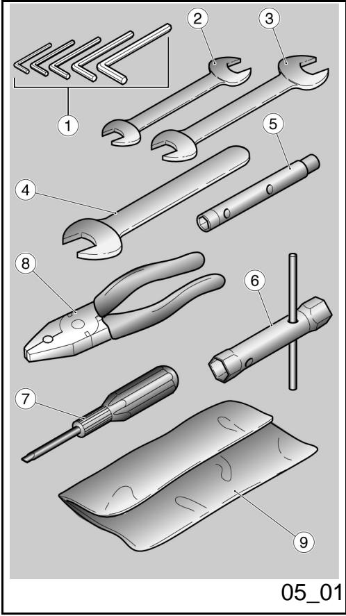
Herramentas enidotación (05_01)
La dotación de herramrientas comprende:
-llaves macho hexagonales plegadas 3,4, 5,6,mm.(1);
- llave de horquilla doble 8 - 10 mm. (2);
- llave de horquilla doble 13 - 14 mm. (3);
- Ilave de horquilla 19 mm. (4);
- llave de tubo 8 - 10 mm.. (5);
- llave de tubo 17 - 21 mm. para bujía (6) y regulación precarga horquilla;
-destornillador de doble punta cruz / corte (7);
- pinza (8);
- un sobre de contencion (9);
Peso máximo permitido: 5 Kg en el compartmento portadocumentos más 5 Kg en el compartmento kit herramrientas.
Kit equipment (05_01)
The tools supplied are:
- L-shaped Allen keys 3, 4, 5, 6 mm (1);
- 8 - 10 mm double open ended spanner (2);
- 13 - 14 mm double open ended spanner (3);
- 19 mm single open ended spanner (4);
- 8 - 10 mm box-spanner (5);
- 17 -21 mm box-spanner (6) for spark plugs and fork preload adjustment;
- crosshead / plain slot screwdriver (7);
- pliers (8);
-one toolkit pouch (9);
Maximum weight allowed: 5kg in the glove compartment); +5kg in the toolkit compartment.
1200 sport


Cap. 06
Elmantimiento
programado
Chap. 06
Programmed
maintenance
Tabla manutencion programada
Un mantenimiento adecuado constituye un factor determinante para una mayor duración del vehúculo en conditiones óptimas de funciona y rendimiento.
A tal fin Moto Guzzi dispuso una series de controles y de intervenciones de mantenimiento págas, que se detallan en el cuadro sinóptico que se muestra en la頁a sigeniente. Es recomendable que eventualesymesas anomalías de funcionaamento se informen inmediamente al Concesionario o Revendedor Autorizzato Moto Guzzi, sin esperar al suiviente control periodico para remediarlo.
Es indispensable能做到ar los controles periodicos en los intervals de kilometros y tiempos prescritos,apanas se alcanza el kilometraje previsto. Los controles periodicos demantimiento se deben efectuar punctualmente para la correctautilizacionde la garantia.Porequalquierotrainformacion relacionada conla modalidadde aplicacionde la Garantia y laexecution del"Mantenimientoprogramado",remitirse al"Manual de Garantia".
NOTA
EL TIEMPO PREVISTO PARA REALIZAR LAS OPERaciones DE MANTENIMIENT
Scheduled maintenance table
Adequate maintenance is fundamental to ensuring long-lasting, optimum operation and performance of your vehicle.
For this purpose, Moto Guzzi offers a set of checks and maintenance services (for payment), which are included in the summary table shown on the following page. Any minor faults should be reported without delay to an Authorised Moto Guzzi Dealer or Sub-dealer without waiting until the next scheduled service to solve it.
All scheduled maintenance services must be carried out at the specified times, even if the stated mileage has not yet been reached. Carrying out scheduled services on time is necessary to ensure your warranty remains valid. For further information regarding Warranty procedures and "Scheduled Maintenance", please refer to the "Warranty Booklet".
NOTE
CARRY OUT THE MAINTENANCE OPERATIONS AT HALF THE INTERVALS
EN CADA ARRANQUE
| Operación |
| Testigo presión aceite motor - controlar y limpiar, regular, lubricar o sustituir si es necesario |
| ANTES DE CADA VIAJE Y CADA 2000 KM (1250 MILLAS) |
| Operación |
| Desgaste pastillas de frenos - Controlar y limpiar, regular o sustituir si es necesario |
| FINAL DEL RODAJE (1.000 KM (625 MILLAS)) |
| Operación |
| Pernos de fijación bridas tubos de escape - Controlar y limpiar, regular, lubricar o sustituir si es NEEDario |
| Cables transmisión ymandos - controlar y limpiar, regular, lubricar o sustituir si es NEEDario |
AT EVERY START-UP
| Action |
| Engine oil pressure warning light - check and clean, adjust, grease or replace if necessary |
| BEFORE EACH RIDE AND EVERY 2000 KM (1250 MILES) |
| Action |
| Brake pad wear - Check and clean, adjust, grease or replace if necessary |
| AFTER-RUN 1000 KM (625 MILES) |
| Action |
| Exhaust pipe flange bolts - Check and clean, adjust, grease or replace if necessary |
| Bowden cables and controls - Check and clean, adjust, grease or replace if necessary |
| Cojinetes de direccion y juego direccion - Controlar y limpiar, regular, lubricar o sustituir si es Neededo |
| Discos de frenos - Controlar y limpiar, regular, lubricar o sustituir si esneededo |
| Filtro de aceite motor - sustitución |
| Horquilla - Controlar y limpiar, regular o sustituir si esneededo |
| Funcioncimiento general del vehiclulo - Controlar y limpiar, regular, lubricar o sustituir si esneededo |
| Instalaciones de frenos - Controlar y limpiar, regular, lubricar o sustituir si esneededo |
| Instalaciones de luces - Controlar y limpiar, regular, lubricar o sustituir si esneededo |
| Interruptores de seguridad - Controlar y limpiar, regular, lubricar o sustituir si esneededo |
| Aceite del cambio de velocidades - Sustituir |
| Aceite motor - Sustitución |
| Aceite de transmisión final - Sustituir |
| Neumáticos - Controlar y limpiar, regular o sustituir si esneededo |
| Presión de los neumáticos - Regular |
| Revoluciones motor en ralentí- Regular |
| Regulación juego de valvulas - Regular |
| Rueda - Controlar y limpiar, regular, lubricar o sustituir si esneededo |
| Ajuste pernos - Controlar y limpiar, regular, lubricar o sustituir si esneededo |
| Steering bearings and steering clearance - Check and clean, adjust, grease or replace if necessary |
| Brake discs - Check and clean, adjust, grease or replace if necessary |
| Engine oil filter - Replace |
| Fork - Check and clean, adjust, grease or replace if necessary |
| General vehicle operation - Check and clean, adjust, grease or replace if necessary |
| Braking systems - Check and clean, adjust, grease or replace if necessary |
| Light circuits - Check and clean, adjust, grease or replace if necessary |
| Safety switches - Check and clean, adjust, grease or replace if necessary |
| Transmission oil - change |
| Engine oil - Replacement |
| Final transmission oil - Change |
| Tyres - Check and clean, adjust, grease or replace if necessary |
| Tyre pressure - Adjust |
| Engine revs at idle speed - Adjustment |
| Valve clearance adjustment - Adjust |
| Wheels - Check and clean, adjust, grease or replace if necessary |
| Bolts, nuts and screws tightening - Check and clean, adjust, grease or replace if necessary |
| Battery terminals tightening - Check and clean, adjust, grease or replace if necessary |
| Ajuste bornes batería - Controlar y limpiar, regular, lubricar o sustituir si es besoino |
| Ajuste tornillos prisonereros culata - Regular |
| Ajuste tornillos culata - Regular |
| Sincronización cilindros - Controlar y limpiar, regular, lubricar o sustituir si es besoino |
| Suspensiones y ajuste - Controlar y limpiar, regular, lubricar o sustituir si es besoino |
| Desgaste pastillas de frenos - Controlar y limpiar, regular o sustituir si es besoino |
CADA 4 ANOS
Operación
Tubos combustible - Sustituir
Tubos frenos - Sustituir
CADA 5.000 KM (3125 MILLAS) - EN EL CASO DE CONDUCCION DEPORTIVA
Operación
Bujías exteriores - Sustituir
Filtro de aceite motor - sustitución
Vaciado del tubo de drenaje aceite de la caja del filtro - Limpiar
Head stud bolt tightening - Adjust
Head screws tightening - Adjust
Cylinder synchronisation - Check and clean, adjust, grease or replace if necessary
Suspensions and trim - Check and clean, adjust, grease or replace if necessary
Brake pad wear - Check and clean, adjust, grease or replace if necessary
EVERY 4 YEARS
Action
Fuel pipes - Replacement
Brake pipes - Replacement
EVERY 5000 KM (3125 MILES) - IF THE VEHICLE IS USED FOR RACING
Action
Outer spark plugs - Replace
Engine oil filter - Replace
Purge fluid present in oil drainage pipe from the filter box - Clean
Desgaste embrague - Controlar y limpiar, regular o sustituir si es necessitiesario
CADA 10.000 Km (6250 MILLAS) O 12 MESES
| Operación |
| Bujías exteriorores - Sustituir |
| Aceite del cambio de velocidades - Sustituir |
| Carburación al minimo (CO) - Controlar y limpiar, regular, lubricar o sustituir si es besoino |
| Cables transmisión ymandos - controlar y limpiar, regular, lubricar o sustituir si es besoino |
| Cojinetedes-direction y juego dirección - Controlar y limpiar, regular, lubricar o sustituir si es besoino |
| Cojinete de las ruedas = Controlar y limpiar, regular, lubricar o sustituir si es besoino |
| Discos de frenos - Controlar y limpiar, regular, lubricar o sustituir si es besoino |
| Filtro de aire - Controlar y limpiar, regular, lubricar o sustituir si es besoino |
| Filtro de aceite motor - sustitución |
| Funcionamente general del vehiculo - Controlar y limpiar, regular, lubricar o sustituir si es besoino |
| Instalaciones de frenos - Controlar y limpiar, regular, lubricar o sustituir si es besoino |
Clutch wear - Check and clean, adjust, grease or replace if necessary
EVERY 10000 KM (6250 MILES) OR 12 MONTHS
| Action |
| Outer spark plugs - Replace |
| Transmission oil - change |
| Idle mixture (CO) - Check and clean, adjust, grease or replace if necessary |
| Bowden cables and controls - Check and clean, adjust, grease or replace if necessary |
| Steering bearings and steering clearance - Check and clean, adjust, grease or replace if necessary |
| Wheel bearings - Check and clean, adjust, grease or replace if necessary |
| Brake discs - Check and clean, adjust, grease or replace if necessary |
| Air filter - Check and clean, adjust, grease or replace if necessary |
| Engine oil filter - Replace |
| General vehicle operation - Check and clean, adjust, grease or replace if necessary |
| Braking systems - Check and clean, adjust, grease or replace if necessary |
| Valve clearance adjustment - Adjust |
| Regulación juego de valvulas - Regular |
| Rueda - Controller y limpiar, regular, lubricar o sustituir si es besoino |
| Ajuste pernos - Controller y limpiar, regular, lubricar o sustituir si es besoino |
| Sincronizacion cilindros - Controller y limpiar, regular, lubricar o sustituir si es besoino |
| Vaciado del tubo de drenaje aceite de la caja del filtro - Limpiar |
| Aceite de transmisión final - Sustituir |
| Tubos del combustible - Controller y limpiar, regular, lubricar o sustituir si es besoino |
| Tubos de freno - Controller y limpiar, regular, lubricar o sustituir si es besoino |
| Desgaste embrague - Controller y limpiar, regular o sustituir si es besoino |
DESPUÉS DE LOS PRIMEROS 10.000 KM (6250 MILLAS) Y DESPUÉS CADA 20.000 KM (12500 MILLAS)
| Operación |
| Aceite horquilla - Sustituir |
| Retenes de aceite horquilla - Sustituir |
| Wheels - Check and clean, adjust, grease or replace if necessary |
| Bolts, nuts and screws tightening - Check and clean, adjust, grease or replace if necessary |
| Cylinder synchronisation - Check and clean, adjust, grease or replace if necessary |
| Purge fluid present in oil drainage pipe from the filter box - Clean |
| Final transmission oil - Change |
| Fuel pipes - Check and clean, adjust, grease or replace if necessary |
| Brake pipes - Check and clean, adjust, grease or replace if necessary |
| Clutch wear - Check and clean, adjust, grease or replace if necessary |
AFTER THE FIRST 10,000 KM (6250 MILES) AND THEN AFTER EVERY 20,000 KM (12,500 MILES)
| Action |
| Fork oil - Change |
| Fork oil seals - Replace |
CADA 20.000 Km (12500 MILLAS) O 24 MESES
| Operación |
| Bujías interiores - Sustituir |
| Correa alternador - Regular; cada 50.000 km sustituir |
| Filtro de aire - Sustituir |
| Horquilla - Controlar y limpiar, regular o sustituir si es NEEDario |
| Líquido de frenos - Sustituir |
| Aceite de transmisión final - Sustituir |
| Aceite del cambio de velocidades - Sustituir |
| Suspensiones y ajuste - Controlar y limpiar, regular, lubricar o sustituir si es NEEDario |
| Desgaste pastillas de frenos - Controlar y limpiar, regular o sustituir si es NEEDario |
EVERY 20,000 KM (12,500 MILES) OR 24 MONTHS
| Action |
| Inner spark plugs - Replace |
| Alternator belt- Adjust; replace every 50,000 km |
| Air filter - Replace |
| Fork - Check and clean, adjust, grease or replace if necessary |
| Brake fluid - Change |
| Final transmission oil - Change |
| Transmission oil - change |
| Suspensions and trim - Check and clean, adjust, grease or replace if necessary |
| Brake pad wear - Check and clean, adjust, grease or replace if necessary |
PRODUCTOS ACONSEJADOS
| Producto | Denominación | Característica |
| AGIP RACING 4T 10W-60 | Aceite motor | SAE 10W - 60. Como alternatively, se pueda utiliser aceites demarca o con prestaciones iguales o superfiores a las specifications CCMC G-4 A.P.I. SG. |
| AGIP ROTRA MP 80 W 90 | Aceite transmisión | - |
| AGIP ROTRA MP 85 W 90 | Aceite cambio | - |
| AGIP FORK 5W o FORK 20W | Aceite para horquilla | SAE 5W / SAE 20W |
| AGIP GREASE SM2 | Grasa de litio con molibdeno para cojinetes yotiros+puntos a lubricar | NLGI 2 |
| Grasa neutra o vaselina. | Polos batería | |
| AGIP BRAKE 5.1 DOT 4 (el sistema defrenos es compatible también con DOT 5) | Líquido de frenos | Como alternatively, se pueda usar láquidos con prestaciones iguales o superiores a lasespecillasiones Fluido sintético SAE J1703, NHTSA 116 DOT 4, ISO 4925. |
RECOMMENDED PRODUCTS
| Product | Description | Specifications |
| AGIP RACING 4T 10W-60 | Engine oil | SAE 10W - 60. As an alternative for recommended oils, top branded oils that meet or exceed the requirements of CCMC G-4 API SG specifications can be used. |
| AGIP ROTRA MP 80 W 90 | Transmission oil | - |
| AGIP ROTRA MP/S 85 W 90 | Gearbox oil | - |
| AGIP FORK 5W or FORK 20W | Fork oil | SAE 5W / SAE 20W |
| AGIP GREASE SM2 | Lithium grease with molybdenum for bearings and other points needing lubrication | NLGI 2 |
| Neutral grease or petroleum jelly. | Battery poles | |
| AGIP BRAKE 5.1 DOT 4 (the braking system is also compatible with DOT 5) | Brake fluid | As an alternative for recommended fluids, top branded fluids that meet or exceed the requirements of SAE J1703, NHTSA 116 DOT 4, ISO 4925 synthetic fluid specifications can be used. |
1200 sport


Cap. 07
Preparaciones
especiales
Chap. 07
Special fittings
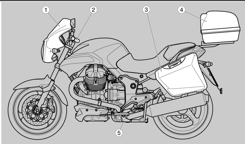
07_01
Indices accessories (07_01)
Están disponible los siguientes accesos:
- cupula levantada
- calefacción de los puños
- bolas laterales
- maletero
- caballete central
- antirrobo electrónico
Accessories index (07_01)
The following accessories are available:
- Top fairing extension
- Heated handlebars
- side panniers
- Glovebox
-
Centre stand
-
Electronic anti-theft device
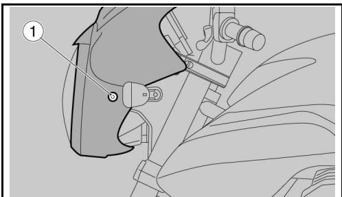
07_02
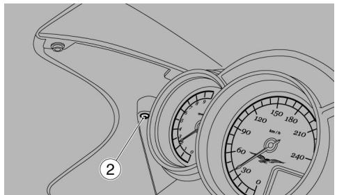
07_03
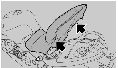
07_04
Carenados (07_02, 07_03, 07_04)
EXTRACCION DEL GRUPO OPTICO DELANTERO
Desatornillar y quitar los dos tornillos laterales (1) de ambos lados.
Desatornillar y quitar los dos tornillos (2) del tablero, a también lados.

Sostener el grupo optico delantero al no estar sujeto a las fijaciones.
En la parte trasera y elazo derecho:
- desconectar el cable acelerador.
- desconectar el mazo de cables del grupo optico delantero.
En la parte delantera:
Coger el faro delantero.
Coger la cupula.
EXTRACCION COLIN
Levantar el asiento y apoyarlo en el deposito combustible.
- Aflojar y quitar los dos tornillos.
Fairings (07_02, 07_03, 07_04)
REMOVAL OF FRONT HEADLIGHT ASSEMBLY
- Working from both sides, loosen and remove the two lateral screws (1).
- Working from both sides, loosen and remove the two screws (2) on the instrument panel.

Support the front headlight assembly then remove from its mountings.
Working from the left right-hand side:
- Disconnect the throttle cable.
- Disconnect the cable to the front headlight assembly.
Working from the front:
- Reconnect the front headlight.
- Reconnect the top fairing.
PASSenger SEAT COVER REMOVAL
- Raise the saddle and rest it on the fuel tank.
-
Loosen and remove the two screws.
-
Extraer en direccion hacia la cupula el colín.
Pull the passenger seat cover up towards the top fairing.
EL VALOR DE LA ASISTENCIA
Gracias a las continuasactualizaciones技术icas y alos programas de formacionespecifica sobre los productos Moto Guzzi,soleo mecanicos de la Red Oficial Moto Guzzi conocen profundamente este vehiculo y disponen del equipamento especial necessario para realizarcorrectamente de las intervencciones demantenimiento y reparacion.
La fiability del vehiculo también depende de las condidones mecánicas del本身就是. iE control antes de conducir, el mantenimiento regular y el uso exclusivo de Repuestos Originales Moto Guzzi son factores esencias!
Para Obtener información sobre el Concesionario Oficial y/o Centro de Asistencia más cercano, remitirse a las Páginas Amarillas oocular directamente en el mapa geografico de nuestro Sitio Oficial Internet:
www.motoguzzi.it
Sólo solicitaro Repuestos Originales Moto Guzzi se tendrá un producto estudiado y probado durante la fase de projeeto del vehiculo. Los Repuestos Originales Moto Guzzi está sometidos sistématicamente a procedimientos de control de calidad, para garantizar su confiabilidad y duración en el tiempo.
Las descripción e ilustraciones de la presente publicación no son contractuales; Por lo tanto, Moto Guzzi se reserva el Derecho de realizar, enequalquiermomento,las eventualesmodificacionesa los organospiezasouministrosde accesoriosque considereconvenientesy querespondanamayorasocualquier exigencia decaracterconstructivoocomercial,respetandoxmempreslascaracteristicasesenciasdel tipo descrito e ilustrado,ysin obligarseaactualizarinmediatamenteestapublicacion.
No todas las versiones de la presente publicación está disponible en todos los País. La disponibiliad de cada version se debe comprobar en la red oficial de vente Moto Guzzi.
Copyright 2006- Moto Guzzi. Todos los derechos reservados. Prohibida su reproduccion total o parcial. Moto Guzzi - After sales service.
THE VALUE OF SERVICE
Only the mechanics of the official Moto Guzzi Service Network know this vehicle well, thanks to constant technical professional development and Moto Guzzi-specific training programmes, and have the tools needed to carry out maintenance and repair operations correctly.
The reliability of the vehicle also depends on its mechanical conditions. Checking the vehicle before setting off, carrying out routine maintenance and
using only Moto Guzzi Original Spare parts is fundamental!
For information about the nearest Official Dealer and/or Service Centre, consult the Yellow Pages or search directly on the inset map in our Official Website:
www.motoguzzi.it
Only by purchasing Moto Guzzi Original Spare Parts will you get a product designed and tested during the bike's designing phase. Moto Guzzi Original Spare Parts are subject to systematic quality control procedures so that their reliability and performance over time is guaranteed.
The descriptions and illustrations given in this publication are not binding; While the basic features as described and illustrated in this manual remain unchanged, Moto Guzzi reserves the right, at any time and without being required to update this publication beforehand, to make any changes to components, parts or accessory supplies, which it deems necessary to improve the product or which are required for manufacturing or commercial reasons.
Not all versions shown in this publication are available in all Countries. The availability of individual versions should be checked with the official Moto Guzzi sales network.
Copyright 2006- Moto Guzzi. All rights reserved. Reproduction of this publication in whole or in part is prohibited. Moto Guzzi - After sales service.