
MA 635T - Microphone PEAVEY - Notice d'utilisation et mode d'emploi gratuit
Retrouvez gratuitement la notice de l'appareil MA 635T PEAVEY au format PDF.

| Type de produit | Amplificateur-mélangeur 7 canaux |
| Marque | PEAVEY |
| Modèle | MA 635T |
| Puissance de sortie | 35 watts |
| Réponse en fréquence | 20 Hz - 20 kHz (±1 dB direct, ±3 dB transformateur) |
| Distorsion harmonique totale (THD) | 0,02 % à 1 kHz, pleine puissance |
| Rapport signal/bruit | 95 dB (volume min), 79 dB (volume max), 100 dB (ampli seul) |
| Entrées | 6 ports pour modules enfichables, 1 entrée programme dédiée, pont entrée/sortie |
| Sorties | Directe 4 Ω, transformateur 8 Ω, 25 V, 70 V, sortie 600 Ω balancée |
| Contrôles | 7 réglages de gain, graves, aigus, contour, bypass EQ, master, coupe-bas, marche/arrêt |
| Indicateurs | LED d'alimentation, LED d'état bicolore (vert = signal, rouge = 2 dB de l'écrêtage) |
| Protection | Limitation de courant interne, relais SPS, fusibles (1 externe, 2 internes) |
| Alimentation | 120 V CA, 60 Hz, 75 W |
| Dimensions (H × L × P) | 13,2 cm × 43,2 cm × 32,1 cm |
| Couleur | Gris |
| Montage | Sur table ou en rack 19" |
| Caractéristiques spéciales | Compression SPS, filtre coupe-bas commutable, modules enfichables optionnels |
| Accessoires fournis | Cordon d'alimentation, fusible de rechange |
| Entretien et nettoyage | Nettoyer avec un chiffon humide ; ne pas utiliser de solvants. Débrancher avant nettoyage. |
| Sécurité | Ne pas ouvrir l'appareil ; risque de choc électrique. Confier toute réparation à un technicien qualifié. |
| Garantie | 1 an (pièces et main-d'œuvre) aux États-Unis. Ne couvre pas les dommages d'installation ou usage abusif. |
FOIRE AUX QUESTIONS - MA 635T PEAVEY
Questions des utilisateurs sur MA 635T PEAVEY
0 question sur cet appareil. Repondez a celles que vous connaissez ou posez la votre.
Poser une nouvelle question sur cet appareil
Téléchargez la notice de votre Microphone au format PDF gratuitement ! Retrouvez votre notice MA 635T - PEAVEY et reprennez votre appareil électronique en main. Sur cette page sont publiés tous les documents nécessaires à l'utilisation de votre appareil MA 635T de la marque PEAVEY.
MODE D'EMPLOI MA 635T PEAVEY
OPERATING INSTRUCTIONS

Intended to alert the user to the presence of uninsulated "dangerous voltage" within the product's enclosure that may be of sufficient magnitude to constitute a risk of electric shock to persons.

Intended to alert the user to the presence of important operating and maintenance (servicing) instructions in the literature accompanying the product.
CAUTION: Risks of electrical shock - DO NOT OPEN
CAUTION: To reduce the risk of electric shock, do not remove cover. No user serviceable parts inside. Refer Servicing to qualified service personnel.
MA 635T
Mixer Amplifier
FEATURES:
- 7 channel mixer/power amplifier system
20 - 20 kHz frequency response - Bridging input/output
Dedicated program input - Contour switch (special equalization)
- Bass and treble controls
- Preamp output/power amp input patch capability
- Short circuit and thermal protection
- SPS^TM compression circuitry
- Built-in low cut filter (switchable from rear panel)
- Plug in module capability
Output impedance variations: 4 ohm, 8 ohm, 25V, and 70V - Rack-mountable or stand alone package
- 600 balanced output
General Description
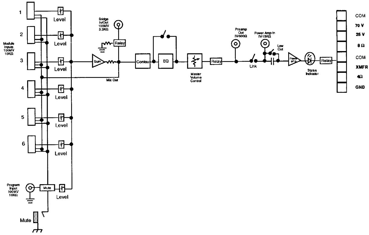
The Architectural Acoustics MA^TM 635T is a high quality mixer amplifier with seven separate input channels. Each channel provides a level control and the master output section features bass and treble EQ controls (defeatable), and special equalization contour.
The MA 635T provides unmatched application flexibility with an array of optional plug-in modules, allowing each system to be tailor-made for specialized installations. Input modules may be loaded in as required for varying sound reinforcement applications, number of input channels, special functions, etc.
The program input includes its own level control and is totally separate from the other six channels. External signals may be patched in at this point as a system auxiliary input or the seventh input channel. Signals appearing at this input are routed directly to the master summing amplifier stage and are mixed with signals from the other six channels. Systems requiring a single input may use the program
input and the purchase of an input module is not necessary. The program level control regulates the level of this input and the signal is routed through the system bass and treble controls.
The power section delivers 35 watts and includes built-in SPS^TM compression which allows the MA 635T to produce full power capability without audible power amp clipping. A broad load impedance range is provided and twenty-five and seventy volt line outputs are standard equipment. The MA 635T is packaged as a stand-alone unit but will also rack-mount into a standard 19" rack.
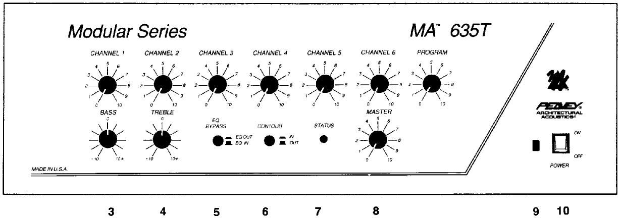
1. Channel Level Control
Controls the signal level at the channel input
2. Program Level Control
Controls the signal level at the program input.
3. Low EQ Control (Bass)
Active equalization control that adjusts the low frequency response. Clockwise rotation boosts lows while counterclockwise rotation provides a cut (reduction) of the low frequencies (± 10~dB)
4. High EQ Control (Treble)
Active equalization control that adjusts the high frequency response. Clockwise rotation boosts highs while counterclockwise rotation provides a cut (reduction) of the high frequencies (± 10~dB)
5. EQ Bypass
The "in" position of this switch bypasses bass and treble equalization. The "out" position allows operation of the equalization.
6. Contour Switch
The "in" position of this switch provides 6 dB boost at 100Hz and 6 dB boost at 10kHz . The "out" position removes boost from the system.
7. Status LED
Indicates output level from the master mixing stage. Bi-color illumination capability indicates signal activity (green) and 2 dB below clipping (red).
9. Power On LED
Indicates when AC power is being supplied to the unit.
10. Power Switch
Depress to "on" position to turn on.
8. Master
Controls the overall volume level of the system.
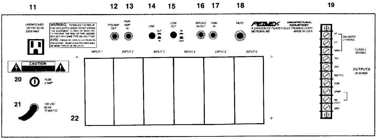
11. AC Outlet (Unswitched)
Provides AC power for auxiliary equipment with power consumption 300 watts maximum.
12. Preamp Out
Provides output signal to outboard gear for signal processing. Compressors, limiters, equalizers, etc., may be patched into the loop from this point. Signal from output of signal processor should return to power amp input. The "link" switch should be in the "in" position for this operation.
13. Power Amp Input
Provides access directly to the power amp. When using this input the "link" switch should be in the "in" position.
14. Link Switch
Breaks the signal flow routing from the preamp to the power amp when the link switch is in the "in" position, allowing external signals to be patched in at this point.
15. Low Cut Switch
Provides a 6 dB/octave low frequency roll-off at 60 Hz. The "in" position activates the low cut. The "out" position defeats the low cut.
16. Bridge In/Out
Provides output signal that is independent of the Master level control, Bass and Treble controls. It also may be used as a mixing output point when the similar terminal of another amplifier is connected to this terminal. A separate tape recording output may be taken from this point without interaction of EQ and master level control.
17. Program In
Accepts signals from other sources such as another mixer or mixer amplifier. Signal level at this input is controlled by the Program level control and is fed to the Master output. The program in may be regarded as channel "seven" without plug-in module capability.
NOTE: This input is muted whenever the mute line is grounded.
18. Mute
Plug-in modules are available with muting function. The mute line may be activated with an external switch at this point.
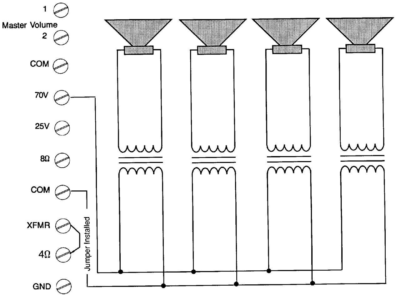
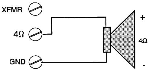
19. Outputs
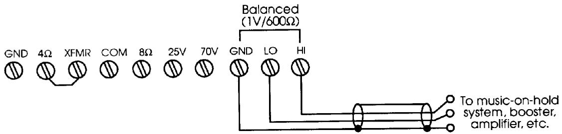
A direct output, as well as several transformer outputs, are provided to allow the proper interface between the amplifier and the speaker system. The direct output allows direct connection to a 4 ohm speaker system. To use this output, disconnect the jumper between the 4 ohm terminal and the XFMR terminal. Connect the speaker (or speakers) from the GND terminal to the 4 ohm terminal. 8 ohm, 25 volt, and 70 volt outputs are also provided. To used these outputs, the jumper between 4 ohm and XFMR must be installed. For 8 ohm speaker systems, connect between the COM terminal and the 8 ohm output. 25V and 70V outputs are also provided for "constant voltage" speaker distribution systems. The 25V output connection is between the COM terminal and the 25V terminal and the 70V output is between the COM terminal and the 70V terminal. The MA 635T also features a balanced, transformer isolated line level output. This output is provided for direct con
rection to "music on hold" systems, booster power amplifiers, etc. The balanced output is designed to deliver 1V RMS into a 600 ohm load.
20. Fuse
Replace with the same size and rating.
21. Power Cord
Connect to 120V AC power source.
22. Module Input Ports
Accepts plug-in modules for all six channels. Input modules are optional and should be selected by installation requirements.
NOTE: All modules will function in any of the six ports.
SPECIFICATIONS
Output Power:
35 watts
Power Bandwidth:
Direct: 20 - 20K < 0.5% THD
XFMR: 50-20K < 0.5% THD
Frequency Response:
Direct: 20-20K ±1.0 dB
XFMR:20-20K ±3 dB
THD:
0.02% at 1 kHz rated power
Output Regulation:
Direct: < 0.5 dB
XFMR: <1.0 dB
S/N Ratio:
Master Volume Min: 95 dB
Master Volume Max: 79 dB
Power Amp Only: 100 dB
Tone Controls:
Bass: ±10 dB @ 100 Hz
Treble: ±10 dB @ 10 kHz
Contour:
+6dB@100Hz
+6dB@10kHz
Inputs:
Six input ports, one dedicated program input bridge in/out
Input Sensitivity:
Ports 1-6 and PGM: 100mV @ 10K ohms
Bridge in/out: 100mV / 3.3K ohms
Preamp Out/Power Amp In:
1.0 V @ 600 ohms/1.0 V @ 15K ohms
Outputs:
Direct Out: 4 ohms
XFMR: 8 ohms, 25 volts, 70 volts (balanced)
Controls:
7 input gain controls, 1 bass control, 1 treble control, 1 contour switch, 1 master gain control, 1 power switch, 1 EQ defeat switch, 1 link switch, 1 low-cut switch
Indicators:
Power LED, Bi-color (green/red) status LED
Protection:
Internal current limiting, SPS (speaker protection) output relays, 1 line fuse (external), and 2 internal fuses
Connectors:
Preamp Out, Power Amp In, PGM input, bridge in/out, RCA phono jack, Ports 1-6: Card edge connector, Outputs: Screw terminals, Mute: 14 jack, AC SJT, 3 prong
Power Consumption:
AC 120 volts, 60 Hz, 75 watts
Dimensions:
5.20" (H) × 17.00" (W) 12.625" (D)
Color:
Gray
Other Features:
600 ohm output
Output disconnected for 4 seconds after power on.
70V "Constant Voltage" Distribution System
1 V Balanced Output Connectors
Direct output to 4 Speaker

Master Volume


BLOCK DIAGRAM
DANGER
EXPOSURE TO EXTREMELY HIGH NOISE LEVELS MAY CAUSE A PERMANENT HEARING LOSS. INDIVIDUALS VARY CONSIDERABLY IN SUSCEPTIBILITY TO NOISE INDUCED HEARING LOSS, BUT NEARLY
EVERYONE WILL SLOW SOME HEARING IF EXPOSED TO SUFFICIENTLY INTEASE NOISE FOR A SUPPLEMENT TIME. THE U.S. GOVERNMENT'S OCCUPATIONAL SAFETY AND HEALTH ADMINISTRATION (IOSHA) HAS SPECIFIED THE FOLLOWING PERMISSIBLE NOISE LEVEL EXPOSURES:
DILATION PER BAY IN HOIPRE
SOUND LEVEL GBA SLOW RESPONSE
1
。
92
6
06
A7
3
100
2
100
1%
12
1
163
%
10
ACCORDING TO OSHA ANY EXPOSURE IN EXCESS OF THE ABOVE PERMISSIBLE LIMITS COULD RESULT IN SOME HEARING LOSS.
EAR PLUGS OR PROECTORS IN THE EAR CANCER OR OVER THE BARS MUST BE LIKE WHERE OPERATING THIS AMPLIFICATION SYSTEM IN ORDER TO PREVENT A PRIMINANT HEARSOUND ISS IF EXPOSURE IS IN EXCESS OF THE LIMITS AS SET PORTH ABRE TO INSURBE AGAINST POTENTIALLY FAMORAL EXPENSES TO HIGH SOUND PRESSURE LEVELS. IT IS COMMENDEED THAT ALL PERSONNEL EXPOSED TO EQUIPMENT CAPABILIT* OF PROUCING HIGH SOUND PRESSURE LEVELS SUCH AS THIS AMPLIFICATION SYSTEM BE PROXPECTED BY HEARSOUND PROPERTIES WHILE THEREINITIS
T 1
- Board safety and training requirements
this
2. All safety and spacing instructions should be re
for future reference
3. Obey all cautions in the operating instructions and on the
back of the unit.
4. All operating instructions should be followed.
5. This product should not be used near water, i.e., a
bathpub sink swimming pool wet basement, etc.
5. This product should be located so that its position does
not interfere with its proper ventilation. It should not be placed flat against a wall or placed in a built-in enclosure (see Figure 1).
7 This product should not be placed near a source of heat such as a stove, radiator or another heat producing device.
- Connect ong power supply of type marked
- "Need to look at the ground pin down/upper supply base."
- "Please check that you have all pins for our free booklet - Shock Hazard and Grounding."
10 Power supply cords should always be handled carefully. Never walk or place equipment on power supply cords. Periodically check cords for cuts or signs of stress, especially at the plug and the point where the cord exits the unit.
-
The power supply cord should be unplugged when the
unit is to be unused for long periods of time.
12 If this product is to be mounted in an equipment rack, rear support should be provided
-
Whole parts can be cleaned with a damp box. The epoxy should be cleaned by some units before a clean-up of the damp
H
-
Care should be taken so that objects do not fall and liquids are not spilled into the unit through the ventilation system.
- This unit should be checked by a qualified service technician if:
A. The power supply cord or plug has been damaged.
B. Anything has fallen or been spilled into the unit
D. The unit has been dropped or the enclosure damaged.
- The following are not available in this equipment:
- The data should not attempt to service the equipment. All service work should be done by a qualified service professional.
10 Power supply cords should always be handled carefully. Never walk or place equipment on power supply cords. Periodically check cords for cuts or signs of stress, especially at the plug and the point where the cord exits the unit.
The power supply cord should be unplugged when the
unit is to be unused for long periods of time.
12 If this product is to be mounted in an equipment rack, rear support should be provided
Whole parts can be cleaned with a damp box. The epoxy should be cleaned by some units before a clean-up of the damp
H
Care should be taken so that objects do not fall and liquids are not spilled into the unit through the ventilation system.
A. The power supply cord or plug has been damaged.
B. Anything has fallen or been spilled into the unit
D. The unit has been dropped or the enclosure damaged.
CON
70V
25V
80
COM
YME
40
GND
LIMITED WARRANTY
Peavey Electronics Corporation warrants to the original purchaser of this new Architectural Acoustics product that it is free from defects in material and workmanship. If within one (1) year from date of purchase a properly installed product proves to be defective and Peavey is notified, Peavey will repair or replace it at no charge. (Note: Batteries and patch cords not covered.) "Original purchaser" means the customer for whom the product is originally installed.
Damage resulting from improper installation, interconnection of a unit or system of another manufacturer, accident or unreasonable use, neglect or any other cause not arising from defects in material and workmanship is not covered by this warranty. The warranty is valid only as to products purchased and installed in the United States.
THIS LIMITED WARRANTY IS IN LIEU OF ANY AND ALL WARRANTYES, EXPRESSED OR IMPLIED, INCLUDING THE IMPLIED WARRANTYES OF MERCHANTABILITY AND FITNESS FOR A PARTICULAR USE. UNDER NO CIRCUMSTANCES WILL PEAVEY BE LIABLE FOR ANY LOST PROFITS, LOST SAVINGS, INCIDENTIAL DAMAGES OR CONSEQUENTIAL DAMAGES ASING OUT OF THE USE OR INABILITY TO USE THE PRODUCT, EVEN IF PEAVEY HAS BEEN ADVISED OF THE POSSIBILITY OF SUCH DAMAGE. THIS LIMITED WARRANTY IS THE ONLY EXPRESSD WARRANTY ON THIS PRODUCT, AND NO OTHER STATEMENT, REPRESENTATION, WARRANTY, OR AGREEMENT BY ANY PERSON SHALL BE VALID OR BINDING UPON PEAVEY.
Peavey's liability to the original purchaser for damages for any cause whatsoever and regardless of the form of action, is limited to the actual damages up to the greater of Five Hundred Dollars ((500) or an amount equal to the purchase price of the product that caused the damage or that is the subject of or is directly related to the cause of action. This limitation of liability will not apply to claims for personal injury or damage to real property or tangible personal property allegedly caused by Peavey's negligence. For information on service under this warranty, call a Peavey customer service representative at (601) 483-5376.

Features and specifications subject to change without notice.
A Division of Peavey Electronics Corporation
711 A Street, P. O. Box 2898, Meridian, MS 39302-2898 / (601) 483-5376 / Telex 504115 / Fax (601) 484-4278
Printed in U.S.A. 8/91


- OPERATING INSTRUCTIONS
- FEATURES:
- General Description
- Channel Level Control
- Program Level Control
- Low EQ Control (Bass)
- High EQ Control (Treble)
- EQ Bypass
- Contour Switch
- Status LED
- Power On LED
- Power Switch
- Master
- AC Outlet (Unswitched)
- Preamp Out
- Power Amp Input
- Link Switch
- Low Cut Switch
- Bridge In/Out
- Program In
- Mute
- Outputs
- Fuse
- Power Cord
- Module Input Ports
- SPECIFICATIONS
- Output Power:
- Power Bandwidth:
- Frequency Response:
- THD:
- Output Regulation:
- S/N Ratio:
- Tone Controls:
- Contour:
- Inputs:
- Input Sensitivity:
- Preamp Out/Power Amp In:
- Outputs:
- Controls:
- Indicators:
- Protection:
- Connectors:
- Power Consumption:
- Dimensions:
- Color:
- Other Features:
- Direct output to 4 Speaker
- Master Volume
- LIMITED WARRANTY
Marque : PEAVEY
Modèle : MA 635T
Catégorie : Microphone