
A4E - Interrupteur industriel OMRON - Notice d'utilisation et mode d'emploi gratuit
Retrouvez gratuitement la notice de l'appareil A4E OMRON au format PDF.
| Type de produit | Interrupteur industriel à 3 positions |
| Marque | OMRON |
| Modèle | A4E |
| Tension d'isolement nominale | 250 V |
| Courant nominal | 2,5 A |
| Charge nominale | 24 VCC, 300 mA (inductif) / 125 VCA, 1 A (résistif) |
| Charge minimale applicable | 24 VCC, 4 mA |
| Nombre de contacts | 2 (modèle B) ou 4 (modèle C) |
| Forme des contacts (type 2 contacts) | 2NO (sortie d'activation) |
| Forme des contacts (type 4 contacts) | 2NO (activation) + 1NF (relâchement) + 1NF (préhension) |
| Schéma de fonctionnement | OFF-ON-OFF en actionnement, OFF-OFF momentané en réinitialisation |
| Température ambiante | -10°C à 55°C (sans givre) |
| Humidité ambiante | 35% à 85% (sans condensation) |
| Température de stockage | -25°C à 65°C |
| Résistance d'isolement | 100 MΩ min (à 500 VCC) |
| Résistance de contact | 100 mΩ max (valeur initiale) |
| Endurance mécanique | 1 000 000 opérations (OFF-ON) / 100 000 opérations (OFF-ON-OFF) |
| Endurance électrique | 100 000 opérations min |
| Degré de protection | IP65 (modèles avec joint en caoutchouc) |
| Force d'activation | 7 N max (sans joint) / 14 N max (avec joint) |
| Force de maintien | Environ 5,5 N (sans joint) / 8 N (avec joint) |
| Force de préhension | 35 N max (sans joint) / 40 N max (avec joint) |
| Course d'activation | 3,2 mm max (sans joint) / 3,4 mm max (avec joint) |
| Course maximale | Environ 6,5 mm (sans joint) / 6,7 mm (avec joint) |
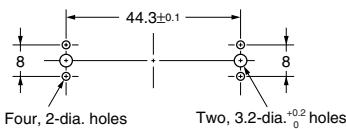
| Type de borne | Bornes à souder |
| Section de fil recommandée | 0,5 à 0,75 mm² |
| Normes approuvées | EN 60947-5-1, UL 508, CSA C22.2 No. 14 |
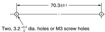
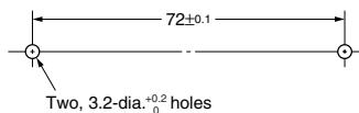
| Fixation | Vis M3 avec rondelles, couple 0,39-0,59 Nm |
| Entretien et nettoyage | Nettoyer avec un chiffon sec, éviter les solvants |
| Pièces détachées | Joint en caoutchouc, supports de montage (horizontal, vertical, sans support) |
FOIRE AUX QUESTIONS - A4E OMRON
Questions des utilisateurs sur A4E OMRON
0 question sur cet appareil. Repondez a celles que vous connaissez ou posez la votre.
Poser une nouvelle question sur cet appareil
Téléchargez la notice de votre Interrupteur industriel au format PDF gratuitement ! Retrouvez votre notice A4E - OMRON et reprennez votre appareil électronique en main. Sur cette page sont publiés tous les documents nécessaires à l'utilisation de votre appareil A4E de la marque OMRON.
MODE D'EMPLOI A4E OMRON
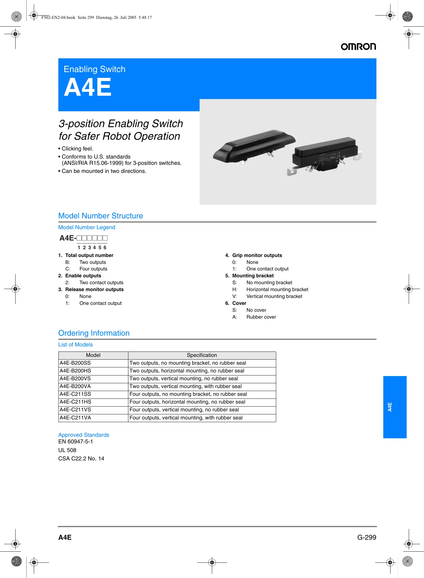
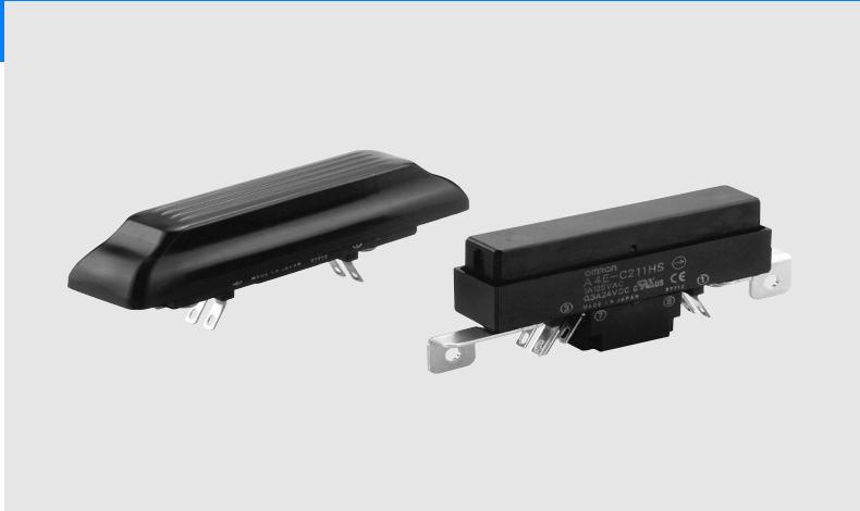
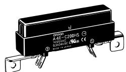
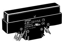
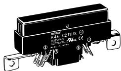
Enabling Switch
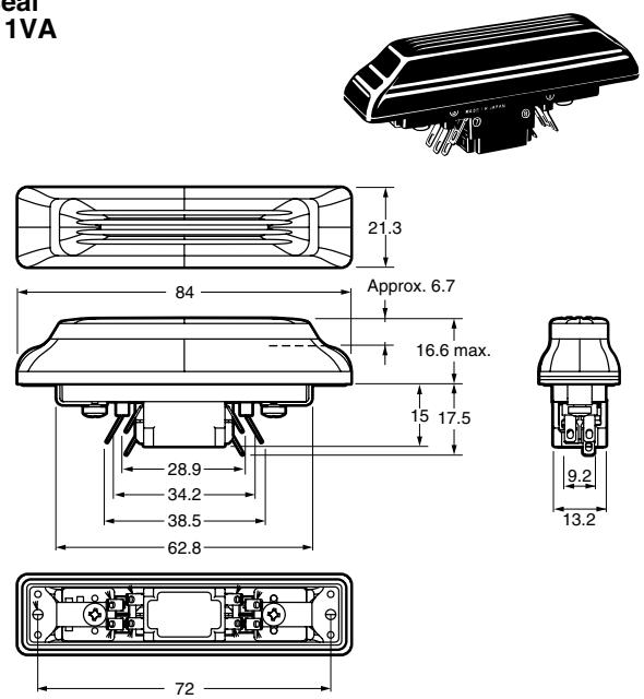
A4E
3-position Enabling Switch for Safer Robot Operation
- Clicking feel.
- Conforms to U.S. standards (ANSI/RIA R15.06-1999) for 3-position switches.
- Can be mounted in two directions.
Model Number Structure
Model Number Legend

123456
1. Total output number
B: Two outputs
C: Four outputs
2. Enable outputs
2: Two contact outputs
3. Release monitor outputs
0: None
1: One contact output
4. Grip monitor outputs
0: None
1: One contact output
5. Mounting bracket
S: No mounting bracket
H: Horizontal mounting bracket
V: Vertical mounting bracket
6. Cover
S: No cover
A: Rubber cover
Ordering Information
List of Models
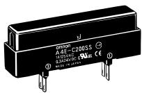
| Model | Specification |
| A4E-B200SS | Two outputs, no mounting bracket, no rubber seal |
| A4E-B200HS | Two outputs, horizontal mounting, no rubber seal |
| A4E-B200VS | Two outputs, vertical mounting, no rubber seal |
| A4E-B200VA | Two outputs, vertical mounting, with rubber seal |
| A4E-C211SS | Four outputs, no mounting bracket, no rubber seal |
| A4E-C211HS | Four outputs, horizontal mounting, no rubber seal |
| A4E-C211VS | Four outputs, vertical mounting, no rubber seal |
| A4E-C211VA | Four outputs, vertical mounting, with rubber seal |
Approved Standards
EN 60947-5-1
UL 508
CSA C22.2 No. 14
Specifications
Ratings
| Rated insulation voltage | 250 V |
| Rated ON current | 2.5 A |
| Rated load | 24 VDC, 300 mA (inductive load) 125 VAC, 1 A (resistive load) |
| Minimum applicable load | 24 VDC, 4 mA |
| Impulse withstand voltage | 4.0 kV between terminals of different polarity, 2.5 kV between terminals of same polarity |
| Ambient temperature | -10°C to 55°C (with no icing) |
| Ambient humidity | 35% to 85% (with no condensation) |
| Storage temperature | -25°C to 65°C |
Characteristics
| Insulation resistance | 100 M min. (at 500 VDC) |
| Contact resistance | 100 m max. (initial value) |
| Vibration resistance | 10 to 55 Hz, 0.75-mm single amplitude min. |
| Shock resistance | 150 m/s2 |
| Mechanical durability | OFF-ON: 1,000,000 operations min. OFF-ON-OFF (direct opening): 100,000 operations min. |
| Electrical durability | 100,000 operations min. |
| Degree of protection | IP65 (rubber seal type only) |
Structure
| Contact form | 4-contact type:2NO (enable output) 1NC (release output) 1NC (grip output) Direct opening for all contacts (See note) |
| 2-contact type:2NO (enable output) Direct opening for all contacts (See note) | |
| Operating pattern | During operation: OFF-ON-OFF During reset: OFF-OFF momentary 3-position operation |
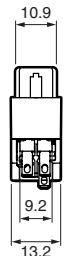
| Terminal shape | Solder terminals |
Note: Direct opening only during grip.
Contact form

Note: SW3 and SW4 are for 4-contact types only.
Operating Characteristics

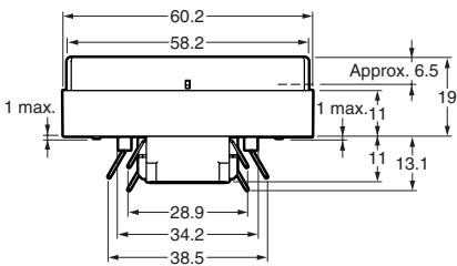
Operating stroke
| Symbol | Name | A4E-B200□S | A4E-B200VA (See note.) | A4E-C211□S | A4E-C211VA (See note.) |
| PT1 | Release output (ON) | --- | --- | 1 mm max. | 1.2 mm max. |
| PT2 | Enable output (ON) | 3.2 mm max. | 3.4 mm max. | 3.2 mm max. | 3.4 mm max. |
| TT1 | Max. enable holding position | Approx. 4 mm | Approx. 4.2 mm | Approx. 4 mm | Approx. 4.2 mm |
| PT3 | Enable direct opening position | 5.4 mm max. | 5.6 mm max. | 5.4 mm max. | 5.6 mm max. |
| PT4 | Grip output (ON) | --- | --- | 5.4 mm min. | 5.4 mm min. |
| TT2 | Max. stroke | Approx. 6.5 mm | Approx. 6.7 mm | Approx. 6.5 mm | Approx. 6.7 mm |
Note:Not including the rise of the rubber cover (0.5 mm max.).
Operating force (reference values)
| Symbol | Name | A4E-B200□S | A4E-B200VA | A4E-C211□S | A4E-C211VA |
| OF1 | Enable operating force | 7 N max. | 14 N max. | 7 N max. | 14 N max. |
| HF (See note) | Enable holding force | Approx. 5.5 N | Approx. 8 N | Approx. 5.5 N | Approx. 8 N |
| OF2 | Grip operating force | 35 N max. | 40 N max. | 35 N max. | 40 N max. |
Note: HF indicates "holding force".
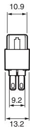
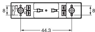
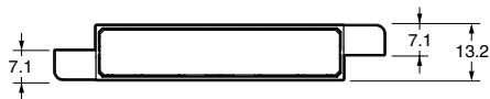
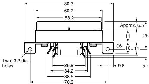
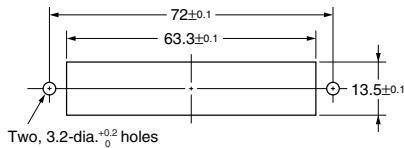
Note: All units are in millimeters unless otherwise indicated.
2-contact type
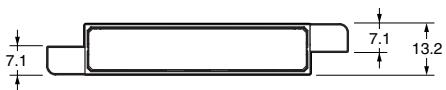
No mounting bracket A4E-B200SS
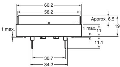
Horizontal mounting A4E-B200HS
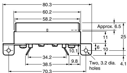
4-contact type
No mounting bracket A4E-C211SS

Horizontal mounting A4E-C211HS
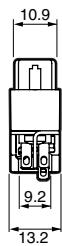
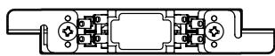
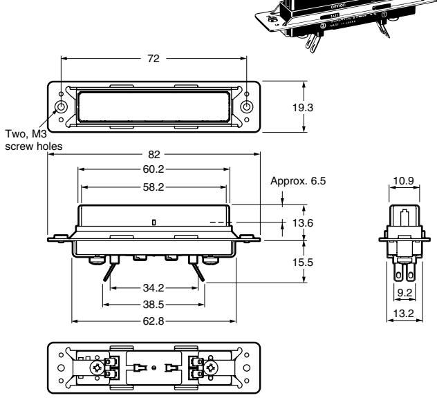
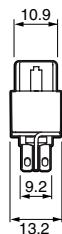
Vertical mounting A4E-B200VS
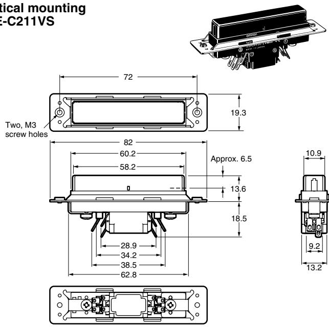
Vertical mounting A4E-C211VS
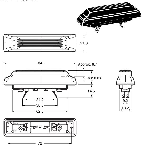
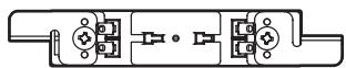
Vertical mounting with rubber seal A4E-B200VA
Vertical mounting with rubber seal A4E-C211VA
WARNING
Do not wire the Switch or touch any terminal of the Switch while power is being supplied. Doing so may result in electric shock.
WARNING
Always use the Switch in a system that is operated directly by hand. Do not operate the Switch with a mechanical actuator. Insufficient Switch strength may result in damage to the Switch, electric shock, or fire.
CAUTION
Design a safe system for using the Switch, based on a risk assessment that takes into account all reasonably foreseeable malfunctions.
CAUTION
Determine the Switch mounting direction and structural design only after thorough risk assessment. For example, in a structure where the Switch protrudes from the pendant perimeter, the weight of the pendant itself could place the Switch into the enable condition and operate the machine. Likewise, in a buried structure where the Switch lies below the surface of the pendant, the Switch may not enter the grip condition when pressed and thus fail to stop the machine.
CAUTION
Configure the system so that the machine operates only when the Switch is in the enable position.
Correct Use
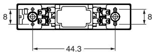
Mounting
Use M3 screws and flat washers or spring washers to mount the Switch securely. Use a tightening torque of 0.39 to 0.59 Nm.
No-mounting-bracket type
Horizontal mounting type
Vertical mounting type
Vertical mounting type with rubber seal
Wiring
- Use an appropriate wire size (0.5 to 0.75mm^2 ) for the applied voltage and carry current.
- Do not use a #110 tab receptacle.
- Wire according to the terminal numbers. Mistaken wiring may damage the Switch and result in fire.
- Wire according to the terminal arrangement.
- Use good-quality 6:4 (tin:lead) solder.
- Use a resin flux cored solder.
- Do not use a liquid or chlorine type flux.
- Perform soldering within 3 s using a 30-W max. soldering iron (temperature at the tip of the soldering iron: 350^ max.). Insulate with an insulation tube.
- Do not move the terminal for at least one minute after soldering.
- Do not apply a force that would deform the terminal when wiring.
Operating Environment
Prior to using the Switch in places that are subject to contact by oil spray or chemicals, check the effect of those substances on the Switch.
Some types of oil spray and chemicals will degrade the sealing capability, which may result in faulty contact, defective insulation, ground fault, or burning damage.
Improper Operating Environment
- Do not use the Switch in places that are subject to sudden temperature change.
- Do not use the Switch in places that are subject to high temperatures and condensation.
- Do not use the Switch in places that are subject to strong vibration.
- Do not use the Switch in places that are subject to direct contact with machine filings or dust.
Storage
- Do not store the Switch in places with hydrogen sulfide or other corrosive gas or sea breeze.
- Do not store the Switch in places where the level of dust is high enough to be visible.
- Do not store the Switch in direct sunlight.
- Do not impose excessive force on the Switch during storage. Otherwise, the Switch may deform.
Handling
- Do not drop the Switch. Otherwise, the Switch may malfunction.
- Do not apply strong vibration or shock to the Switch. Otherwise, the Switch may malfunction or be damaged.
Do not contact the Switch with sharp objects. Otherwise, the Switch may be scratched. Scratches on the operating portion of the Switch may result in problems both in appearance and operation.
ALL DIMENSIONS SHOWN ARE IN MILLIMETERS.
To convert millimeters into inches, multiply by 0.03937. To convert grams into ounces, multiply by 0.03527.