
IIIA - Appareil photo LEICA - Notice d'utilisation et mode d'emploi gratuit
Retrouvez gratuitement la notice de l'appareil IIIA LEICA au format PDF.

| Intitulé | Description |
|---|---|
| Type de produit | Appareil photo télémétrique 35 mm |
| Caractéristiques techniques principales | Format 35 mm, obturateur à rideau en tissu, plage de vitesse d'obturation de 1/20 à 1/500 s, mode de mesure de la lumière externe |
| Alimentation électrique | Non applicable (fonctionne sans batterie) |
| Dimensions approximatives | 140 x 80 x 36 mm |
| Poids | Environ 600 g |
| Compatibilités | Objectifs à monture Leica L |
| Type de batterie | Non applicable |
| Tension | Non applicable |
| Puissance | Non applicable |
| Fonctions principales | Photographie argentique, mise au point manuelle, exposition manuelle |
| Entretien et nettoyage | Nettoyer le boîtier avec un chiffon doux, éviter l'humidité, faire vérifier le mécanisme par un professionnel si des problèmes surviennent |
| Pièces détachées et réparabilité | Réparabilité élevée, pièces détachées disponibles chez les revendeurs spécialisés |
| Informations générales utiles | Appareil apprécié pour sa robustesse et sa qualité d'image, idéal pour les photographes expérimentés et les amateurs de photographie argentique |
FOIRE AUX QUESTIONS - IIIA LEICA
Questions des utilisateurs sur IIIA LEICA
0 question sur cet appareil. Repondez a celles que vous connaissez ou posez la votre.
Poser une nouvelle question sur cet appareil
Téléchargez la notice de votre Appareil photo au format PDF gratuitement ! Retrouvez votre notice IIIA - LEICA et reprennez votre appareil électronique en main. Sur cette page sont publiés tous les documents nécessaires à l'utilisation de votre appareil IIIA de la marque LEICA.
MODE D'EMPLOI IIIA LEICA
DIRECTIONS
Leica Camera
ERNST LEITZ, WETZLAR AND LONDON
Contents
A. Leitz Leica Camera with focal plane shutter: Page
- External parts of the Leica Camera 3
- Opening the camera 5
B. The Leica Spool Chamber Model B:
- Its components 6
- Loading of spool chamber Model B 8 (Daylight loading film spools)
- The Leica Film Cartridges of Agfa Gevaert Kodak Perutz 10
- Loading of film chamber Model B 12 (Darkroom loading film spools)
C. Loading the camera 15
D. Taking the photograph 19
E.Unloading of camera 19
F. The "Standard" Leica Camera 20
G. Some additional hints on the use of the Leica:
- Trimming Template 21
- Hand Film Winder. 23
3.MechanicalWinder. 24 - Winding of film in camera. 24
- Winding and setting focal plane shutter.. 25
- Release 26
- Rangefinder 27
8.Holding the Leica 28
9.Viewfinder 30
H. The Leica "250" 31
I. Accessories for single exposures:
- Special device for single exposures with dark slide and focusing screen 33
2.Single film holder 34
K. The interchangeable Leica lenses 36
- Elmar, Hektor, Summar, Thambar and Telyt 37-41
2.Helical mount and infinity catch. 42 - Automatic coupling 43
4.Iris diaphragm. 43 - Depth of focus collar 43
L. Accessories for the Leica Camera:
1.Angular Viewfinder 45
2.Universal Viewfinders 45-48
3. Frame Viewfinder 49
4. Reflecting Viewfinder 50
5. Slow-speed Attachment 51
6.Supplementary Front Lenses. 52
7. Yellow, green, red and U.V. protective filters 54-59
8. Lens hoods 60
9. Panoramic Tripod Head and Case Level 61
10. Ball-jointed Tripod Head. 63
11. Tripod head with press catch 63
12. Stereo Slider 63
Leica Camera Model IIIa
for single (still) pictures on standard cinematograph film strips
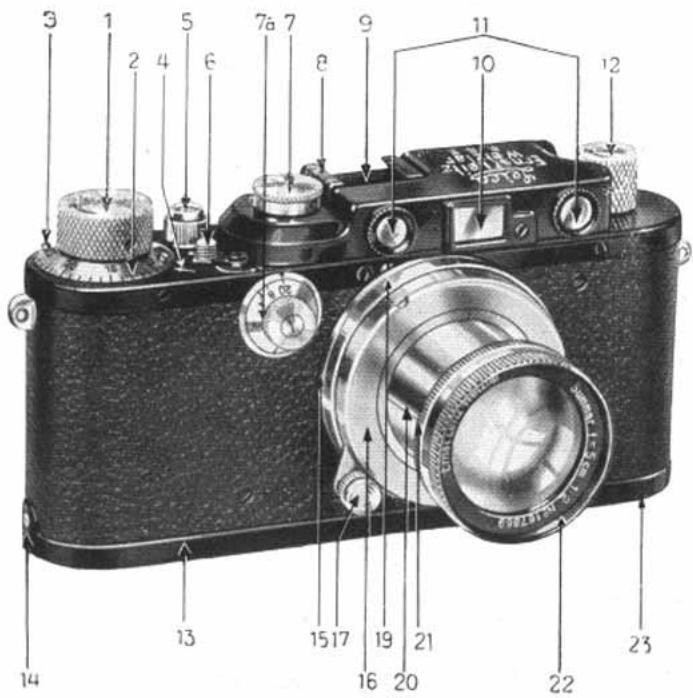
Fig. 1
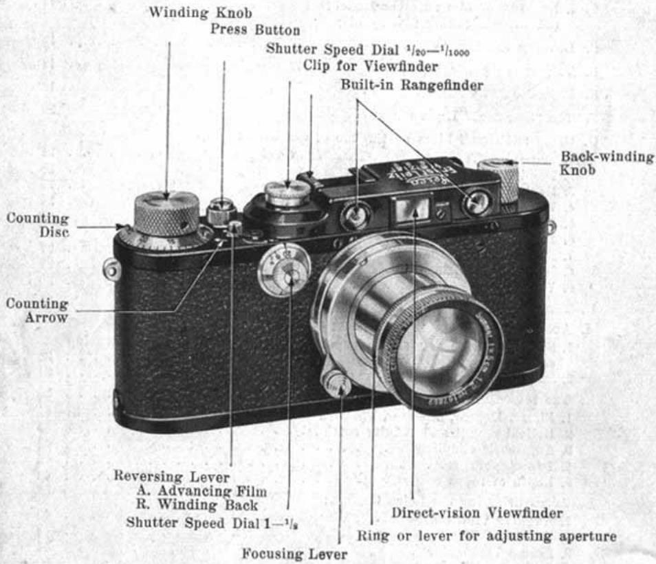
1. The external parts of the Leica Camera
- Winding knob for simultaneous winding of film and setting of shutter.
-
Counting disc, automatically recording the number of exposures.
-
One of the two lugs by means of which the counting disc is turned anti-clockwise and against the direction of the arrow on the winding knob for zero setting.
- Counting Arrow, indicating the number of photographs taken.
- Press Button, to which may be screwed a Wire Release (after the milled protective ring has been removed).
- Reversing Lever for engaging (towards A) and disengaging (towards R) the automatic coupling of film advance and shutter mechanism before and after exposures have been made (before re-winding film).
- Shutter-speed Dial, for adjustment of speed required (to be set after winding of shutter) - See (1).
7a. Adjusting dial for the slow instantaneous speeds from 1 - 1 / 8 sec. - Index Arrow, for figures of Speed Dial (7).
- Clip, to hold Universal View-finder, etc.
- View-finder showing size of image.
- The two Object Glasses of the Range Finder, the mechanism of which is interconnected with the focusing mount of the lens.
- Back-winding Knob (extensible) to wind the film back into spool chamber after exposure.
- Camera Lid.
- Pin over which the camera lid is hooked at one end. (See also 23.)
- Lens changing flange for interchange of Leica lenses of various focal lengths.
- Distance Scale. (Not visible.)
- Lens focusing lever with catch for infinity, actuating the adjustment of range finder and focusing of lens simultaneously (index not visible in illustration).
- Depth of focus collar. (Scale not visible, see Fig. 41.)
- Tubular Socket of Lens, to be pulled out for photographing, when the lens is locked in a bayonet catch by turning it to the right (clockwise).
- Ring or lever with index line for adjusting aperture.
- Front of lens mount.
- Swivel (not visible) for opening and closing camera lid (see Fig. 2).
2. Opening the Leica Camera
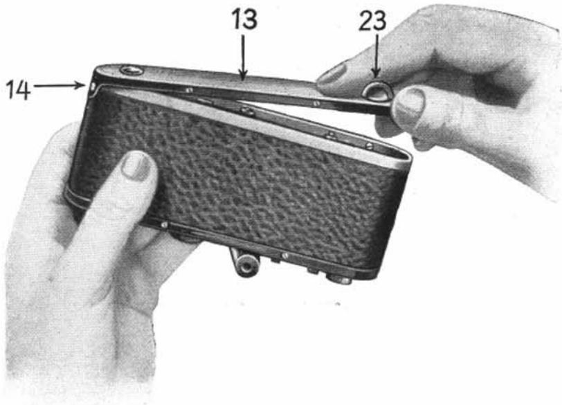
Fig. 2
Turn the camera upside down and open lid 13 by raising swivel 23 and turning same from "closed" to "open" as far as it will go. Lift lid and then unhook at pin 14.
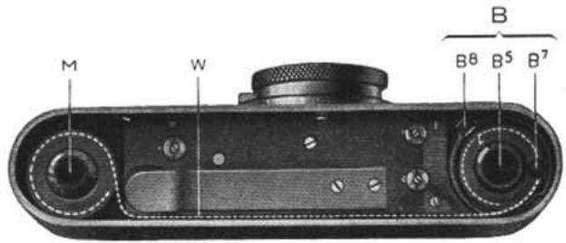
Fig. 3
The interior then presents the appearance as shown in Fig. 3. Now withdraw the spool chamber B by the milled knob
B. The Leica Spool Chamber Model B
1. Its Components
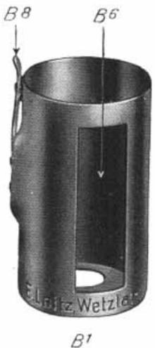
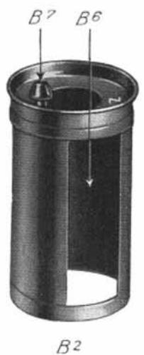
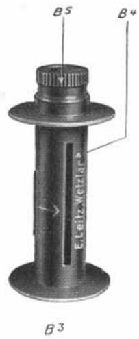
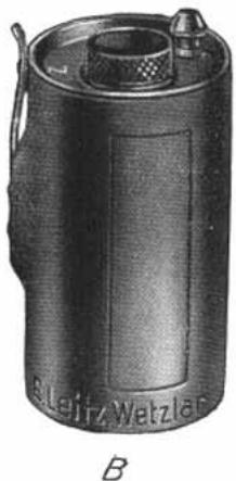
Fig. 4 and 5
B = Complete Spool Chamber Model B
B^l = Outer Shell
B^2 Inner Shell
B^3 = Centre Spool
B^4 = Slot of Centre Spool
B^5 = Milled Knob of Centre Spool
B^6 = Slots of Spool Chamber
B^7 = Knob of Spool Chamber
B^8 = Safety Spring
The Leica Chamber Model B is of cylindrical form and consists of three components: the Outer shell B^1 , the Inner shell B^2 , and the centre spool B^3 .
The guide-groove on the inner shell and the pin inside the outer shell (opposite the safety spring, which is not visible in illustration) make the opening and closing of the chamber mechanical.
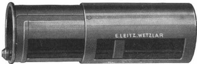
Fig. 6. Leica Spool Chamber Model B open
As will be seen in the illustration, Fig. 6, the guide-groove first runs along the inner shell and then terminates in a semicircle at the upper rim of the shell. The guide-pin of the outer shell then constrains the inner shell to be moved along the slot in the required manner, thus:
- Introduce the inner shell with spool in the outer shell until its rim comes to a stop, the slot openings being then one above the other;
- Turn inner shell to the left (anti-clockwise) up to the limit stop, when the safety spring will then engage.
Again, the chamber can only be opened by first slightly lifting the safety spring, turning the inner shell to the right (clockwise), and then withdrawing it, i.e. by going through the same process in exactly the reverse order. (See Fig. 7.)
2. Loading Spool Champer Model B by subdued daylight
(Daylight loading film spools)
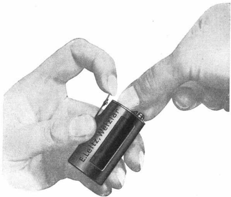
Fig. 7. How the spool chamber B should be opened
-
Open Spool Chamber. To this end release with the index finger of the left hand the safety spring B^s by pulling it backwards (Fig. 7) and turn the inner shell with the right hand at the knob towards the right (clockwise), to the end of the movement. Then withdraw inner shell.
-
Remove the centre spool from the inner shell and keep it as it is only required for darkroom loading.

Fig. 8
- Insert daylight loading film spool into the inner shell with the milled knob first, and so that the seal lies in the slot.
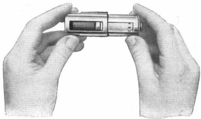
Fig. 9
- Put both together into the outer shell, the two slots superimposing; break seal and withdraw paper strip and the beginning of the film to about 2 inches through the open slot of the chamber.
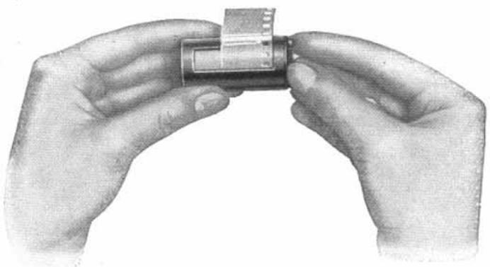
Fig. 10
- Close spool chamber by giving the inner shell half a turn to the left, when the safety spring will engage at the mark Z; now withdraw the paper strip only, holding the film so that it does not come out together with the paper.
- If the loaded chamber is not to be used in the camera immediately, it should be kept in the aluminium container so that it is not exposed to daylight too long. With highly sensitive Leica films the projecting beginning of the film conducts the light into the spool chamber and thus causes fogging. This is not the case with backed films or films having an intermediate layer against halo. For this reason we particularly commend these brands.
Daylight loading Leica films are supplied by Mimosa and Gevaert, each spool containing a film strip 5^1 / 4 ft. long, sufficient for 36 exposures of the Leica size 24× 36mm Re Agfa and Perutz Leica cartridges see below.
Loading of camera, exposures and unloading of camera, see pages 15-19.
3. The Leica cartridges
for daylight loading and unloading
The Leica spool chamber Model B may be loaded into the camera in daylight and may also be removed in daylight, but the film cannot be taken out of the spool chamber
in daylight, so that in special circumstances one may need a larger number of spool chambers in order to avoid unloading them in the darkroom.
In such cases, the Leica cartridges of Messrs. Agfa, Gevaert, Hauff, Kodak and Perutz provide a satisfactory solution. These firms supply their films in special Leica cartridges for daylight loading. The cartridge is used once only and is opened in the darkroom for developing the film.
The loading of the Leica cartridges into the camera, and also the unloading, is done in the same way as a loaded spool chamber Model B. For further details see pages 15-19.
Please note. Leica cameras which are not yet equipped with the lock V^2 (see Fig. 11) must have this part fitted if the Leica cartridges are to be used.
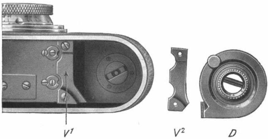
Fig. 11
To enable Leica cartridges to be used also in earlier models of the camera, the lock V^1 as shown in Fig. 11 must, by loosening the two screws which hold it, be exchanged for a new V^2 lock of somewhat different form. This is quite an easy matter. The new lock is supplied free of charge. After changing the lock, not only Leica cartridges, but also all other Leica spool chambers may be used in the camera.
4. Loading of Film Chamber Model B in the darkroom
(In this case darkroom loading film spools are used)
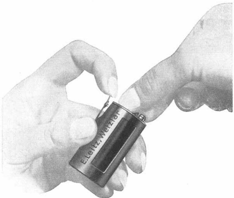
Fig. 12
How the spool chamber Model B should be opened
- Open spool chamber. To this end release with the index finger of the left hand the safety spring B^s by pulling it backwards (Fig.12) and turn the inner shell with the right hand at the knob towards the right (clockwise) to the end of the movement. Then withdraw inner shell.
- Remove the centre spool from the inner shell. Take the wrapping off the film.
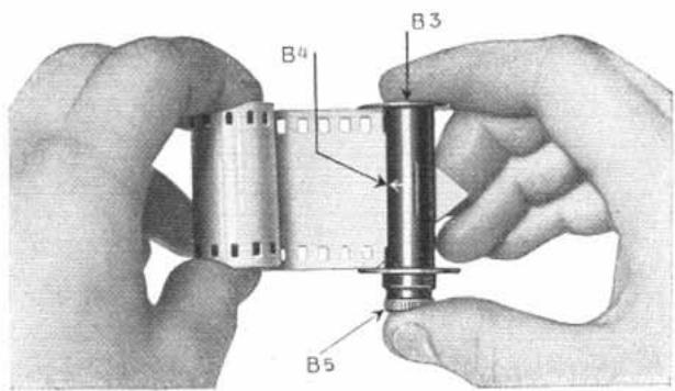
Fig. 13
- Thread the short tapered end of the film in the slot B^4 of the centre spool B^3 (emulsion side next to the arrow) in the direction of the arrow.
- Wind film on centre spool moderately tight, emulsion side inward, and if possible use hand film winder or mechanical winder. Take care that emulsion is not touched.
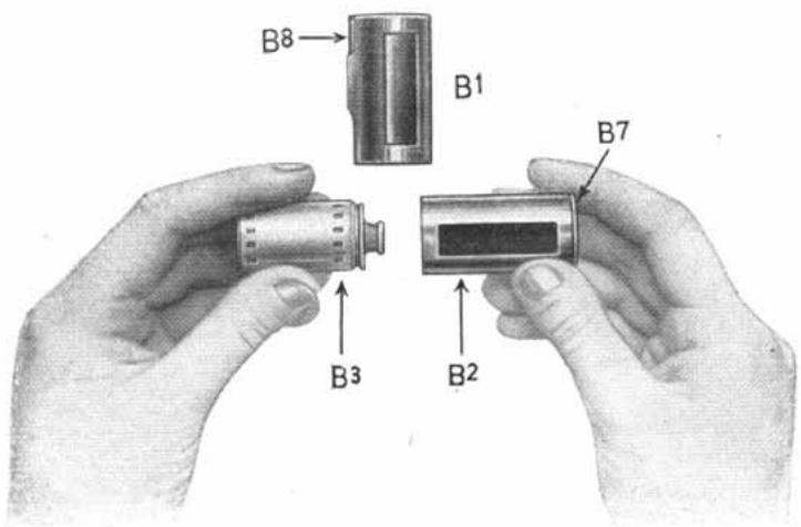
Fig. 14
- Introduce film spool into the inner shell, milled knob first, the beginning of the film lying in the slot.
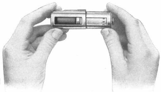
Fig. 15
- Put both together into the outer shell, superimposing the two slots. Pull out the beginning of the film about 2 inches through the open slots.
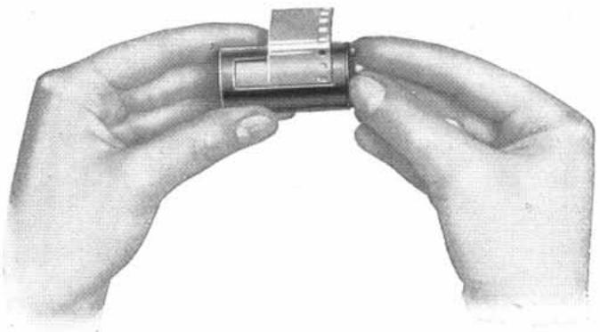
Fig. 16
- Close spool chamber by giving the inner shell half a turn to the left until the safety spring engages at Z.
- Pull out the beginning of the film about 2 to 3 inches from the closed spool chamber, so that it does not slip back.
- If the loaded chamber is not immediately inserted into the camera it should be kept in the aluminium container after the projecting piece has been wound around the chamber.
C. Loading of the Camera in subdued daylight
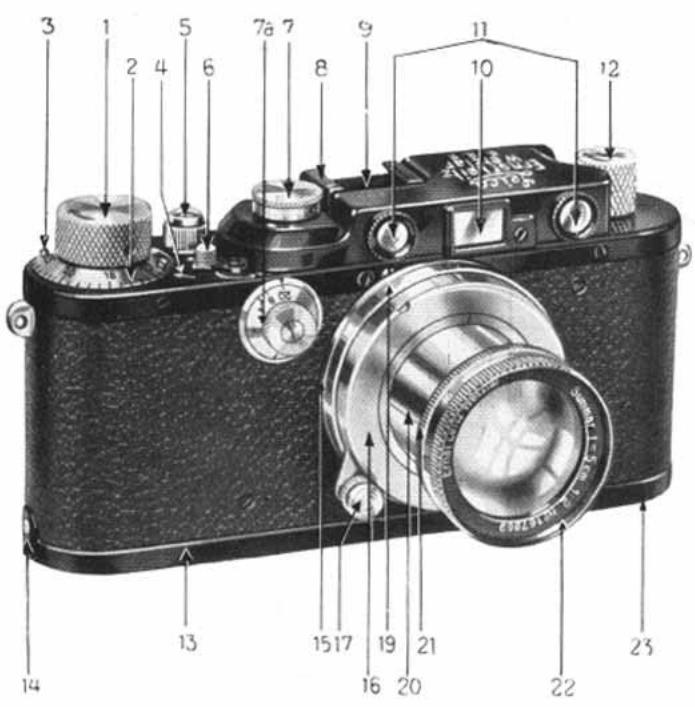
Fig. 17
Note. The loading of the camera should be done in subdued daylight and the slot of the chamber should be covered up as well as possible. The chamber should not be exposed to daylight longer than is absolutely necessary for loading.
- Set the reversing lever 6 from R to A.
- Wind the knob 1 once and release press button 5.
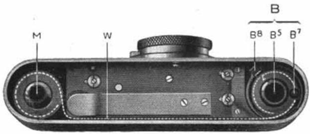
Fig. 18
- The camera having been already opened as per Fig. 2 and the withdrawn spool chamber loaded, now withdraw also the receiving spool M (counter spool).
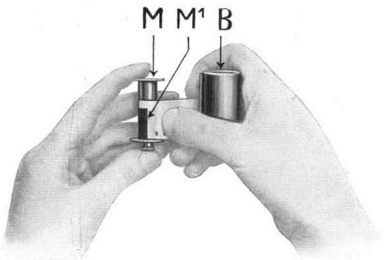
Fig. 19
- Hold receiving spool M with left hand and the loaded chamber B in the right, as shown in Fig.19. Clamp the beginning of the film (emulsion side outwards) under the spring M^1 of the receiving spool. (The perforated edge of the film should lie right against the flange with knob.) Do not, however, wind film on. The tapering of the film should begin close to the slot of the chamber.
Fig. 20
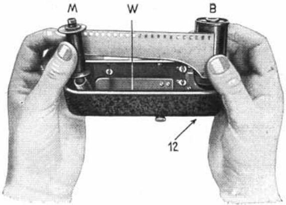
(Pleases also refer to Fig. 18 showing correct position of film by a dotted line)
- Place the opened camera in front of you with the lens away from you. Hold spool chamber in the right hand and the receiving spool in the left hand, and introduce the film into
orad aid
the slit W with the tapered side downwards. (If the spool chamber does not drop right down, give a small turn to backwinding knob 12.) Turn back-winding knob gently in the direction of arrow until the film becomes quite taut.
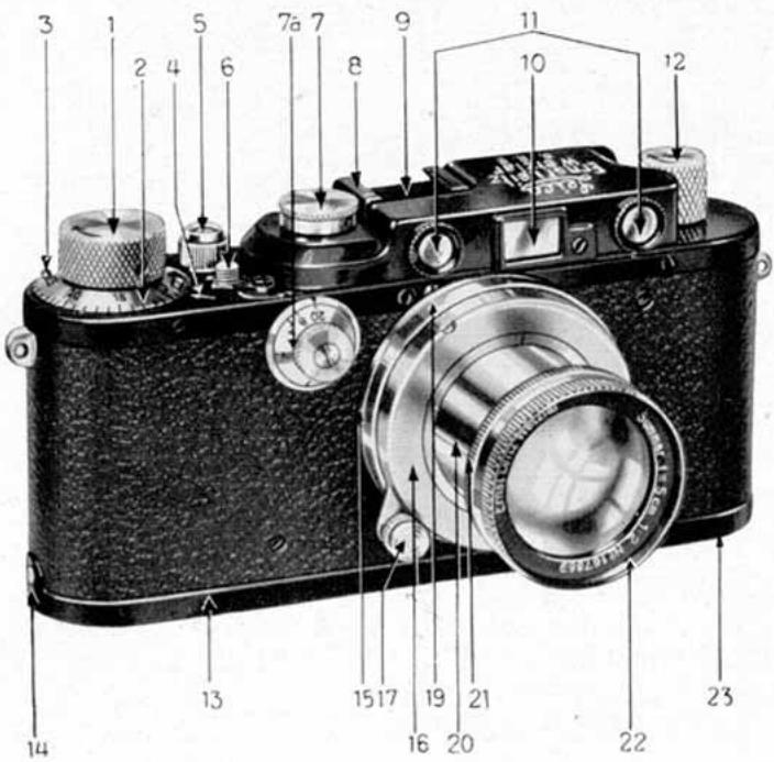
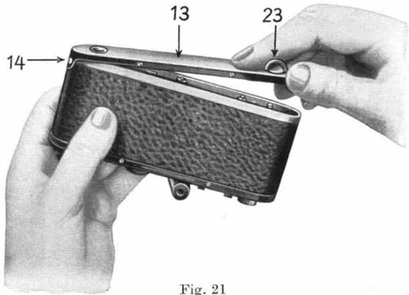
Fig. 22
- Hook camera lid 13 (swivel 23 set to "open") over pin 14. Close lid and
- Turn swivel 23 right over to "closed".
- Wind knob 1 once and release press button. Repeat this once more. (This in order to dispose of the useless tapered beginning of film.)
- Turn counting disc 2 by means of the two lugs 3 towards the left (i.e. against the direction of the arrow of the winding knob 1) to 0 position.
D. Taking the Photograph
-
Pull out lens, and turn it to the right (clockwise) so as to lock it in the bayonet catch.
-
Adjust iris diaphragm by means of lever or ring 21 (Fig. 22).
-
Wind knob 1 in direction of arrow right to stop.
-
See that shutter speed is correct or set it by lifting the speed dial 7, at the same time turning it so that the required figure lies against the index arrow 8. Let go knob which will then settle in position. At Z the shutter remains open as long as the button is pressed down.
4a. See further remarks page 28 re Leica Model III and IIIa.
- Sight the object through range finder 11, turning focusing lever 17 or the lens mount 22 until the two images coincide (fuse into one). Use view-finder 10 to view the whole field and gently (not jerkily) release press button 5. When photographing rapidly moving objects the range finder should be used as view-finder.
E. Unloading of Camera in subdued daylight
-
Release once again press button 5 (whether knob 1 is wound or not).
-
Set reversing lever 6 from A to R.
-
Pull out back-winding knob 12 and turn in direction of arrow until a resistance is felt and wind over this resistance. (This means that the end of the film comes off the spring of the receiving spool.) Give about two more turns (the film is now all wound back into the spool chamber).
-
Turn swivel 23 of camera lid 13 towards the left from "closed" to "open" and remove camera lid.
-
Pull out spool chamber by means of the milled knob and keep in aluminium container for developing.
-
The removing of the film from the spool chamber must only be done in the darkroom, as described under B 4, 1. The inner spool with the film is then removed and the film wound off.
F. The "Standard" Leica Camera
The foregoing instructions for the Leica camera Model IIIa apply to the "Standard" Leica also, except where reference is made to the rangefinder and the adjusting dial for the slow speeds.
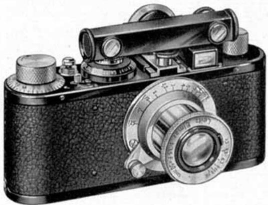
Fig. 23
In the "Standard" Leica, the rangefinder is not coupled with the lens.
In the clamp which will be found near the viewfinder of the "Standard" Leica, a special small holder is inserted, in which the short-base rangefinder is fixed horizontally by means of a pin.
When it is desired to adjust the time of exposure it is only necessary, in order to obtain access to the
speed dial, to push forward the right-hand end of the range finder (see Fig. 24), and after the adjustment has been made to return it to its original position as far as the stop.
Now look through the rangefinder and turn the dial until the two images which are visible therein coincide. Read the
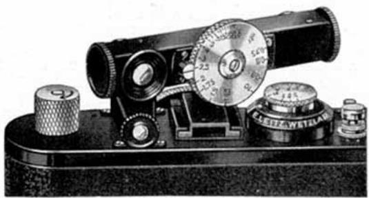
Fig. 24
distance figure, then adjust the index line of the lens focusing mount to this figure, wherupon the exposure may be made.
For shorter distances proceed in the following manner.
Adjust the index of the rangefinder as well as the lens mount right away to the desired distance (for instance, 6 ft.
in the case of portraits). Then approach or retire from the object until the two images which are visible in the finder coincide.
It should be mentioned that the rangefinder may also be used in a vertical position. To do this remove the holder from the clamp and insert in the latter the flange which is on the eyepiece side.
G. Some additional hints on the use of the Leica
Leitz Trimming Template
enables the film to be correctly shaped, and its use also results in the saving of film. It is only required if film is cut from a long length, or when the exposed part of a film has been cut off, and the rest is to be reloaded into the camera.
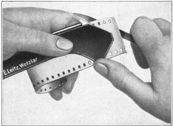
Fig. 25.
Film Trimming Template (Trimming the film for the centre spool)
When using cut lengths of films as supplied by various firms, special trimming is not necessary. On the other hand, when film strips are cut as required from a long length, care must be taken that the two ends of the film are correctly trimmed, as this is absolutely necessary for the satisfactory working of the film winding mechanism in the camera. For this purpose it is advisable to use our new Trimming Template, which also means a saving in film as compared with earlier models.
At the beginning of the roll of film make the wedge-shaped cut for the centre spool and measure off the required length of film. At the end of this make the curved cut for the receiving
spool. When doing this there is made at the same time the correct cut for the receiving spool on the remaining film on the roll. It is therefore not necessary, as was the case with our previous Trimming Templates, to trim the next length of film taken from the roll, so that in this way about 4 ins. of film are saved on every strip.
The manipulation of the Trimming Template is as follows:
To trim the film for the centre spool, unfold the Trimming Template and insert the film, emulsion side underneath, sideways into the narrow slot of the lower plate, so that the end of the film projects slightly beyond the end of the Template. Then close the Template and cut the film along it (see Fig. below).
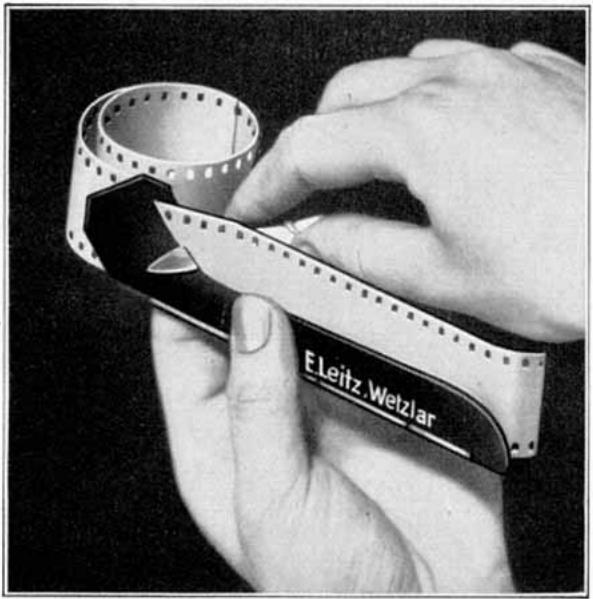
Fig. 26. Trimming Template (Trimming the film for the receiving spool)
Except for the end which lies on the lower plate of the Template, the film remains untouched in the hollow of the hand. The end intended for the receiving spool is placed in the unfolded Template, care being taken to see that the emulsion side of the film is again underneath, and that a small piece projects beyond the end of the Template. The two pins in the Template must engage in two perforations. Then cut along
the curve of the closed Template with a sharp knife (see Fig. 26). When handling the film it must be held only by the edge and any touching of the emulsion must be avoided.
The next piece of film is now ready trimmed for the receiving spool, so that only the cut for the centre spool has to be made at the other end.
Note. Careless trimming of the film leads to trouble in the film winding mechanism, so that the perforations are torn and small pieces of film get into and jam the mechanism. As the film winding mechanism is coupled with the shutter, this is likewise affected. The damage can only be remedied by a careful cleaning of the camera mechanism. This entails expense, which can be avoided if the film is correctly trimmed by means of our Trimming Template.
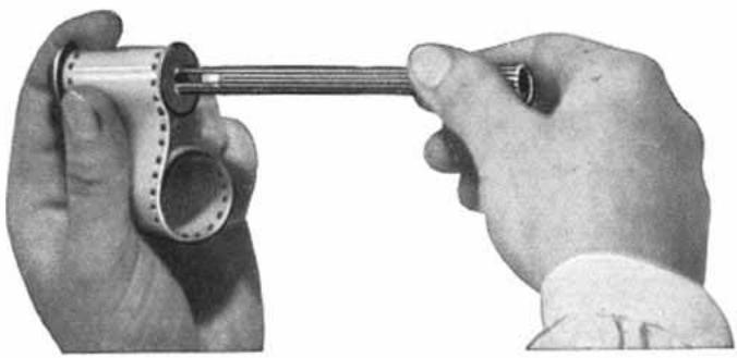
Fig.27.Hand Film Winder
Spooling the film. Winding of the film on to the centre spool is made easier by a special metal Hand Winder. As shown in Fig. 27, the winder is inserted into the spool, on that side which contains the little cross-pin fitting the slit in the Winder.
The Mechanical Winder (Fig. 28) serves the same purpose. This little device is best attached to the edge of a table in the darkroom. To use it, first withdraw the handle of the Winder to its fullest extent, then slip out the spring pressure roll. Now insert the centre spool, with the head of the spool opposite to the handle. When the handle is again inserted as far as possible, it engages in the centre spool, which turns with it. The spring pressure roll is adjustable in the direction of the spool axis, so that it can be slipped into the various spools (the "Standard" Leica, Models II, III and IIIa have the same size of spool, while that of the Leica 250 is different in accordance with its film capacity of 33 ft. As regards the Leica 250, see page 31). The beginning of the film is now
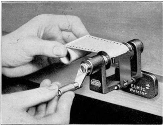
Fig. 28. Mechanical Winder
fixed as instructed in the slit of the centre spool. On turning the handle the film winds itself on to the spool, the spring pressure roll ensuring a uniformly tight winding.
When winding the film on and off care must be taken that no great pressure is put on the film and that the film edges are not squeezed when drawn through the hand. In the former case fogging may easily occur; in the latter so-called "lightenings", i.e. fogging through electric discharges, which extends from the edge of the film into the picture as dark zig-zag lines.
Winding of film in the Leica. The advance of the film from picture to picture is obtained simply by turning the winding knob (Fig. 1, No. 1) right round to the stop, without having to watch a film window as with other roll film cameras.
The evidence that the film is advancing properly is the rotation of the back-winding knob 12 against the direction of the arrow, which must be given particular attention when commencing to photograph. If the back-winding knob, even after several turns of the knob, does not rotate, the reversing lever 6 must be set from A to R, the back-winding knob pulled out (see Fig. 29) and turned in the direction of the arrow, so that the beginning of the film is wound back into the chamber. Then the spool chamber should be taken out and the film inserted again correctly. If these very important points are correctly followed, no difficulties will be experienced.
It will be observed that the release button revolves when the film is being wound back. At the moment when this button ceases to revolve there remains only a small piece of film projecting from the spool chamber. If one continues to wind back, the whole film disappears into the chamber. This will, of course, not be done if the film is to be replaced in the camera, which would not be possible if the beginning of the film did not project from the film chamber.
The setting of the focal plane shutter, which is self-capping, is done by winding the knob 1 (Fig. 1) in the direction of the arrow right up to the stop. The Film is than simultaneously wound on by the correct amount for the next picture.
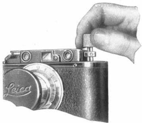
Fig. 29. Extensible back-winding knob
Adjustment of the shutter speeds of the Leica Model II and "Standard" Leica. This is done with the shutter wound. The sutter speed dial 7 (Fig.1) shows the exposure figures, which are fractions of a second (for instance, 20 = 1 / 20 second; Z = Time ). The dial 7 is lifted and turned so that the index arrow 8 points to the required speed, when it is let go. It is advisable to get used to working with the speeds from 1 / 30 to 1 / 60 second and to regulate the intensity by means of the iris diaphragm. The short speeds, i.e. 1 / 200 and 1 / _500 second, are only required for sports scenes in favourable lighting, and then mostly with full open aperture. For time exposures, which of course cannot be made with the camera in the hand, a short wire release is used, which screws on to the press button 5 after the protective ring has been unscrewed. If the focal plane shutter is adjusted to Z, it remains open as long as the button 5 or the wire release is pressed down. The camera is equipped with a normal screw thread for fixing to any tripod.
The shutter speed adjustment of the Leica Model III. Besides the shutter speed dial 7 as on the Leica Model II (see Fig.1), the Model III has a second and small dial 7a on the front of the camera near the lens, which can conveniently be read from above.
If the dial 7a is adjusted to 20(1 / 20) ,the speeds ^1/20 to ^1_/500 on the dial 7 may be adjusted as hitherto, namely: First wind the focal plane shutter by turning the winding knob 1 right round to the stop; lift the dial 7 and turn until the index points to the required speed. The exposure can now be made by pressing the button 5 (or the wire release screwed to it).
If the slow speeds 18, 14, 12 , 1 second are to be used, the speed dial 7 remains set at 20 (engraved "20 - 1"), while the dial 7a is set to the speed required. The exposure is then made in the usual way.
If it is desired to change from a long exposure to a short one, it is only necessary to adjust the dial 7 accordingly, the position of the dial 7a being of no consequence. Only at 1/20 must both knobs be set at 20.
The dial 7a further bears the mark "T". If set to this mark (the dial 7 being set to 1 / _20 ) and the shutter wound, the shutter opens on release and remains open. To close it, do not press the release button again, but merely turn the dial 7a back a little (say to 1 or a little further) when the shutter will close immediately.
If the dial 7 is set to Z and the dial 7a to 1 / _20 , the shutter remains open so long as one presses on the release button.
The dial 7a can be turned either way and is limited by stops. The dial 7a can be set before or after adjusting the speed dial 7.
It should be mentioned that all the intermediate speeds between 1 / 8 , 1 / 4 , 1 / 2 and 1 second can be set these values being proportionate to the placing of the scale (i.e. 3 / 4 sec. being half way between 1 / 2 and 1).
The engraved exposure times, however, may be accurately set by means of notches. With the Leica Model IIIa, the rapid speed dial 7 is scaled up to 1 / _1000 sec. When setting this speed, the dial 7 does not slip in quite so much as with the other speeds.
The release of the press button 5 must be done gently by resting the middle joint of the index finger on the edge of the camera and using the first joint as a lever to press the button. The protective ring facilitates this. Releasing from the back would result in jerking. With slow speeds the risk of jerking can be minimized by placing the thumb under the bottomplate of the camera as a support.
The wire release. For time exposures our screw-on wire release with fixing screw should be used, which may also be used for instantaneous exposures. When unscrewing this release from the press button, it is advisable to hold the speed dial so as to prevent the shutter from being set accidentally. Should this occur, either partly or entirely, it is only necessary to set the shutter fully by turning the winding knob (always right up to the stop).
With the Leica Models II, III and IIIa the rangefinder together with the viewfinder is placed horizontally between the shutter speed dial and the back-winding knob. It is automatically coupled with the helical focusing mount of the lens so that the adjustment of the rangefinder and the focusing of the lens are simultaneous. By this the "ever-readiness" of the Leica has been still further increased.
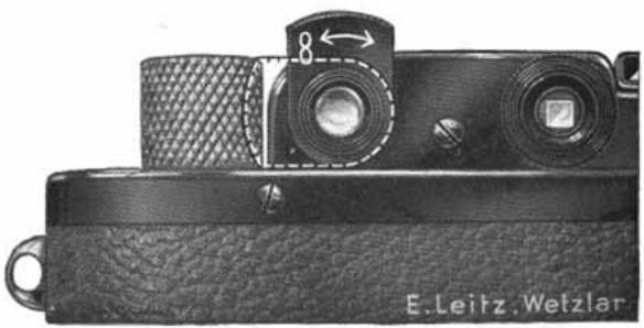
Fig. 30
Correct focus is obtained when the two images appearing in the rangefinder (which never disappear from the field of view, as can happen with a large-base rangefinder) fuse into one (coincidence principle).
In order to increase the ease of measuring still further, the viewing aperture of the rangefinder of the Model III and IIIa Leica is fitted with a magnifying telescope system with a magnification of about 1.5 times. The subjective field of view is therefore increased by about one half, and this considerably facilitates exact and rapid focusing. The eyepiece is adjustable by turning the milled mount, so that everyone can focus near or distant objects to the greatest possible sharpness. Swung up, it is used for distances up to 3^1/4 ft., swung down, for infinity, and set midway, for distances from about 4 ft. to 15 ft.
Steady hold. For slow exposures in the hand it is strongly advised to rest the elbows or at least to lean the body against some support in order to avoid shaking. As the slow speeds are preferably used for near objects, 1/8 and 1/4 sec. will give surprisingly good results with the free hand, also 1/2 sec. with a very steady hand; for 1 sec. however, a support or tripod is necessary.
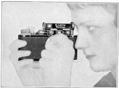
For convenient focusing, the following procedure should be followed:
For horizontal photographs:
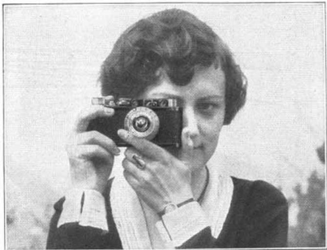
Fig 31
Rest camera against cheek, keeping both elbows close to the body - the right hand clasping the camera - the right index finger ready on press button - the left index finger on the button of the focusing lever - the left thumb supporting the camera on the side.
For upright photographs:
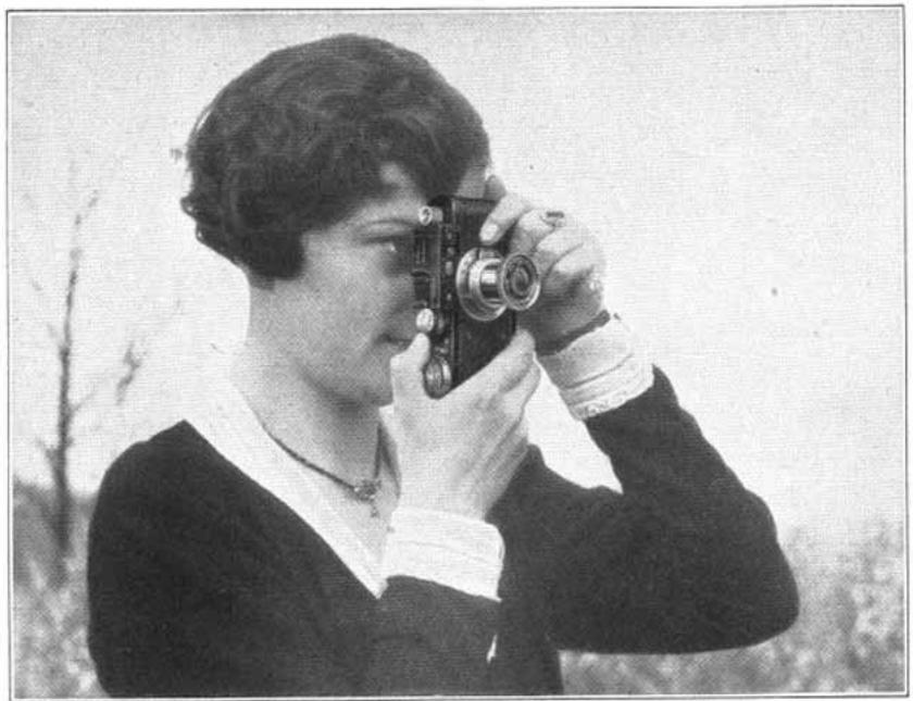
Fig. 32
First Method. Hold camera in right hand from underneath — right thumb stretched over winding knob and resting on press button, thumb must not touch speed dial — right elbow against body — operate focusing lever with index or middle finger of left hand whilst left thumb steadies camera against forehead.
The method as set out above obviates shaking with utmost certainty. Obviously, the thumb must release the press button gently. To hold the camera in this way is particularly convenient when wearing a hat with a broad brim.
Second Method. This method is also greatly favoured by many.
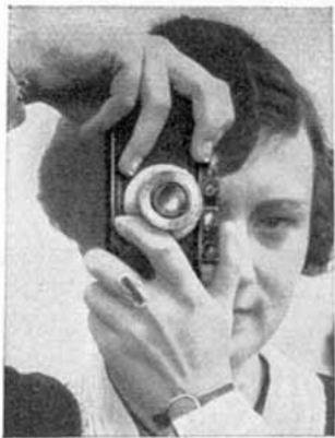
Fig. 32a
Right hand on top - right index finger on press button left index finger actuating focusing lever - left thumb supporting camera.
The viewfinder is fitted in the middle of the rangefinder housing. It is a direct-vision finder, and is to be held close to the eye. The field of view gives the exact size of the photographic image at 9-12 ft.; at infinity rather more is on the negative, and at 3-6 ft. rather less. This normal viewfinder is intended for use with the standard lens "Elmar" F/3.5, 5 cm. also the "Hektor" F/2.5, 5 cm and the "Summar" F/2, 5 cm. Lenses of other focal length require the use of our Universal Viewfinder, which is slipped into the clip on top of the camera. For particulars of Universal Viewfinders see page 45.
H. Leica 250
As shown in the illustration, this model differs in form from the Model IIIa only by reason of the larger film chambers.
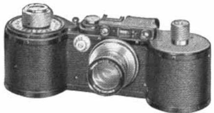
Fig. 33
Each chamber holds a piece of film of 33 ft. length, which is sufficient for rather more than 250 pictures.
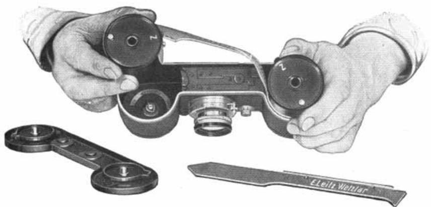
Fig. 34
The manipulation differs from that of the Model IIIa only in the following points:
Loading the film chambers: As the Leica 250 has a film chamber at both ends, two knobs are provided for locking the base cover plate, which must first of all be opened.
One of the chambers is loaded with film in the darkroom in the usual way, and the projecting piece of film is trimmed with a special template, which conforms with the length of the film track in the camera. The beginning of the film is now fastened under the spring of the second spool chamber, the long uncut edge of the film against the spool disc with knob. This chamber also is then closed in the usual way. The two closed chambers are now placed in the camera, so that the film slips in the narrow guide slots (see Fig. 34). Care must be taken that the knob on the underside of each film chamber snaps into position, by gently turning the chamber. This is easily effected, because the screws which hold the spring closing the chamber have specially high heads, which compel one to insert the chambers in approximately the right position. The base cover plate can only be closed if the two film chambers are correctly placed. When the two locks are closed, the two chambers open together. Finally, the film is tightened by gently turning the back winding knob as well as the milled disc on top of the winding knob in the direction of the arrow.
The film is not wound back after exposure, as this would be too inconvenient on account of the length of the film.
The spool chambers may be changed in a dull light.
If it is desired to take out a piece of film which is not entirely exposed, before opening the base cover plate the film must be slackened a little by turning the above mentioned milled disc in the opposite direction to the arrow. After removing the cover, both chambers may then be taken out or the film may be cut with the cutting knife supplied and the winding-on spool only, which contains the exposed piece of film, taken out.
It should be observed that when fastening the film in the chamber, the end should not be doubled over, as otherwise the film cannot come out of the chamber after exposure. Has this been done accidentally, before opening the camera the film must be loosened in the manner described above and both chambers are than removed and the fastened end of the film released.
I. Accessories for single exposures
1. A special accessory for single exposures
with dark slide and focusing screen
The device consists of a black lacquered light metal body, in the back of which is the focusing screen or darkslide, the Leica lens being screwed in in front. One of the well known
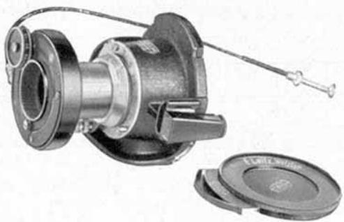
Fig. 35a
Leica viewfinders can be fitted on top; on the side and underneath the housing bushes are provided for upright or horizontal pictures on a tripod.
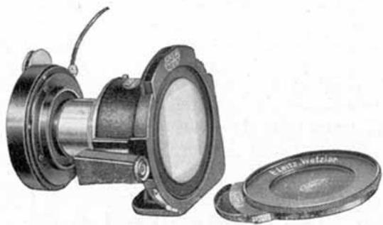
Fig. 35b
The body of the device does not contain a shutter. An Ibsor shutter is provided which is fitted on to the lens and which allows of instantaneous exposures from 1 - 1 / _125 sec. and time exposures.
This shutter can be supplied in two sizes. The smaller one fits the lenses "Leitz-Elmar" F/3.5, 3.5 cm. (wide angle),
"Leitz-Elmar" F/3.5, 5 cm. (standard) and "Leitz-Elmar" F/6.3, 10.5 cm. The larger one fits all lenses except the "Leitz-Elmar" 13.5 cm., "Leitz-Hektor" 7.3 cm. and 13.5 cm. "Leitz-Thambar" 9 cm. and "Leitz-Telyt" 20 cm. For photomicrographs in conjunction with our Micro Attachment, the shutter is not used, as this attachment contains a shutter. The codeword for the device with the small Ibsor shutter is "Oleyo", that for the device with the large shutter "Oligo".
Only screw-in filters can be used with this device.
The manipulation of the device is simple in the extreme. After removing the cover plate of the darkslide in the darkroom, it is loaded with a piece of film of standard width and about 40mm long, cut from a roll of standard cinematograph film (or from a film in a Leica film chamber). The width of the slide is exactly 40mm , and can therefore be used as a guide for the length of the piece of film to be cut. The cover plate is then pressed back into position, care being taken to see that the film in the slide is not pinched. The slide is then ready for use.
Before making the exposure, the focusing screen is placed in the groove in the slide, where it is held by a spring, and the lens is screwed in in front. The subject is posed and focused on the ground glass. The diaphragm is then set to the desired aperture and the shutter slipped on.
To make the exposure, the darkslide is inserted in place of the focusing screen. By simultaneously pressing gently on the catch, both parts can be inserted or removed conveniently and without shaking. If the placing of the object has been disturbed through incorrect manipulation, a glance through the finder is sufficient to put this right. The sheath of the slide must of course be drawn before the exposure.
2. The single film holder
Even simpler and cheaper, though less universal in use, than the special device described above is the Single Film Holder "Fhkoo" for the Leica. This comprises a simple metal frame with two slots, by means of which a piece of film 8cm long is held. This piece of film can only be inserted in the holder in the darkroom and the placing of the holder in the Leica must likewise be done there.
When inserting the holder a certain amount of care must be exercised to prevent the film from getting scratched. In the first place, only films with an emulsion protecting surface may be used, i.e. films which have a special protective layer over the emulsion. This is the case with most films on the
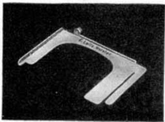
Fig. 36
market, but not, for instance, with diapositive film and infrared film. The emulsion should further be protected by inserting a piece of blank film together with the holder, holding it before the emulsion. When the holder is firmly inserted, the piece of blank film is slowly withdrawn.
The holder may only be removed from the Leica in the darkroom. First raise the holder a little by means of its small knob, insert a piece of blank film in front of the emulsion and then withdraw the holder.
To hold firmly the pieces of film which are used in this device, our film holder "Fialt" may be used with advantage.
K. The Interchangeable Leica Lenses
Every Leica camera is now fitted with a lens-changing flange which makes it possible to interchange lenses of various focal lengths without any difficulty, as the camera as well as the lenses are all standardised. The lenses are simply screwed moderately tight into the changing-flange. In order to ensure accuracy for all time we employ a changing screw flange and not a rapid or bayonet thread. When changing lenses the open camera should not be exposed to bright light but held with the aperture towards the body until the lens is screwed in.
All Leica lenses are high class Leitz anastigmats and their optical data are chosen so as to suit various purposes. There is therefore hardly a branch of photography to which the Leica camera cannot be applied with success.
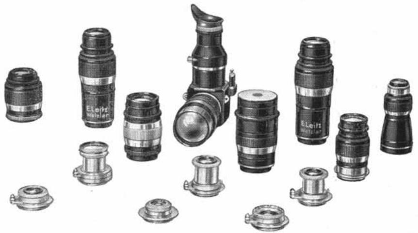
Fig. 37
The following Leica lenses are supplied:
"Leitz-Elmar" F/3.5, 5 cm. focus (standard lens),
"Leitz-Elmar" F/3.5, 3.5 cm. focus (wide-angle lens),
"Leitz-Elmar F/4.5, 3.5 cm. focus (snapshot lens, without coupling),
"Leitz-Elmar F/4, 9 cm. focus (portrait and distance lens),
"Leitz-Elmar" F/6.3, 10.5 cm. focus (light distance lens),
"Leitz-Elmar F/4.5, 13.5 cm. focus (distance lens),
"Leitz-Hektor" F/2.5, 5 cm. focus (rapid universal lens),
"Leitz-Hektor" F/1.9, 7.3 cm. focus (ultra-rapid lens of long focal length),
"Leitz-Hektor F/4.5, 13.5 cm. focus (distance lens having great resolving power),
"Leitz-Hektor" F/6.3, 2.8 cm. focus (extra wide-angle lens),
"Leitz-Summar F/2, 5 cm. focus (ultra-rapid universal lens),
"Leitz-Telyt F/4.5, 20 cm. focus (tele lens with reflex focusing),
"Leitz-Thambar"F/2.2, 9 cm. focus (soft focus portrait lens of great rapidity).
The Standard Lens "Leitz-Elmar" F/3.5, 5 cm. focus. Owing to the favourable choice of focal length and relative aperture, this lens is the most suitable universal lens for small size negative photography, and cannot be displaced by any of the following special lenses, for it has a particularly well graded depth of focus, resulting in a remarkably realistic effect in respect of space. It will therefore always remain the most ideal lens for the majority of amateur photographers.
The tubular socket of the "Leitz-Elmar" 5cm lens is pulled out for photographing and locked in a bayonet catch by turning it to the right (clockwise). When the camera is not in use the lens socket is turned to the left and pushed into the camera body.
The "Leitz-Elmar" lens F/3.5, 3.5 cm. focus is intended primarily for architectural photographs. With these it often happens that the practicable distance between the camera and the building is not sufficient to show the latter in its entirety upon the negative. Since the 3.5 cm. lens embraces an angle of nearly 65^ , and the 5 cm. lens only an angle of 48^ , the former has an undoubted advantage over the latter when architectural subjects are to be photographed. The smaller lens is also very useful for interiors. This lens, it should be noted, is mounted in an inextensible tube. We should like to mention that photographs of interiors are possible with long exposures even without a tripod, by holding the camera with its back against a wall. For the 3.5 cm. lens the universal view-finder is used. (Particulars on view-finders will be found on page 45.)
This lens may also be used for photographing general subjects, especially when taking photographs of objects at rapidly changing distances. By this means, one can avoid constantly altering the focus, as the great depth of field resulting from the short focus makes it possible to keep a large depth of field in sharp focus at a constant focal adjustment. For instance, at an aperture F / 4.5 and the focus set to 21 ft., the field extends from 9^1 / _2 ft. to infinity. Further data may be obtained from our depth of focus tables.
The "Leitz-Elmar" lens 3.5cm focus also has a working aperture of F/3.5, although a slight vignetting effect due to the large aperture and wide angle is removed only by stopping down to 4.5 or 6.3.
The "Leitz-Elmar" F/4.5, 3.5 cm. focus is specially designed as a snapshot lens, as on account of its short focal length and reduced aperture it gives a great depth of focus. The lens is not coupled with the rangefinder and is primarily intended for use with the "Standard" Leica. It can be set to only four fixed distances, 6 ft., 9 ft., 30 ft. and infinity.
The "Leitz-Elmar" Lens F/6.3, 10.5cm focus is a relatively small and light distance lens, weighing about 7 ozs., and is particularly favoured by mountaineers. Its lesser aperture is in most cases perfectly sufficient, as when photographing distant views one mostly has to stop down to 6.3 in any case, in order to overcome unsharpness which may arise due to distant haze. Those who demand a greater aperture (implying increased weight and volume) will choose one of the following distance lenses.
The "Leitz-Elmar" Lenses F/4, 9 cm. focus and F/4.5, 13.5 cm. focus are mainly used for photographing distant views, but they are also very suitable for portraits when it is desired to fill the whole negative with head or head and shoulders without the necessity of getting too close to the subject. Owing to the increased working distance they are frequently used to avoid distortion of proportion. These lenses are used with our universal view-finders (see page 45). The image angle for Leica negatives of the "Leitz-Elmar" 9 cm. lens is 27^ and of the "Leitz-Elmar" lens 13.5 cm. 19^ .
The "Leitz Elmar" lens 13.5cm is approximately 5^ long and weighs 14^3 / 4 ozs., whilst the "Leitz Elmar" lens 9cm measures only 3^ and weighs 10 ozs. Where it is required, therefore, to have a distance lens of fairly wide aperture but small size and weight, the latter lens will be preferred.
The "Leitz-Hektor" F/4.5, 13.5 cm covers the same range of application as the "Leitz Elmar" 13.5 cm., but surpasses the latter in that it has a higher resolving power.
When working with these long focal length lenses it is particularly important to keep the camera steady. When using the 13.5cm lens the left hand should hold the lens mount from below, in rifle fashion, whilst the right hand should control the release. This should not be done in jerks but by gradually applying pressure as when working the trigger of a rifle. Preferably a tripod stand should be used with this lens, in order to avoid blurred pictures.
The "Leitz-Hektor" lens F/2.5, 5 cm. focus meets the wishes of those Leica photographers who desire to obtain snapshots under unfavourable lighting conditions both out of doors and indoors. The "Leitz-Hektor" lens is not a soft picture producer like many other lenses of this aperture, although it naturally does not quite attain the same crisp definition as the "Leitz-Elmar" lens.
The tubular socket of the "Leitz-Hektor" 5cm lens is pulled out for photographing in the same way as the standard lens and locked in a bayonet catch by turning it to the right (clockwise). When the camera is not in use the lens socket is turned to the left and pushed into the camera body.
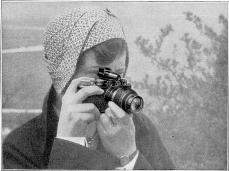
Fig. 38
The "Leitz-Hektor" F/6.3, 2.8 cm. focus, is purely a wide-angle lens with an angle of image of 76^ . Even at the remarkably large aperture for this angle of F/6.3 it gives absolutely sharp negatives entirely free from distortion. We wish to mention particularly that this lens also is coupled with the rangefinder, which has not been done before with lenses of this focal length. The relatively great light transmitting capacity of the lens permits of making short instantaneous exposures even under unfavourable lighting conditions.
The "Leitz-Summar" F / 2,5cm is a first-class universal lens. Even at full aperture, this lens gives critical definition right to the very corners. The particularly good chromatic correction is especially important in conjunction with the use of modern panchromatic films. The construction of this lens is such that pictures taken with it have a definite plastic effect. The lens is therefore equally suitable for all kinds of artificial light and Press photography as for general amateur photography.
The "Leitz-Summar" is obtainable in collapsible or non-collapsible mount.
The "collapsible Leitz-Summar" has arrows at right angles to each other on the lens socket-tube, for use when pulling out
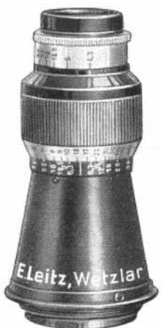
Fig. 39a. "Leitz-Elmar" lens F/6.3, 10.5 cm. focus
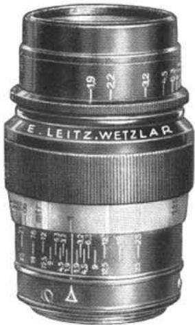
Fig. 39b. "Leitz-Hektor" lens F/1.9, 7.3 cm. focus
and locking the lens. On the ring which encircles the lens socket-tube, there is a short line. This line must be flush
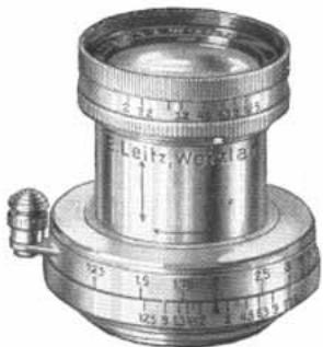
Fig.39c. "Summar"F/2, 5cm., collapsible mount
with the arrow in the longitudinal direction of the socket-tube. The lens can then be drawn out completely, and the second arrow then appears horizontally on the socket-tube (see Fig. 39c), indicating the direction in which to lock the lens. The lens is simply turned right round to the stop and is then securely locked. The aperture figures can be conveniently read from above. When locking the lens, hold only the first milled ring, without touching the milled ring behind, which serves for adjusting the aperture.
The aperture should be set only after the lens has been locked.
Owing to its great light transmitting capacity, the "Leitz-Hektor" lens F/1.9, 7.3 cm. is of particular importance for the Press photographer and where a longer focus for greater distances is desirable. At full aperture attention must be paid
to correct setting, in order to remain within the depth of field. As the lens is stopped down, the image gains rapidly in sharpness, so that it is also suitable for landscape photography.
At full aperture it is an ideal lens for portraits, as the long focal length and large aperture result in a neutral background, an effect which is often desirable in portraiture.
The "Leitz-Telyt" F/4.5, 20 cm. focus is, like the long distance lenses of 13.5cm focus, mainly for distance photographs, but it may also be employed successfully for portraits (large heads, etc.), sport and Press photography at great distances, photographs of animals in zoological gardens and in their natural surroundings. With the "Leitz-Telyt" the image ratio is rather more than one half larger than with the lenses of 13.5cm . focus; accordingly the angle of image of the "Leitz-Telyt" is only 12^ . With this small angle an exact determination of the field as well as exact compensation for parallax with one of the ordinary view-finders is difficult. The lens is therefore equipped with a reflex arrangement in which parallax is eliminated as a matter of course and the field of view can be observed on the ground glass screen. The focus is also adjusted with this reflex arrangement, thus eliminating the coupling with the rangefinder. The viewing of the image on the ground glass screen and the focusing are simplified by a X 5 and a X 30 magnifier.
It is advisable always to use the lens on a tripod, to avoid shaking. The exposure is made by means of a double release, which in rapid succession removes the mirror out of the path of the rays and then operates the shutter. A detailed description and instructions for the use of this lens are contained in the special leaflet "Leitz-Telyt" F/4.5, 20 cm.
The "Leitz-Hektor" F/4.5, 13.5 cm. can also, in a shorter mount without coupling, be used interchangeably with the "Leitz-Telyt" in conjunction with the reflex arrangement.
The Leitz-Thambar F/2.2, 9 cm. focus gives at full aperture and moderately stopped down, soft definition and is therefore chiefly suitable for portraits and for certain landscape photographs; when stopped down further the definition becomes sharp, so that it may also be used for sharp landscape and distance photographs.
The degree of the soft effect obtained is controllable within wide limits by the use of the normal iris diaphragm and an addition screw-in central diaphragm. It is greatest with the iris diaphragm at full aperture and with the central diaphragm screwed in, and somewhat less when working with the iris diaphragm at full aperture and without the addition screw-in diaphragm. Stopping down the iris diaphragm lessens the softness, but only then uniformly over the whole field when the central diaphragm is screwed in.
The white aperture scale on the "Leitz-Thambar" applies when working without the central diaphragm, the red one when the central diaphragm is screwed in.
The image ratio of the various lenses is preportionate to their focal length, i.e. 28:35:50 ; 73:90 ; 105:135:200 .
The helical mount. Every lens possesses its own helical mount for focusing. That of the "Leitz-Elmar" lenses 3.5 and 5cm also that of the Leitz-Hektor lens 5cm is actuated by the focusing lever 17 (Fig.1); that of all other lenses, however, by means of the large milled ring (see Fig. 38 and 39b). An index line indicates the distance.
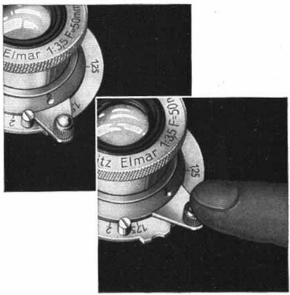
Fig. 40. The infinity catch
In addition to the main index line, all Leica lenses except the "Leitz-Elmar" 3.5cm now have a second index denoted by R, which serves for focusing when taking infra-red photographs. The object is focused differently according to whether the lens is coupled with the rangefinder (Leicas II and III, Leica 250) or not (Leica I and "Standard"). When the lens is not coupled with the rangefinder, the distance is read off on the rangefinder scale and the lens set to that distance by means of the index R. When the lens is coupled and in the case of the accessory for single exposures ("Oleyo", "Oligo"), the lens is first focused in the usual manner, then the helical mount displaced until the index R points to that position on the scale which was first indicated by the main index.
The infinity catch. If the helical mount has reached the infinity position () , it is automatically engaged and locked. By pressure on the button of the focusing lever it may be released. This device (see Fig. 40) is fitted to the lenses "Leitz-Elmar" 3.5 and 5cm , also the "Leitz-Hektor" and "Leitz-Summar" 5cm lenses.
Coupling. The mechanism of the built-in rangefinder is interconnected with the helical focusing mount of the lens by means of special devices. By screwing the lens into the camera, the connection is automatically ensured. The automatic coupling represents fine motion mechanism of highest precision and guarantees utmost convenience and greatest rapidity in photographing with the Leica.
The diaphragm of the "Leitz-Elmar" 3.5 and 5cm and "Leitz-Hektor" 5cm . lenses is adjusted by means of a small lever with index line. The other lenses have a thin milled ring for adjusting the diaphragm. The figures read off are the relative apertures of the lenses. The ratio of time of exposure compared with the full open aperture is as follows:
Relative aperture 1.9 2.0 2.6 3.2 3.5 4.5 6.3 9 12.5 18
Ratio of exposure 0.36 0.4 0.6 1 1.2 2 4 8 16 32
The excellent quality of our photographic lenses is due not only to progress in the art of computation and more exact methods of production, but also to the use of special kinds of glass. Maintaining the high reputation of our Works, it goes without saying that we use optical glass of the very best quality only; in spite of all technical advancement, however, it has not yet been practicable to produce glass having certain novel optical properties so as to leave it entirely free from small air bubbles. Hence, complaints as to these are not justified, since their presence in our special lenses merely indicates the use of glass with valuable physical properties. Isolated bubbles, such as are allowed to pass through our controls, have no influence whatever on the quality of the image, and the loss in light intensity is absolutely negligible.
The Depth of Focus Scale
To enable one to read off figures for the depth of focus for the different lens apertures directly from the Leica camera, a special scale has been provided on the lens mount bearing the aperture figures from 1.9, 2, 2.5 or 3.5 respectively to 18, diverging from either side of the central index mark. (See Figs. 39 and 41.)
The following is the method of ascertaining the depth of focus.
First, set the main index to the appropriate distance figure obtained by measuring or guessing of the distance to the object, say 12 feet. With aperture 6.3 the two index lines marked 6.3 on the depth of focus scale indicate a range of depth of focus from 9 to 18 feet; with aperture 4.5 a range from 10 to 15 feet; and with aperture 18.0 a range from 6 feet to "infinity".
If it is desired to obtain the utmost depth of focus for a distant view with foreground, not the main index is set to infinity but that index line of the depth of focus scale which corresponds to the aperture used. With aperture 18.0 the depth of focus then covers a range from 6^1 / 2 feet to "infinity", and with aperture 6.3 a range from 18 feet to "infinity".
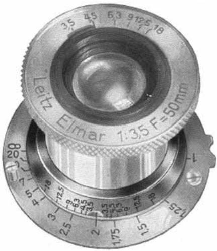
Fig.41. The depth of focus scale
It is understood that the reading of the depth of focal range is limited by the two ends of the distance scale, namely, 3.5 feet and "infinity". All figures on the depth of focus scale appearing beyond these limits have no significance on the reading. In other words, when setting the main index to 3.5 feet the near point of the depth of focus range cannot be read off. When set to 100 feet the far point of the depth of focus range for aperture 3.5 lies at infinity, and similarly for all smaller apertures, although the far index of these small apertures extends beyond infinity.
The reading of the depth of focus at the depth-of-focus scale is sufficiently accurate for all practical purposes. A specially computed table issued by us contains more accurate figures, the calculation of which is based on a circle of confusion of 130 th mm.
The beginner will find it advisable not to worry about the depth of focus scale, and especially not about the tables. His first aim will be to obtain his results with two settings of the focusing scale: for distant views, stop at 6.3 and setting on infinity, for portraits, full lens aperture and exact focusing on his subject. Only when he approaches more difficult subjects will he learn to avail himself of the depth of focus scale and later on of the tables, should he have to work very exactly.
L. Accessories to the Leica
Leitz Angular View-Finder
for the Leica Camera with 5cm lens.
The Leitz Angular View-Finder ("Wintu") enables one to make exposures without attracting attention as the sighting during sunlight.
device lies at right angles to the object to be photographed: that is, the photograph is taken as it were "round the corner". The forked bracket of the angularviewfinder is slipped into the clip on top of the camera and the small prism attached to the finder is switched in front of the eyepiece of
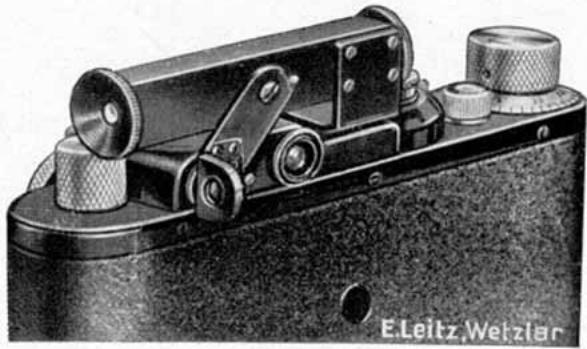
Fig.42. The Angular View-Finder
the range finder (see Fig. 42). The camera is held during the exposure as illustrated in Fig. 43. Focusing by means of the
reflecting prism of the angular view-finder is simplified if the object is first sighted in the eyepiece of the finder.
The angular view finder can only be used with the Leica camera and Leica lenses of 5cm focal length. The image appears right and left reversed.
Fig.43.How to use the Angular View-Finder
Leitz Universal View-Finders
for the Leica camera with interchangeable lenses
When using the Leica camera with interchangeable lenses, the various fields covered by the different lenses are determined with the aid of special optical viewfinders which slip in the clip on top of the camera body.
The Large Universal Finder "Vidom"
for all Leica lenses
This finder contains an oblong diaphragm which is adjustable in size. By means of a milled ring the field of view is reduced or increased. The proportion of the sides remains
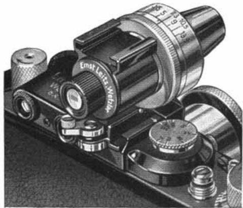
Fig. 44
The Large Universal View-Finder
always 2:3. The milled ring is engraved with the various focal lengths of the Leica lenses. The diaphragm shows, therefore, only the field of that lens for the focal length of which the index line has been set, and this for distances from 30 feet to infinity () . A second shorter index line close to the other is referred to when taking close-ups, i.e. for distances from 3.5 to 6 feet. It gives the reduced field obtained at these short ranges with all Leica lenses, with the
exception of the wide-angle lens. For distances between 9 and 30 feet the milled ring is best set between the two index lines.
For compensation of the parallax between finder and lens (displacement of both optical axes) this view-finder is fitted with a cam and lever motion for tilting the finder. By this arrangement it is ensured that an object sighted through the centre of the finder appears really in the centre of the photograph. The parallactic effect is not noticeable at distances over 12 feet. For shorter distances, however, it has to be compensated for by tilting the finder. This is done with the small lever underneath the eyepiece which is marked with figures for the respective short distances and for infinity () .
When taking a portrait, for instance, after having focused the camera, the distance is read off at the focusing scale of the lens, and the parallax lever set accordingly.
When taking a portrait, for instance, after having focused the camera, the distance is read off at the focusing scale of the lens and the small index line of the milled ring set to the focal length of the lens used; lastly the parallax lever is set according to the distance read off.
For changing over from horizontal to upright pictures and vice versa, see page 48.
The small Universal Finder
for specific lens combinations
Unlike the large Universal Finder "Vidom", the second model is only designed for certain specific combinations of lenses, as follows:
Model I "Viuna" for 3.5-5-7.3 cm. lenses,
II "Vizwo" 3.5-5-9 cm.lenses,
III "Vitre" 3.5-5-10.5 cm. lenses.
IV "Vifur" 3.5-5-13.5 cm. lenses.
The various fields are shown on a line drawn plate. Fig. 45a shows one of these line drawn plates as it appears when seen through the finder.
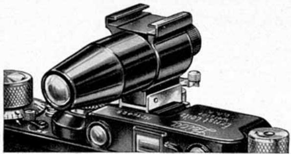
Fig. 45. The Small Universal View-Finder on the Leica
The broad outer border indicates the field covered by the wide-angle "Leitz-Elmar" lens of 3.5cm focus; the second broad line is for the standard lens 5cm , the third for the long-focus distance lens "Leitz-Elmar" 13.5cm . These fields are all correct for distances over 30 ft. The thin lines within the various fields, however, are correct for close-ups (at about 6 ft.) and show the reduced field obtained at these short ranges. A small cross in the centre simplifies central sighting.
The parallax between finder and lens is compensated for by tilting the finder. This is done as described above by means of a small lever fitted underneath the eyepiece.
Both models are built after the principle of a small astronomical telescope in combination with an image-erecting prism. The image, however, appears right and left reversed. The unique arrangement of these finders has the special and important advantage that any slight tilt of the camera will cause the image seen through the finder to assume a pronouncedly oblique position. The tilt of the image in the finder, due to the prism arrangement, is twice as great as that of the camera
body itself, thus providing an excellent means of setting the camera accurately horizontal or vertical, as the case may be.
When the camera is turned for taking upright pictures, the image in both finders appears upside down. In order to be able to see the view in its natural position, the prism in
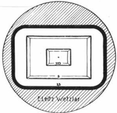
Fig. 45a. The field of view in the small Universal Finder "Vifur" (Model IV)
the eyepiece is made to turn through 90^ . The limits of the movement are felt by definite stops. It should be noted that with the finder in working position, the oblong diaphragm in the eyepiece should always be set horizontally.
When following rapidly moving objects, owing to the left and right mirror reversal of the image in the finder, it is advisable to keep both eyes open so as to retain the object more easily in the centre.
For finding the proper pictorial composition the universal finder is used without camera. Sighting through the
finder shows immediately whether the desired effect can be obtained with any particular lens. This is a great convenience, especially when working with long focal length lenses, as one need not take the camera and lenses from the case until the best position has been found.
Fitting the Universal Finders. The universal finders slip into the clip provided on top of the Leica body. A similar clip is fitted to the top of the universal finders to enable one to attach a separate range finder. Care must be taken to ensure that the universal finder is always pushed into the clip as far as it will go.
Subsequent Fitting of a Universal Finder. The universal finders will, without special adaptation, fit all Leica cameras, and an adjustment of the clip on previously supplied cameras is not as a rule necessary. If in particular cases the image of the finder does not exactly agree with the image obtained on the film, it is advisable to send both finder and camera to us for adjustment.
The Sports Finder
For the lenses of 7.3 to 13.5cm focal length, a Sports Finder is supplied through which a rapidly moving object can
be observed before it actually enters the field of view of the Leica. The field of the Leica is defined by a plainly visible light rectangle.
Leitz Frame Finder
for the Leica camera
This finder can be highly recommended, especially for sports photography and for exposures from aeroplanes.
Its most noteworthy feature is that it covers all possibilities of use, because it is not only of service for the standard lens of 5cm focus, but also shows the angle of field for the 3.5cm
and 9 cm. "Leitz-Elmar" lenses, as well as the 7.3 cm. "Leitz-Hektor" lens.
For this purpose the image frame can be rotated through 180^ against two stops. The normal position as shown in the illustration indicates the fields of the 5cm and 9cm lenses, while the field of the 3.5 and 7.3cm lenses is shown when the frame is swung round, owing to its eccentric motion. By fixing a special mask on the front side, it also serves in its normal position to give the field of the 13.5cm lenses and in the opposite
position, that of the 10.5cm lenses. So as to facilitate the exact alignment of the narrow angle of view when the long focus lenses of 10.5cm and 13.5cm focus are used, a pin-hole can be clipped in position in front of the rear sighting aperture. This pin-hole can, however, not be used with the other lenses, as it would cause the field of view to appear too much enlarged.
Parallax in the case of close-ups can be compensated for by vertical displacement of the back sight of the finder. To this purpose it is engraved with notations , 6 ft. and 3.5 ft.
When using the lenses of 3.5 to 9cm focus care should be taken to look straight through the frame of the finder; this ensures the exact coincidence of the centre of the field and its boundaries with those of the negative on the film. The sighting frame is always held close to the eye. The Frame Finder can be collapsed when not in use.
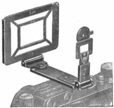
Fig. 46
Leitz Reflecting Finder
for the Leica camera
Contrary to the principle of direct vision at eye-level embodied in all other Leica viewfinders (normal, Universal and Angular Finders), the Reflecting Finder is constructed on the principle of the well-known reflecting finders. The image is consequently not viewed at eye-level but from a position
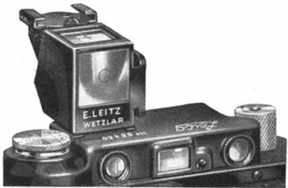
Fig. 47
The Reflecting View-Finder on the Leica
about 8 inches above the finder. This finder is found convenient mainly where it is required to photograph from a lower position, as, for instance, when photographing children, small animals etc.
The finder consists of a housing containing a so-called "penta" prism in conjunction with a negative lens (Newton
finder). This novel combination results in a very clear, bright and sharply-defined image.
To indicate the size of field for horizontal or vertical photographs the four corners are blocked out in the usual way. The image is upright and correct as to right and left. The field of view corresponds to that of the Leica lenses of 5cm . focal length and Leica negative size 24× 36mm
On special request this finder can also be supplied equipped with a negative front lens, enabling it to be used with the "Leitz-Elmar" 3.5cm wide angle lens.
The finder has engraved on top small cross-lines and in front a small circle. Sighting should be done with one eye only, and the cross-lines should appear in the centre of the circle so as to ensure that the camera is not slanting.
A special clip fitted to the side of the finder may accommodate a case level. The Reflecting Finder has two fixing flanges for horizontal and vertical pictures and is slipped into the clip on top of the camera body.
Leitz Slow-Speed Attachment
for the Leica Camera
The Slow-Speed Attachment screws on the release button of the Leica camera Model I, "Standard" and Model II and allows of obtaining with these models also the same slow speeds of 1, 1/2, 1/4 and 1/8 second as with the Model III, without any conversion being necessary.
The application is as follows: Wind the shutter of the camera
and adjust the shutter speed dial to Z (time). Then wind the Slow-speed Attachment by gripping with thumb and forefinger the two studs of the winder, and turn clockwise right to the stop. Only after winding can the desired speed be set by lifting the longer part of the winder from underneath and then turning it until the index line at its edge points towards the speed required; letting the winder go it engages with the pin in the respective arresting hole.
The shutter is released by means of the press button fitted to the side of the attachment, either directly with the finger or by means of a wire release.
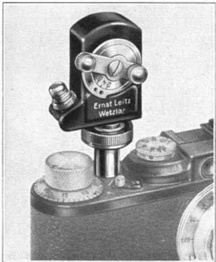
Fig. 48
The button should be depressed until the shutter remove the finger before, or
With older cameras the height of the release button varied slightly as compared with the later models, it may happen that when depressing the button of the Slow-speed Attachment the shutter of the camera is not properly released and an adjustment is required.
The hollow shaft which contains the thread to screw the attachment on the release button shows the large head of an adjusting screw. By means of a suitable screwdriver this screw is given a quarter to half a turn right or left, until the proper release is ensured. If the release button of the camera is too low, the adjusting screw of the Attachment does not bear sufficient pressure on it to release the shutter; in this case the screw is turned anti-clockwise. If the button is too high, the rotating levers in the attachment do not work properly, with
the consequence that the shutter opens only half and remains open. In such a case the adjusting screw is turned clockwise. Needless to say, this adjustment, which by the way is quite easy, need only be done once and for one particular camera.
Leitz Supplementary Front Lenses to the Leica Camera
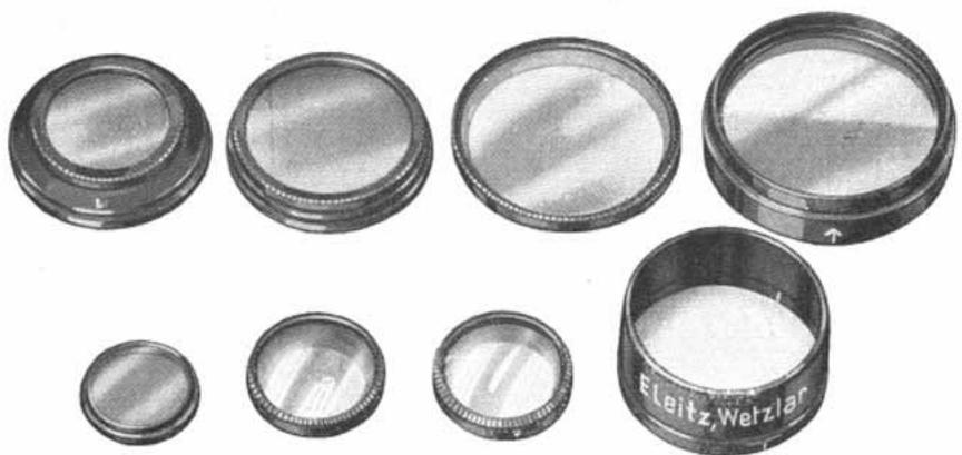
Fig. 49. Yellow Filters, Supplementary Front Lenses, and Lens Hood (half actual size)
These supplementary front lenses are achromatic converging lenses and are used for photographing small living creatures, plants, art objects, etc., at ranges shorter than 3^1/2 ft. as well as for the reproduction of printed matter, illustrations, documents, etc. They screw in the front lens mount of the 5 cm. F/3.5 "Leitz-Elmar" or 5 cm. F/2.5 "Leitz-Hektor" lenses and should only be screwed home moderately firmly.
We supply them in three powers, namely:
No.1 for distances from 39^1 / 2 - 22^9 / 16 ins.
For objects of sizes 16^9 / 16 × 24^13 / 16 ins., to 8^9 / 16 × 12^7 / 8 ins.
For reducing from 17.5 to 9.1 times.
No.2 for distances from 21^9 / 16 - 15^15 / 16 ins.
For objects of sizes 8^7 / 16 × 12^5 / 8 ins., to 5^5 / 8 × 8^1 / 2 ins.
For reducing from 8.9 to 6.0 times.
No.3 for distances from 12^1 / 4 - 10^11 / 16 ins.
For objects of sizes 4^1 / 4 × 6^5 / 16 ins., to 3^3 / 8 × 5 ins.
For reducing from 4.5 to 3.5 times.
The distances are measured from the back of the camera (plane of the film) to the object.
It may be observed here that 5cm lenses of the Leica camera ("Leitz-Elmar", "Leitz-Hektor" and "Leitz-Summar") without supplementary lens render it practicable to take objects at a distance of 3^1/2 ft. and in these circumstances reduce the size of an object measuring 26 × 17^1/4 ins. to one-eighteenth its original size.
By enlarging the negative obtained with the front lens in use, a picture can be made to show the object in natural size and, where the front lens No.3 has been used, it can even be enlarged beyond natural size.
Detailed particulars respecting the setting of the camera lens by its helical focusing mount, the distance and practicable size of the object, as well as the resulting reduction and depth of focus, may be found from the "Tables for Use with the Leica Camera" compiled by us.
The supplementary front lenses Nos. 1 and 2 for the "Leitz-Elmar" lens are available for use at full aperture for snapshots. When using them for copying work they should be stopped down. In particular, it is advisable in the case of the No. 3 front lens always to stop down to at least F/6.3 in view of the very small depth of focus.
The front lenses to the "Leitz-Hektor" 5 cm. lens, however, require a restricted use of the iris diaphragm. For further particulars please refer to the "Tables for Use with the Leica Camera".
The supplementary front lenses to the "Leitz-Hektor" may also be used with an intermediate ring "Vorgi" for the "Leitz-Summar" 5cm lens, while in the same manner the supplementary front lenses to the "Leitz-Elmar" may be used with an intermediate ring "Vmcoo". It is obvious that the somewhat smaller diameter of the "Leitz-Elmar" and "Leitz-Hektor" front lenses necessitates stopping down to a certain extent, but this is in any case advisable in this kind of work.
The exposure is the same, whether one photographs the same object with the "Leitz-Elmar" lens alone at a distance of 3.5 ft. or with a supplementary front lens No.1 at 23^1 / 4 ins., or with the supplementary front lens No.2 at 16^1 / 8 ins. or with the front lens No.3 at 10^11 / 16 ins. To enable one to use yellow filters in conjunction with the front lenses, we supply an intermediate collar ("Firgi").
Particulars of reproduction work, for which the supplementary front lenses are especially well suited, are given in our catalogue on reproduction devices in conjunction with the Leica. Our catalogue "Auxiliary Reproduction Devices" deals at length with the use of these front lenses.
Leitz Yellow and Green Filters
The yellow filters serve to render correctly the colours in conjunction with the more or less sensitized film. For instance, they enable one to capture cloud effects when
The filter factors for the exposure
| Type of film | Sensitivity in Din degree | By sunlight | ||
| Filter No.0 | Filter No.1 | Filter No.2 | ||
| Agfa | ||||
| Leica-Isochrom FF . . . | 10/10 | 1.5 | 1.6...2.4 | 2.0...2.7 |
| Leica-Isochrom F . . . | 16/10 | 1.5 | 1.6...2.4 | 2.0...2.7 |
| Leica-Superpan . . . . . . | 20/10 | 1.2 | 1.3...1.8 | 1.9...2.5 |
| Leica-Finopan FF . . . . . . | 10/10 | 1.2...1.8 | 1.5...2.0 | 1.9...2.5 |
| Leica-Isopan F . . . . . . | 17/10 | 1.6...2.0 | 1.9...2.0 | 1.9...2.5 |
| Gevaert | ||||
| Leica-Special . . . . . . | 9/10 | 1.6...2.0 | 3.0...3.2 | 4.0...8.0 |
| Leica-Express-Super-chrom . . . . . . | 13/10 | 1.7...2.5 | 2.5...4.0 | 4.0...9.0 |
| Leica-Panchromosa . . . . . . | 15/10 | 2.0 | 2.0 | 2.5...3.2 |
| Hauff | ||||
| Leica-Special-Feinkorn . . . . . . | 11/10 | 1.3...1.8 | 1.7...2.5 | 2.5...5.0 |
| Leica-Ultra . . . . . . | 14/10 | 1.3...1.9 | 2...3 | 2.8...5.0 |
| Kodak | ||||
| Leica-Panatomic . . . . . . | 15/10 | 1.2 | 1.3...1.8 | 1.6...2.0 |
| Leica-Supersensitive (SS) . . . . . . | 16/10 | 1.2 | 1.2...1.8 | 1.6...2.0 |
| Mimosa | ||||
| Leica-Extrema . . . . . . | 18/10 | 1.3...2.0 | 2.7...4.0 | 3.1...6.3 |
| Perutz | ||||
| Leica-Spezial-Antihalo . . . . . . | 12/10 | 1.3...2.2 | 2.0...3.2 | 2.5...3.5 |
| Leica-Neopersenso . . . . . . | 14/10 | 1.7...2.0 | 2.2...3.2 | 3.1...5.0 |
| Leica-Rectepan . . . . . . | 10/10 | 1.6...2.0 | 2.2...2.5 | 2.6...4.0 |
| Leica-Perpantic . . . . . . | 15/10 | 1.6...2.0 | 2.0...2.5 | 2.5...3.5 |
| Leica-Peromnia . . . . . . | 17/10 | 1.6...2.0 | 1.9...2.5 | 2.5 |
- The values have been computed afresh by ourselves. The latitude between the figures given in the table is due to the various factors which affect the time of exposure, e.g. composition of the light, variations in the emulsion, mode of development, etc.
for the Leica Camera*
photographing landscapes. The filter factor for the exposure becomes less in proportion to the degree of sensitivity of the film.
are approximately as follows:
| By sunlight | By artificial light | |||||
| Greenfilter | U.-V. Filter | Filter No. 0 | Filter No. 1 | Filter No. 2 | Greenfilter | U.-V. Filter |
| 2.5...3.2 | 1.1 | 1.2...1.8 | 1.3...1.8 | 1.3...2.0 | 1.1 | |
| 1.1 | 1.2...1.8 | 1.3...1.8 | 1.3...2.0 | 1.1 | ||
| 1.2 | 1.1 | 1.3 | 1.5...1.8 | 1.9...2.0 | 1.2 | |
| 1.9...2.5 | 1.5...1.8 | 1.3...1.8 | 1.7...1.8 | 1.5...1.8 | 1.9...2.5 | 1.3...1.9 |
| 1.7...2.5 | 2.0 | 1.1 | 1.2...1.8 | 1.3...1.8 | 1.6...2.3 | 1.7 |
| 2.5...3.2 | 1.6...2.0 | 1.6...2.0 | 2.0...2.5 | 2.5...3.2 | 1.6...2.0 | |
| 1.6...2.0 | 1.6...2.0 | 1.6...2.5 | 3.1...3.9 | 1.2...1.8 | ||
| 2.0 | 1.3 | 1.6 | 1.6...2.0 | 1.6...2.0 | 1.3 | |
| 1.6...2.0 | 1.9...2.0 | 1.9...2.5 | 2.5...4.0 | 1.6...2.0 | ||
| 1.6...2.0 | 1.5...2.0 | 1.8...2.5 | 2.5...3.8 | 1.4...2.0 | ||
| 1.6...2.5 | 1.2 | 1.1 | 1.2...1.3 | 1.6...1.8 | 1.6...2.0 | 1.2 |
| 1.9...3.2 | 1.2 | 1.2 | 1.1...1.3 | 1.2...1.8 | 1.9...2.5 | 1.2...1.3 |
| 2.2...5.0 | 1.6...2.0 | 1.3...2.0 | 1.7...2.5 | 2.5...3.2 | 1.3...2.0 | |
| 1.6...2.2 | 1.1 | 1.2...1.8 | 2.2...2.5 | 1.1 | ||
| 1.6...2.5 | 1.2...1.8 | 1.6...2.5 | 1.6...2.5 | 1.2...1.8 | ||
| 2.3...4.0 | 1.6...2.0 | 1.1 | 1.2...1.6 | 1.3...1.8 | 1.9...3.1 | 1.1 |
| 2.5...3.9 | 1.7...2.3 | 1.3...1.6 | 1.4...1.8 | 1.4...2.0 | 2.0...2.7 | 1.2...1.6 |
| 1.8...2.5 | 1.2...1.8 | 1.6...1.8 | 1.6...2.0 | 2.2...2.5 | 1.2...1.7 | |
The figures given in the table under "Sunlight" factors are correct for white light, e.g. blue sky with white clouds. The exposure should be increased by approximately one half when the light is dark blue, e.g. in summer from about 11 a.m. to 2 p.m. (blue sky without any noteworthy clouds).
The use of dense (i.e. dark) filters is not to be recommended, since they cause blue to appear too dark and green and yellow too light. In practical photography, such photographs have a pronouncedly overfiltered and consequently unnatural appearance. Care must always be taken to choose the density of the filter one uses so that it may suit the subject, the film material, the time of day and the illumination. This method will be found to give the best results as far as the correct rendering of colours is concerned. It should be noted that,
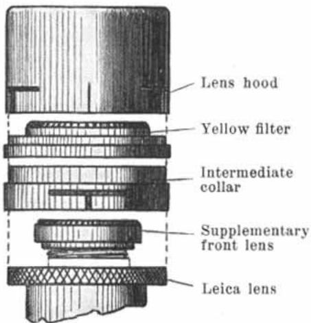
Fig. 51. How to use the various front attachments (two-thirds actual size)
according as the film is more correctly sensitised as to colour rendering, the filter in use can be correspondingly lighter; for instance, a lighter filter will be used with panchromatic film than with orthochromatic film and in the same way, a lighter filter will be chosen for the latter when it is sensitised more especially for yellow-green. Another factor to be borne in mind is that in the morning and evening the light from the sky contains a greater proportion of yellow rays and only little violet light, so that at these times a lighter filter or even no filter at all should be used. In the middle of the day, on the contrary, the light is bluer and necessitates a somewhat denser filter. In the same manner, a deep blue sky necessitates a denser filter than a sky with highly reflecting white clouds.
There is, however, yet another reason why one should abstain from the use of too dense a filter, besides the effect of over-filtration referred to above. In unfavourable circumstances a dense yellow or green filter can impair the absolute sharpness of the negatives, especially in the case of films with a thick coating of emulsion. The plane parallel finish of good filters (which, one might say, is almost carried to excess) certainly obviates a distortion, but the difraction of the light in a thick coating of emulsion cannot fail to cause a slight deterioration in the sharpness if the blue rays are disproportionately cut out. This is due to the fact that the short wave blue and violet rays form the image on the surface of the emulsion; they hardly penetrate the interior of the emulsion and can consequently not be diffused. Rays of longer wavelength (yellow and above all red rays) penetrate on the other hand comparatively far into the emulsion and suffer diffraction; this diffraction increases proportionately to the depth of the emulsion. The surface image is in consequence somewhat impaired in its sharpness by this diffused image formed inside the emulsion. The denser the yellow filter or the green filter, the more blue rays are cut out, and other things being equal, the greater is the loss in sharpness.
This loss of sharpness must of course not be exaggerated. It can in fact be completely overlooked in the case of films having a very thin coating of emulsion.
For use with the Leica camera with focal plane shutter the yellow filters are usually supplied in slip-on mounts. Fig.51 shows how they are attached, either alone or in conjunction with a supplementary front lens or lens hood. For the simultaneous use of a supplementary front lens and a yellow filter an intermediate ring is required ("Firgi").
If desired, yellow filters can be supplied in screw-in mounts for use with the focal plane shutter camera. The iris diaphragm in this case is actuated directly, but the yellow filter cannot then be used in combination with the front lens.
For the two lenses "Leitz-Elmar" F/4.5, 13.5 cm. focal length, and "Leitz-Hektor" F/2.5, 5 cm. focal length, the filters are supplied in slip-on mounts only (see Leica catalogue).
The Graduated Yellow Filter. When photographing scenes with a particularly bright background and a dark foreground, we recommend using the graduated yellow filter to avoid partial over-exposure. This filter is supplied in a fixed slip-on mount to fit all Leica cameras having a focal-plane shutter. The dividing line of the filter is in the centre. Care must always be taken to ensure that the arrow engraved on the outer edge of the mount lies on top. The filter doubles normal time of exposure.
Vice versa the graduated yellow filter can also be used for scenes with a particularly bright foreground (snow scenes etc.). In this case the arrow engraved on the mount must lie underneath.
Green filter. All panchromatic negative material to be had on the market and destined for use with the Leica presents a gap in the scale of reproduction in the green section of the spectrum as compared to its sensitivity to red and blue-violet. A suitable green filter remedies this defect. The filter factors for our green filter are given in the table on Pages 58 and 59.
The new panchromatic films with reduced sensitivity to red necessitate a filter which transmits chiefly yellow and green; our yellow filter No. 0 may be used for this purpose.
Red filters. They are used in conjunction with infra-red film, which is also sensitive to infra-red rays in addition to the range of a visible spectrum. The use of this filter allows only the visible red and a portion of the (invisible) infra-red rays to be used for the formation of the image, since it absorbs yellow, green and blue almost entirely. The peculiar effect of these infra-red photographs is of less importance for general amateur photography than for special scientific purposes.
For example, it is possible with the help of infra-red photography to obtain clear photographs of mountains, scenery or towns through the mist and fog present in the atmosphere; this is of special importance in the case of aerial photography. In every case, however, the infra-red photograph differs to a greater or a lesser degree from the image seen with the naked eye.
When the sky is clear and the sun is shining brightly, the red filter causes the blue of the sky to appear black; objects in the scenery (foliage and buildings) reflect the infrared rays strongly and consequently appear bright in the picture. Taken together, the general effect is one of a night photograph. It is, however, not exactly similar to a night photograph, in that the latter would cause the landscape to appear dark.
A correct use of infra-red film can, however, be of advantage for reproducing certain features of anatomical specimens, reproductions of paintings, etc.
The helical focusing mounts of all Leica lenses now bear a second index mark, indicated by R, which serves for focusing when taking infra-red photographs. The object is focused differently according to whether the lens is coupled with the rangefinder (Leicas II and III, Leica 250) or not (Leica I and "Standard"). When the lens is not coupled with the rangefinder the distance is read off on the rangefinder scale and the lens set to that distance by means of the index R. When the lens is coupled and in the case of the accessory for single
exposures ("Oleyo", "Oligo"), the lens is first focused in the usual manner, then the helical mount extended until the index R points to that position on the scale which was first indicated by the main index.
In the case of lenses of less recent manufacture which have as yet no second index line, instead of using the main index line for setting the lens, one takes the diaphragm stop index given in the following table for each individual objective. Since each of these diaphragm stops is marked twice on the depth of focus ring it should be added that the one used in this case is that nearer to the infinity () mark.
Infra-Red Photographs with the Red Filter
| Lens | Instead of the main index line, use the following line on the depth of focus ring | |
| Leitz-Elmar | 3.5 cm. | 11/2mm.* |
| Leitz-Elmar | 5 cm. | 6.3 towards∞ |
| Leitz-Hektor | 5 cm. | 6.3 ,,∞ |
| Leitz-Summar | 5 cm. | 2 ,,∞ |
| Leitz-Hektor | 7.3 cm. | 4.5 ,,∞ |
| Leitz-Elmar | 9 cm. | 6.3 ,,∞ |
| Leitz-Elmar | 10.5 cm. | 9 ,,∞ |
| Leitz-Elmar | 13.5 cm. | 6.3 ,,∞ |
| Leitz-Hektor | 13.5 cm. | 6.3 ,,∞ |
The method is the following (taking for example the 5 cm "Leitz-Elmar"):
First ascertain the distance by means of the rangefinder, e.g. 15 ft. Then rotate the helical mount of the 5cm . "Leitz-Elmar" in such a way, that instead of the main index line, the depth of focus index 6.3 situated nearer the mark points to 15 ft. The exposure may then be made. In the event of the distance measured being , then the lens is not completely rotated up to the stop when the index 6.3 points to .
If particular emphasis is laid on sharpness when taking infra-red photographs, it is generally advisable to stop down. This depends particularly on the way in which the image is formed in the emulsion. There is obviously no limit to the amount of stopping down except when time exposures are to be avoided.
It should be observed that when using the red filter, the exposure time which varies within wide limits is at least ten times and often fifty to a hundred times as long as when using a film of 8 / 10^ Din.
Since infra-red film has a fairly coarse grain, it should be developed 10 minutes with Agfa Final Developer or 10 to 12 minutes with Hauff Microlin Developer. Longer developing times should be avoided to prevent the grain becoming still more apparent.
U-V protective filter. For taking photographs at high altitudes (about 6,500 ft.) the customary yellow filters are not so well suited, because they absorb completely the light preponderant at these heights, namely blue, violet and ultraviolet. (The sky appears black.)
We recommend in these cases the use of our U-V protective filter, which, as its name implies, absorbs ultra-violet light, but not all the blue and violet light. As a result, the sky appears in its natural tone. The exposure time as compared with photographs taken without a filter is shown in a table on pages 58 and 59. As at such heights the time of exposure generally required is only half that needed at lower altitudes, the exposure with the ultra-violet filter will be about the same at above 6,500 ft. as down below when working without this filter.
The lens hood (Fig. 52) which is fixed over the front mount of the lens is used when photographing obliquely against the sun, in order to prevent as far as possible direct rays from entering the lens and setting up unwanted reflections. It is supplied in three models. The first model is of fixed length and intended for use with the "Leitz-Elmar" 5cm lens. The second is similar to the first, but shorter and destined for use with the 3.5cm wide angle "Leitz-Elmar" lens. The third
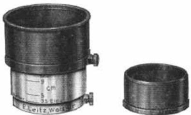
Fig. 52. The lens hoods
model has an extensible tube which may be altered so as to suit the various focal lengths. Placed on the lens mount, it is fixed like the other two by means of a clamping screw. Its extension may also be clamped in the desired position by means of a screw.
Leitz Panoramic Tripod Head with interchangeable scale rings
The Panoramic Tripod Head makes it possible to take composite pictures of a panorama up to a complete revolution, whether in upright or in horizontal pictures. The scale ring of the Panoramic Tripod Head is interchangeable and can be supplied to suit the focal length of any Leica lens.
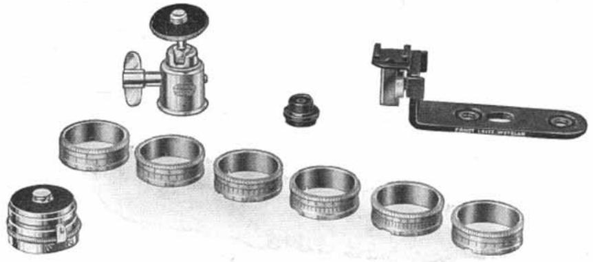
Fig. 53. Ball-jointed tripod head, case level, angular bracket, panoramic tripod head and interchangeable scale rings
Any strongly built tripod can be used for taking panoramic photographs with the Leica. It is better not to screw the panoramic tripod head straight on to the tripod, but rather on to a ball jointed tripod head, so that the camera may more easily be set absolutely horizontally. The first thing is to set the camera and consequently the optical axis of the lens in a strictly horizontal plane. The case level which serves to control this position (Doolu) is slipped into the clamp on the angular bracket. After the camera has been set exactly horizontal, the first exposure is taken with the panoramic tripod head set to the index 1, wherupon the camera is carefully rotated until the snap catch engages in the mark engraved 2. In this position, the second exposure is made, and so on. It should be noted that the scaled ring is engraved with two rows of figures. The upper row serves when taking upright photographs and the lower one when taking horizontal photographs.
The scaled rings are exchanged in the following manner:
When the snap catch has caught in the position corresponding to the mark 1, the lower plane milled portion of the head is held in the right hand and the scaled ring simply removed with the left hand.
The new ring is inserted so that the snap catch slips over the notch in the ring at the mark 1. Should the spring not catch perfectly in this position, then the lower milled ring on the panoramic tripod head itself is turned until the scaled ring can be completely pushed down. When this happens, two fixing pins provided for this purpose catch in two notches in the ring.
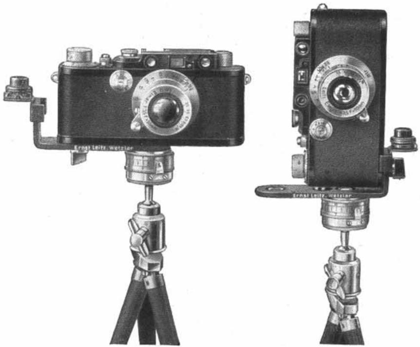
Fig. 54. Arrangement for horizontal Fig. 55. Arrangement for photographs upright photographs
In order to relieve the strain on the lid of the Leica when taking panoramic photographs with the heavy long focus lenses, we recommend the use of the special fixing cap "Vesuk". In the case of the "Leitz-Elmar" or "Leitz-Hektor" 13.5cm lenses the panoramic tripod head is screwed in to the tripod thread on the lens mount itself. In this case, neither the fixing cap nor the angular bracket are necessary.
The case level (Fig. 53) is required for taking panoramic views and its use is also recommended for architectural subjects.
It slips into the rangefinder clip provided in top of the camera.
The ball jointed tripod head (Fig. 56) is also used for taking panoramic views and in addition is required for all upright photographs taken on a tripod, as the camera has a tripod thread only for horizontal photographs. It is best used together with the angular bracket, particularly for architectural work, when the case level also should be employed.
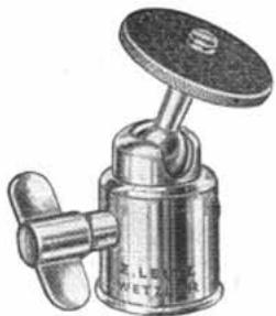
Fig. 56. Ball-jointed tripod head, approximately one half actual size.
Tripod head with press catch. To enable one to fix the Leica and to remove it very quickly from a tripod, use may be made of our tripod head with press catch. The lower part of this tripod head is screwed on to the tripod while the upper portion is screwed into the tripod thread of the Leica. When both parts are pushed together, a firm connection is established between the camera and the tripod. When removing the
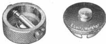
Fig. 57
camera from the tripod, the two lateral knobs are pressed together, wherupon both halves may be taken apart without difficulty.
The Stereo-slide is screwed on the tripod, and enables the camera to be shifted laterally, so that the two relative stereo exposures may be made shortly after each other. It is, of course, only possible to make exposures of still objects. The slider which carries the camera may be secured in any position. Generally a lateral displacement of 65 - 75mm will be preferred. At 75mm the slide is provided with a mark. For distant ex
posures without close foreground the lateral displacement may be extended to 150mm in order to obtain a satisfactory stereoscopic effect.
It should be mentioned that one of the stop screws at the end of the slide has a milled head and may be unscrewed in order to remove the slider and reverse the same. This is necessary as the rotation of the ring plate is not always sufficient to fix the camera in a convenient position. When taking the left
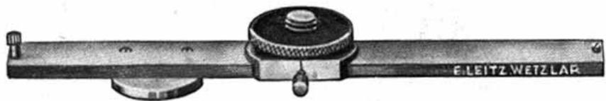
Fig. 58. Stereo Slide (about 1/2 act. size)
component picture the camera projects over the end of the slide, whilst when the right component picture is taken it rests completely on the slide. The ring plate rotates and enables one to clamp the camera exactly in the direction of the slide. Obviously, the correct position of the slider need only be adjusted to the thread of the camera once.
On our Leica Stereo Attachment "Stereoly" we have issued separate literature. Further, there are separate lists on: Leica, the Camera of Modern Times.
The Interchangeable Leica Lenses.
The Leica 250.
Leica Accessories.
The "Standard" Leica.
Reproduction Devices in conjunction with the Leica Camera.
A Chat about the Interchangeable Leica Lenses.
Special Viewfinders for the Leica Camera.
Developing and Copying Apparatus for Leica Films.
Enlarging Apparatus.
Small Projectors.