
4000DS MK-II - Enregistreur analogique AKAI - Notice d'utilisation et mode d'emploi gratuit
Retrouvez gratuitement la notice de l'appareil 4000DS MK-II AKAI au format PDF.
| Type de produit | Enregistreur analogique à bande magnétique 4 pistes stéréo/mono |
| Marque | AKAI |
| Modèle | 4000DS MK-II |
| Dimensions (L x H x P) | 407 x 314 x 196 mm |
| Poids | 11,1 kg |
| Alimentation | 110–240 V CA, 50/60 Hz (selon modèle) ; consommation 40 W |
| Vitesses de bande | 9,5 cm/s (3-3/4 ips) et 19 cm/s (7-1/2 ips) |
| Pleurage et scintillement | < 0,12 % WRMS à 19 cm/s ; < 0,15 % WRMS à 9,5 cm/s |
| Réponse en fréquence | 30 Hz – 23 000 Hz (±3 dB) à 19 cm/s avec bande Akai LN‑150‑7 |
| Distorsion | < 1 % (1 000 Hz, 0 VU) sur bande low noise |
| Rapport signal/bruit | > 56 dB |
| Taux d'effacement | > 70 dB |
| Fréquence de polarisation | 100 kHz |
| Têtes | 3 têtes : lecture (entrefer 1 µm), enregistrement, effacement |
| Moteur | Moteur à induction 4 pôles |
| Entrées | Microphone (2) : 0,55 mV/30 kΩ ; Ligne (2) : 50 mV/200 kΩ ; DIN |
| Sorties | Ligne (2) : 0,775 V/50 kΩ ; Casque (1) : 30 mV/8 Ω |
| Fonctions principales | Arrêt automatique, pause, avance/retour rapide, enregistrement son-sur-son, mixage, sound‑with‑sound, épissage |
| Entretien et nettoyage | Nettoyage régulier des têtes, galet presseur et cabestan avec alcool ou kit Akai HC‑500 ; démagnétisation périodique |
| Sécurité | Arrêt automatique en fin de bande ; ne pas exposer à la pluie ou à l'humidité |
| Pièces détachées et réparabilité | Fusible de rechange fourni (sauf modèles CEE/CSA/UL/LA) ; contacter un centre de service agréé AKAI |
FOIRE AUX QUESTIONS - 4000DS MK-II AKAI
Questions des utilisateurs sur 4000DS MK-II AKAI
0 question sur cet appareil. Repondez a celles que vous connaissez ou posez la votre.
Poser une nouvelle question sur cet appareil
Téléchargez la notice de votre Enregistreur analogique au format PDF gratuitement ! Retrouvez votre notice 4000DS MK-II - AKAI et reprennez votre appareil électronique en main. Sur cette page sont publiés tous les documents nécessaires à l'utilisation de votre appareil 4000DS MK-II de la marque AKAI.
MODE D'EMPLOI 4000DS MK-II AKAI
4000DSMk-Ⅱ
STEREO TAPE DECK
OPERATOR'S MANUAL
WARNING:
To prevent fire or shock hazard, do not expose this appliance to rain or moisture.
CEE, CSA, UL and L.A. Standard models are not equipped with Voltage Selector and Cycle Conversion Switches. Therefore, voltage and cycle conversion is not necessary. If your machine corresponds to any of these standards, please disregard all references to voltage and cycle adjustment throughout this manual.
CEE Models: 220 V, 50 Hz
CSA Models: 120 V, 60 Hz
UL Models : 120 V, 60 Hz
L.A. Models: 120 V, 60 Hz
INDEX
Controls 2
Voltage & Cycle Conversion 4
Tape Speed Selection 4
Automatic Shut-Off 4
Pause Control 4
Fast Forward & Rewind 4
Connections 5
Operating Precautions 6
Head Cleaning 6
Pinch Wheel & Capstan Cleaning 6
Head Demagnetizing 7
Tape Erasing 7
Adjustment of Recording Level 7
Sound Monitoring 7
How To Use The Din Jack 7
Tape Loading 8
4-Trck Stereo Recording System 8
4-Track Monaural Recording System 8
Playback Compatibility 8
Playback Of Pre-Recorded Tape 9
Recording Using Microphones 10
Recording From An External Amplifier 11
Recording From A Tumtable 11
Tape Dubbing 11
Sound-On-Sound Recording 11
Sound Mixing 12
Sound-With-Sound Recording 12
Tape Splicing & Editing 12
Technical Data 13
Standard Accessories 14
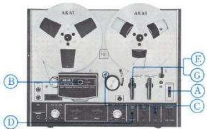
CONTROLS
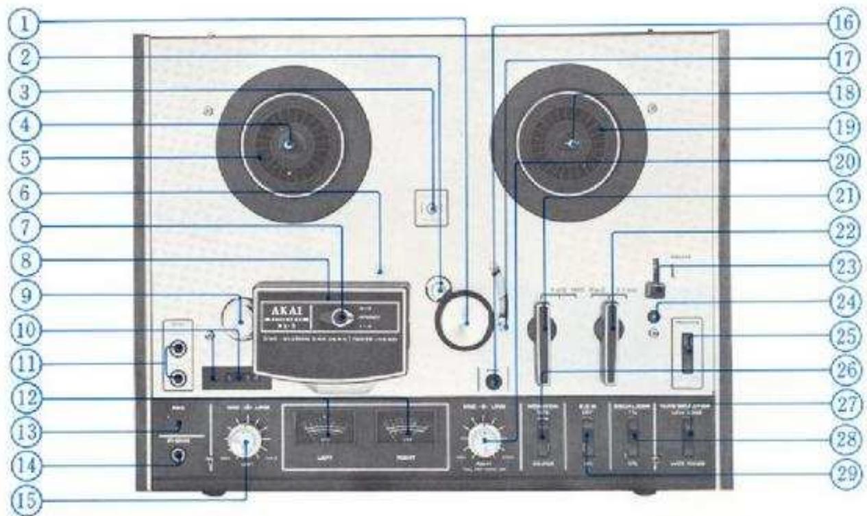
1. PINCH WHEEL
Presses against capstan to transport tape.
2. CAPSTAN
Transports tape and controb tape speed. See Tape Speed Selection procedure.
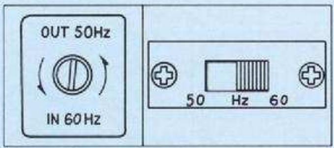
3. CYCLE CONVERSION SWITCH (A)
OUT position 50 Hz, IN position 60 Hz.
4. REEL RETAINER (Left)
Pull outward and turn to left or right to lock reel firmly into place.
5. SUPPLY REEL TABLE
6. CAPSTAN STORAGE POST
7. TRACK SELECTOR SWITCH
For stereo recording/playback set to STEREO position, and for monaural recording/playback set to 3-2 or 1-4 depending upon desired track.
8. HEAD COVER
Houes Erase, Recording, and Playback Heads.
9. TAPE GUIDE
10. INDEX COUNTER & RESET BUTTON
II. MICROPHONE JACKS (Left & Right)
12. VUMETERS (Left & Right)
Indicates recording and playback levels.
13. RECORDING INDICATOR LAMP
Lights when recorder is set to recording mode.
14. HEADPHONE JACK
For monitoring sound or private headphone listening. Use headphones of 8Ω impedance.
15. RECORDING LEVEL CONTROL (Left)
Outer control: Line; Center control: Microphone or Din Jack.
16. RECORDING SAFETY BUTTON
17. SHUT-OFF LEVER
See Automatic Shut-Off procedure.
18. REEL RETAINER (Right)
Pull outward and turn to left or right to lock red firmly into place.
19. TAKE-UP REEL TABLE
20. RECORDING LEVEL CONTROL (Right)
Outer control: Line: Center control: Microphone or Din Jack. (For monaural playback, pull center control outward).
21. RECORD/PLAYBACK LEVER
For playback set to FWD, and for recording set to REC white holding Recording Safety Button at depressed position.
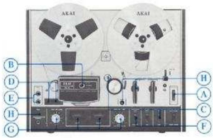
- FAST FORWARD/REWIND LEVER
See Fast Forward & Rewind procedure.
- PAUSE LEVER
See Paine Control procedure.
- START BUTTON
Releasen Pauase Lever.
- POWER/AUTOMATIC SHUT-OFF SWITCH
For turning on power, set to ON position. For automatic Shut-off, see Automatic Shut-Off procedure.
- MONITOR SELECTOR SWITCH (Tape & Source)
During recording mode when the Monitor Selector Switch is set to TAPE position, signals can be monitored as the tape passes the playback head. When set to SOURCE position, the program source will be monitored. For erasing or private listening during playback mode, the Monitor Selector Switch should be at TAPE position.
- TAPE SELECTOR SWITCH
Set to WIDE RANGE or LOW NOISE position according to tape being used. Akai LN-150-7 or scotch #211 tape is considered standard for this machine. In this case, set to LOW NOISE position. Set to WIDE RANGE position only when using special wide range tape of a grade higher than low noise tape.
The use of regular tape is not recommended.
- EQUALIZER SWITCH
Must be set to correspond with tape speed. See Tape Speed Selection procedure.
29.S,O,SSound-On-Sound) BUTTON
See Sound-On-Sound Recording procedure.
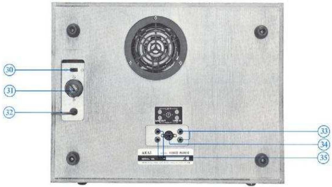
- CYCLE CONVERSION SWITCH (B) (CEE, CSA, UI and LA Models not equipped with this facility)
This Switch and the Cycle Conversion Switch (A) must be set to correspond with area power source.
- UNIVERSAL VOLTAGE SELECTION & FUSE POST (CEE, CSA, UL and LA Models not equipped with this facility) See Voltage & Cycle Conversion procedure.
32.A.C.CORD
33 LINE INPUT JACKS (Left & Right)
Connect to output Jacks of external source.
- DIN JACK
Enables interconnection with an external amplifier with a single Din Cord, Use instead of Rec. and P.D. Jacks.
-
When using the Dina Jack, input level is controlled with Microphone Recording Level Controls.
-
LINE OUTPUT JACKS (Left & Right)
Connect to tape in or aux jacks of external amplifier for playback.
TAPE SPEED SELECTION
This model operates on two tape speeds; i.e., 3-3/4 and 7-1/2 ips. Tape speed is determined by the capstan. The Equalizer must be set accordingly for proper equalization. For 3-3/4 ips remove outer capstan and place on storage post. For 7-1/2 ips use the outer capstan.
Recording Time: (Stereo 1800 ft tape) 3-3/4 ips : 3 hrs., 7-1/2 ips : 1.5 hrs. (Monaural 1800 ft tape) 3-3/4 ips : 6 hrs., 7-1/2 ips : 3 hrs.
AUTOMATIC SHUT-OFF
One of the exclusive features of this model is the automatic shut-off function of the unit. For automatic shut-off, thread tape through Automatic Shut-Off Lever and set Power/Automatic Shut-Off Switch to SHUT-OFF position after setting machine to playback or recording mode. When the tape comes to the end the Shut-Off Lever will drop cutting the power of the entire unit.
VOLTAGE & CYCLE CONVERSION
CEE, CSA, UL and LA Models are not equipped with voltage and cycle conversion apparatus.
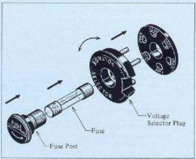
VOLTAGE
Your machine is equipped with a universal voltage selector offering six selections of voltage from 100 V to 240 V AC for worldwide operation. Voltage is preset at the factory according to destination. Please confirm setting prior to operation and if readjustment is necessary, proceed as follows: (A) Disconnect power cord and remove the Fuse Post by screwing in direction of arrow. (B) Remove the Voltage Selector Plug and reinsert so that proper area voltage is shown through the Plug cut-out. (C) Change fuse according to voltage (please refer to supplied fuse tag instructions).
- Be sure to disconnect power cord before attempting to readjust voltage.
To maintain optimum performance and prolong the life of your machine, it is important that the line voltage be held within a 10% deviation of standard area voltage.
CYCLE
Correct tape speed cannot be obtained if the Cycle Conversion Switches are not properly positioned. (A) With a screw driver, turn Swite (A) on face panel counterclockwise about 1/8 of a turn and move to IN or OUT for 60Hz or 50Hz operation according to area power source. The Switch must be rotated back to its original position after being reset. (B) Cycle Conversion Switch (B) at rear of recorder must also be set accordingly.
Do not attempt to rotate the Cycle Conversion Switches when the motor is not running.
PAUSE CONTROL
To momentarily stop the tape during recording or playback, lift Pause Lever upward. Pause Control is especially useful for editing tape during recording. To release Pause Lever depress Start Button.
- Pause control has no effect during fast forward or rewind mode.
FAST FORWARD & REWIND
For, fast forward or rewind, operate Fast Forward or Rewind Lever. This feature permits rapid selection of recordings on the tape. This Lever locks into position and cannot be operated while the Record/Playback Lever is in operation and vice-versa.
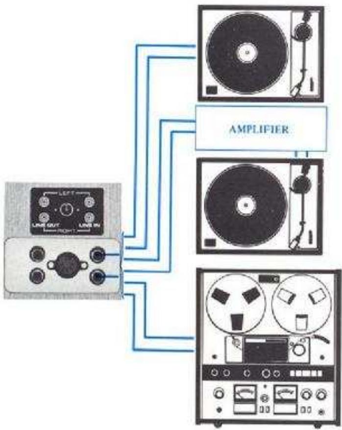
CONNECTIONS


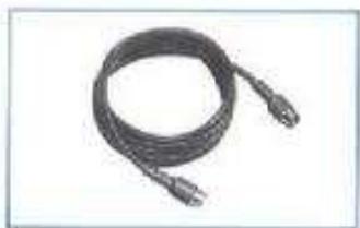
RCA/RCA plug connection cord.
DIN/DIN plug connection cord. Can be used instead of the line jacks to connect with the Din jack of the external amplifier. This enables recording/playback with a single connection cord.
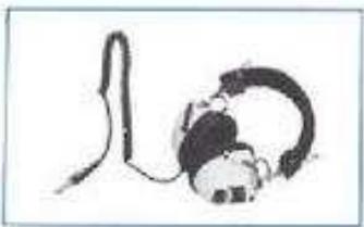
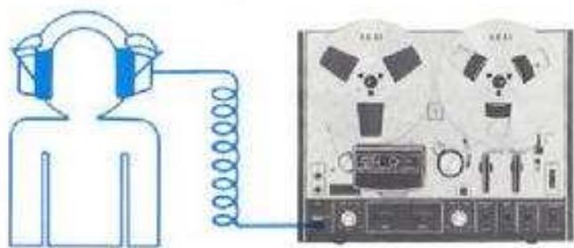
For monitoring or private listening use stereo headphones of 8Ω impedance.
OPERATING PRECAUTIONS
The conditions listed below do not indicate mechanical failure of the unit. If your machine exhibits any of the following, please check for trouble as indicated.
Loss of sensitivity or tone quality may be due to :
- Wrong side of tape facing the heads.
AC power voltage lower than the voltage to which your machine is adjusted. - Dust or magnetic particles adhering to the heads. See head cleaning procedure.
- Magnetized heads. See head demagnetizing procedure.
Defective or worn tape.
Irregularity of tape transport may be due to :
- Dust or magnetic particles adhering to the heads and other parts which the tape contacts. See head cleaning procedure.
- Dirty tape surface or oil adhering to capstan or pinch wheel.
Bent Take-Up Reel. - Tape loaded improperly.
If your machine will not record or playback, check to see that connections are correct and controls are properly positioned.
The following notes are provided for your convenience:
- Your machine requires constant voltage for optimum performance.
If the sound sources are so far away from the microphones that the recording level controls must be turned up to maximum, some hum or noise will inevitably be recorded. A test recording is recommended before attempting a final recording.
Should there be a problem with your machine, write down the model and serial numbers and all pertinent data regarding warranty coverage as well as a clear description of the existing problem and contact your nearest authorized Akai Service Station or the Service Department of Akai Company, Tokyo, Japan.
HEAD CLEANING
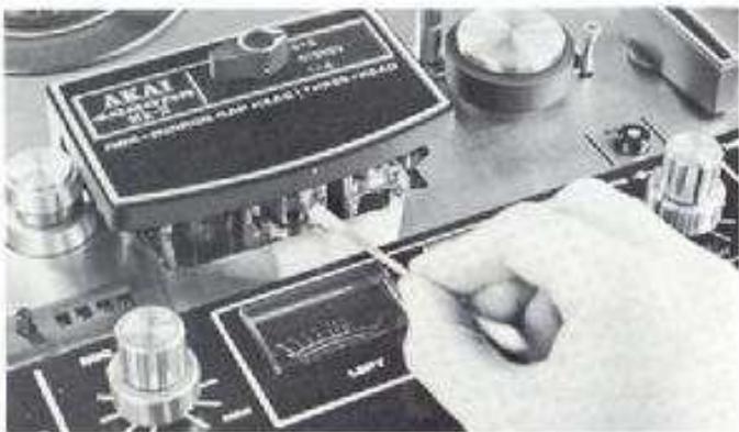
For quality performance, it is imperative that the heads be kept clean at all times. Accumulation of dust and magnetic particles on the heads results in poor head-to-lape contact and deteriorates sound quality and sensitivity. It is, therefore, recommended that the heads be cleaned every time you use your machine. With a stiff cotton swab dipped in Akai Cleaning fluid (Akai Head Cleaning Kit HC-500), rub the entire head surface (do not scratch) until all tape oxide and dust is removed. The capstan shaft, tape lifter, pinch wheel and other parts which the tape contacts should also be cleaned.
* Alcohol can also be used for head cleaning. Do not use chlorothane, etc. as such chemicals will damage the rubber parts.
PINCH WHEEL & CAPSTAN CLEANING
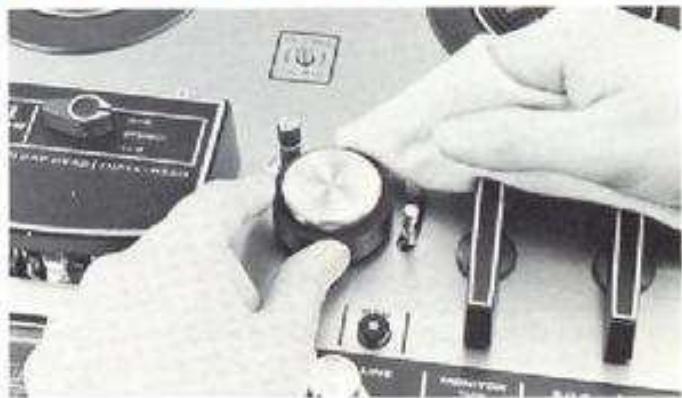
If foreign matter is allowed to accumulate on the pinch wheel and capstan, these particles will come off on the tape, causing deterioration of sound quality. Oil adhering to the capstan also causes irregularity in tape transport. It is, therefore, recommended that these parts be wiped clean periodically.
TAPE ERASING
Any signals previously recorded on the tape will be automatically erased as a new recording is made. For erasing only, set machine to recording mode. No plugs should be connected to the Input Jacks and Volume Controls should be kept at minimum. For quick and complete erasure, the use of a bulk tape eraser is recommended.
- When erasing monaural recorded tape, he sure to set the Track Selector Switch to the track which is to be erased. If set to STEREO position, both tracks will be erased.

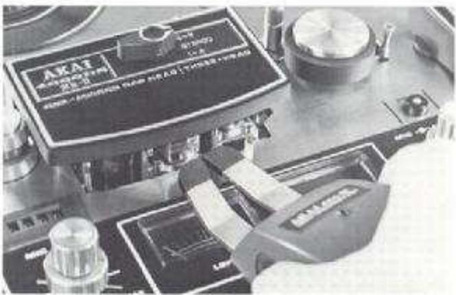
HEAD DEMAGNETIZING
Normally, the steel pole pieces which form part of the recording and playback heads become slightly magnetized. The effect of magnetization is that it causes considerable drop out or introduces noise into your recordings. It is recommended that head demagnetization be performed periodically. This can be accomplished with a bulk head demagnetizer by bringing it very close to the heads and making several small circular motions over the head surface areas as well as the parts which the tape contacts.
- Be sure to cut off the power of the unit prior to demagnetizing the heads.
Both prongs of the demagnetizer should be covered with a kind of masking tape to prevent heads from being scratched.
Do not use magnetized tools in the vicinity of the heads. - Read the instructions of the demagnetizer carefully before operation.
ADJUSTMENT OF RECORDING LEVEL
When the machine is set to recording mode, the recording input levels are registered on the VU Meters, but the recording level can be more precisely set by monitoring through headphones. Adjust Recording Level Controls while monitoring signal strength through headphones. Adjust so that the VU Meters register normally. For recording with the least possible distortion, keep the recording level as high as possible within the yellow part of the meter scale. For monitoring source, set Monitor Switch to TAPE position and for monitoring recorded signals, set to SOURCE position.
SOUND MONITORING
For sound monitoring or private listening, connect stereo headphones of low impedance type (8Ω) to Headphone Jack.
HOW TO USE THE DIN JACK
The Din Jack can be used instead of Rec and P.B. Jacks if your amplifier has a corresponding connection. This one cord system eliminates the necessity of four separate connections and disconnections.
- When using Dim Jack, the recording level is adjusted with the Microphone Recording Level Controls.
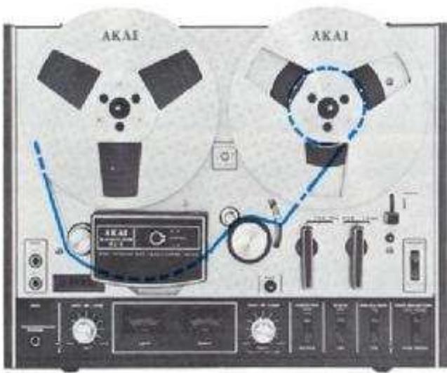
TAPE LOADING
Place a full reel of tape on the Supply Reel Table and an empty reel on the Take-Up Reel Table, and pull built-in reel retainers outward and turn to left or right to lock reels firmly into place. Thread the tape as illustrated by the dotted lines in the figure at left. If automatic shut-off is desired, thread tape through Automatic Shut-Off Lever.
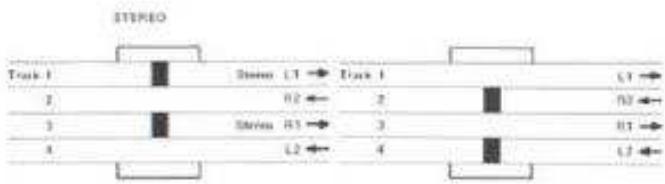
4-TRACK STEREO RECORDING SYSTEM
4-Track stereo recording requires the simultaneous use of two tracks. For stereo operation, set Track Selector to STEREO position. The first recording takes place on tracks 1 and 3, and the second on tracks 2 and 4 after the reels have been inverted.
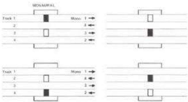
4-TRACK MONAURAL RECORDING SYSTEM
4-Track monaural recording track sequence is 1-4-3-2. For monaural operation, set Track Selector to 1-4. The first recording takes place on track 1 and the second on track 4 after the reels have been inverted. For recording on tracks 3-2, set Track Selector to 3-2. The third recording takes place on track 3 and the fourth on track 4 after the reels have been inverted.
PLAYBACKCOMPATIBILITY
Playback is accomplished through an external amplifier and speakers. Playback sequence and track selection is identical to that outlined in stereo and monaural recording systems above.
PLAYBACK OF PRE-RECORDED TAPE
Please read the operating precautions carefully before attempting operation. Connect the Line Outputs of the 4000DS MARK II to the tape inputs of the external amplifier and connect two speakers to the amplifier. Connect AC cord and load a pre-recorded tape.
STEREO PLAYBACK
A. Turn on Power Switch
B. Set Track Selector to STEREO position
C. Select tape speed and set Equalizer Switch to consistent speed.
D. Set Tape Monitor Switch to TAPE position
E. Set Record/Playback Lever to FWD position to begin playback.
F. Adjust external amplifier controls,
G. To stop playback, return Record/Playback Lever to vertical position.
MONAURAL PLAYBACK
Only the left channel is used for monaural playback. Substitute the following step for step B of stereo playback procedure and add step H.
Tracks 1-4
B. Set Track Selector to 1-4 position
H. Invert reels for playback on track 4.
Tracks 3-2
B. Set Track Selector to 3-2 position
H. Invert reels for playback on track 2.
- When playing back a monaural recorded tape, pull the right channel center recording level control outward.
RECORDING USING MICROPHONES
Please read the operating precautions carefully before attempting operation. Connect AC cord and load a blank new tape.
TAPE SELECTOR SWITCH
This model is equipped with a Tape Selector Switch enabling the use of Low Noise or Wide Range tape. Akai LN-150-7 or scotch #211 tape is considered standard for this machine. In this case, set to LOW NOISE position. Set to WIDE RANGE position only when using special wide range tape of a grade higher than low noise tape. While a superior frequency response covering 23,000 Hz at 7-1/2 ips is attained with low noise tape, this is further extended with the use of wide range tape.
STEREO RECORDING
A. Turn on Power Switch
B. Set Track Selector to STEREO position.
C. Select Tape Speed and set Equalizer switch to consistent speed.
D. With Reset Button, set Index Counter to "0000" position. This Index Counter provides an easy reference for locating positions on the tape.
E. Plug in microphones to Microphone Jacks. Maintain a distance of at least 2 meters (7 ft.) between microphones.
F. Set Monitor Switch to SOURCE position,
G. Adjust and balance microphone input level with Microphone Recording Level Controls while observing VU Meters. Normal recording should not exceed "0" VU on either VU Meter.
H. When an optimum recording level has been determined,
while holding Record Safety Button at depressed position, set Record/Playback Lever to REC position to begin recording. Note that at this time the Recording Indicator Lamp will light.
- To stop recording, return Record/Playback Lever to vertical position.
MONAURAL RECORDING
Only the left channel is used for monaural recording. Substitute the following steps for steps B, E and G of stereo recording procedure and add step J.
Tracks 1-4
B. Set Truck Selector to 1-4 position.
E. Plug in microphone to left Microphone Jack,
G. Adjust and balance microphone input level with left Microphone Recording Level Control while observing left VU Meter.
1. Invert reels to record on track 4.
Tracks 3-2
B. Set Track Selector to 3-2 position.
E. Plug in microphone to left Microphone Jack
G. Adjust and balance microphone input level with left Microphone Recording Level Control while observing left VU Meter.
J. Invert reels to record on track 2.
- Disregard right VU Meter indication when making a monaural recording.
- When monitoring monaural recording through headphones, pull the right channel center recording level control outward.
SOUND-ON-SOUND RECORDING
For transfer of previously recorded material from one track to another accumulating as many individual recordings on a single track as is desired. Use for language training or various interesting musical compilations.
First Recording
A. Turn on Power Switch
B. Confirm that there are no connections to the Line Input Jacks.
C. Set Index Counter to "0000" position
D. Set Track Selector Switch to 1-4 position.
E. Plug in microphone to left Microphone Jack.
F. Set Monitor Selector Switch to SOURCE position.
G. Adjust left Microphone Recording Level Control while observing left VU Meter.
H. While holding Recording Safety Button at depressed position, set Record/Playback Lever to REC position to begin first recording, i.e., DO-RE-ML.
1. When the first recording is complete, rewind tape to starting point.
RECORDING FROM AN EXTERNAL AMPLIFIER
If an external amplifier or tuned amplifier is used, connect the tape outputs of the external amplifier to the Line Inputs of the 4000DS MARK II in step E of stereo recording procedure. VU level is controlled with the Line Recording Level Controls.
- If the Din Jack is used for this connection, VU level is controlled with the Microphone Recording Level Controls.
RECORDING FROM A TURNTABLE
To record from a stereo or monunral disc, a crystal or ceramic pick-up can be connected directly to the Line Inputs instead of step E of recording procedure. However, if magnetic or similar cartridges are used, connect to the Line Inputs of the 4000DS MARK II through an external amplifier.
TAPE DUBBING
When tape duplication is desired, connect the Line Outputs of your 4000DS MARK II to the line inputs of the recording machine instead of step E of recording procedure.
Second Recording
J. Set S.O.S. Switch to ON position.
K. Set Track Selector Switch to 3-2 position.
L. Increase left Line Recording Level Control to maximum level.
M. Connect stereo headphones to monitor first recording on track 2.
N. While holding Recording Safety Button at depressed position, set Record/Playback Lever to REC position to begin second recording; i.e., MI-FA-SOL. The first recording is heard through headphones.
O. Reset left Microphone Recording Level Control until proper level is obtained while observing VU Meter.
The second recording MI-FA-SOL is made on track 3 as the first recording DO-RE-MI is heard through headphones. The two recordings will be completely merged on track 3, i.e., DO-MI-RE-FA-MI-SOL.
The third and subsequent recordings are made in the same manner as the second by switching Track Selector Switch to and from 1-4, 3-2.
* For playback, set Track Selector to track on which the last recording was made. Then set Monitor Switch to TAPE position and pull the right channel center recording level control outward.
SOUND MIXING
For mixing microphone and line input signals, proceed as follows:
A. Plug in microphone to Microphone Jacks and connect line outputs of external source to the Line Input Jacks of the 4000DS MARK II.
B. Adjust microphone volume level with Microphone Recording Level Controls and line input level with Line Recording Level Controls.
C. For playback, operate Track Selector Switch according to tracks used in making recording.
* Mixing can also be accomplished by using the Din Jack and Line Input Jack simultaneously. In this case, the Din Jack input is controlled with Microphone Recording Level Controls.

SOUND-WITH-SOUND RECORDING
This feature is especially convenient for teacher/student repetition and comparison (teacher's voice on track 1, student's voice on track 3) when studying languages.
A. Turn on Power Switch
B. Confirm that there are no connections to the Line Input Jacks.
C. Set Index Counter to "0000" position.
D. Set Track Selector Switch to 1-4 position.
E. Plug in microphone to left Microphone Jack.
F. Set Monitor Selector Switch to SOURCE position.
G. Adjust left Microphone Recording Level Control while observing left VU Meter.
H. While holding Recording Safety Button at depressed position, set Record/Playback Lever to REC position to begin first recording; i.e., A-B-C-D...
1. When the first recording is complete, rewind tape to starting point.
1. Set Track Selector Switch to 3-2 position.
K. Set Monitor Selector Switch to TAPE position.
L. Plug in stereo headphones to monitor the first recording on the left channel.
M. While holding the Recording Safety Button at depressed position, set Record/Playback Lever to REC position to begin second recording; i.e., A'B'C'-D'. The first recording will be heard through headphones.
N. After finishing recording, rewind tape to starting position.
O. Set Track Selector Switch to STEREO position.
P. Set Record/Playback Lever to FWD position and run tape for playback.
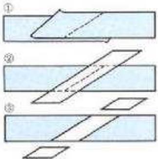
TAPE SPLICING & EDITING
Cut tape diagonally with an overlap so that the ends are lined up. Cutting tape on diagonal eliminates detection of the splice in recording. Cover aligned ends with splicing tape. Press firmly exerting pressure to secure ends evenly. Trim off excess splicing tape cutting into magnetic tape very slightly. This eliminates the possibility of a sticky splice. Splicing tape using scissors requires skillful work. With Akai's specially designed portable Tape Splicer Model AS-3, splicing can be done very smoothly.
TECHNICAL DATA
| Truck System | 4 track, 2 channel stereo/monaural system |
| Reel Capacity | Up to 7" reel |
| Tape Speed | 7-1/2 and 3-3/4 ips (±2%) |
| Wow and Flutter | Less than 0.12% WRMS at 7-1/2 ips; Less than 0.15% WRMS at 3-3/4 ips |
| Frequency Response | 30 Hz to 23,000 Hz (±3 dB) at 7-1/2 ips using AKAI LN-150-7 Tape; 30 Hz to 16,000 Hz (±3 dB) at 3-3/4 ips using AKAI LN-150-7 Tape |
| Distortion | Less than 1% (1,000 Hz "0" VU) using low noise tape |
| Signal-to-Noise Ratio | Better than 56 dB (measured via tape with peak recording level of +6 VU) |
| Erase Ratio | Better than 70 dB |
| Bias Frequency | 100 kHz |
| Heads | (3): 1 one-micron gap playback head, 1 recording head, 1 erase head |
| Motor | 4-pole induction motor |
| Fast Forward and Rewind Time | 200 seconds using a 1200 ft, tape |
| Output Jacks | Line (2): 0.775V ("0" VU). Required load impedance: More than 50 k ohms Phone (1): 30 mV/8 ohms |
| Input Jacks | Microphone (2): 0.55 mV/30 k ohms Line (2): 50 mV/200 k ohms |
| Din Jack | 0.5V/3 mV |
| Semi Conductors | Transistors 19, Diodes 5 |
| Power Requirements | USA and Canada Models: 120 V, 60 Hz only CEE Models: 220V, 50 Hz Other Models: 110 to 240 V, 50/60 Hz (Switchable) |
| Power Consumption | 40 W |
| Dimensions | 407(W) x 314(H) x 196(D) mm (16 x 12.4 x 7.7") |
| Weight | 11.1 kg. (24.4 lbs) |
STANDARD ACCESSORIES
Connection Cord 1
Spare Fuse 1 set
Operator's Manual 1
- Spare fuses are not included with CEE, CSA, UL and L.A. Standard models.

MANUFACTURED & DISTRIBUTED BY
AKAI ELECTRIC CO.,LTD.
AKAI TRADING CO.,LTD.
12.14, 2.chome, Higashi-Kojya
Ohtaku, Tokyo, Japan
AKAI AMERICA, LTD.
2139 E. Del Amo Blvd., Compton, Calif., 80220, U.S.A.
TELEPHONE: (213) 537-3880
TELEX:67-7494
- 4000DSMk-Ⅱ
- WARNING:
- INDEX
- CONTROLS
- PINCH WHEEL
- CAPSTAN
- CYCLE CONVERSION SWITCH (A)
- REEL RETAINER (Left)
- SUPPLY REEL TABLE
- CAPSTAN STORAGE POST
- TRACK SELECTOR SWITCH
- HEAD COVER
- TAPE GUIDE
- INDEX COUNTER & RESET BUTTON
- MICROPHONE JACKS (Left & Right)
- VUMETERS (Left & Right)
- RECORDING INDICATOR LAMP
- HEADPHONE JACK
- RECORDING LEVEL CONTROL (Left)
- RECORDING SAFETY BUTTON
- SHUT-OFF LEVER
- REEL RETAINER (Right)
- TAKE-UP REEL TABLE
- RECORDING LEVEL CONTROL (Right)
- RECORD/PLAYBACK LEVER
- TAPE SPEED SELECTION
- AUTOMATIC SHUT-OFF
- VOLTAGE & CYCLE CONVERSION
- VOLTAGE
- CYCLE
- PAUSE CONTROL
- FAST FORWARD & REWIND
- CONNECTIONS
- OPERATING PRECAUTIONS
- HEAD CLEANING
- PINCH WHEEL & CAPSTAN CLEANING
- TAPE ERASING
- HEAD DEMAGNETIZING
- ADJUSTMENT OF RECORDING LEVEL
- SOUND MONITORING
- HOW TO USE THE DIN JACK
- TAPE LOADING
- 4-TRACK STEREO RECORDING SYSTEM
- 4-TRACK MONAURAL RECORDING SYSTEM
- PLAYBACKCOMPATIBILITY
- PLAYBACK OF PRE-RECORDED TAPE
- STEREO PLAYBACK
- MONAURAL PLAYBACK
- Tracks 1-4
- Tracks 3-2
- RECORDING USING MICROPHONES
- TAPE SELECTOR SWITCH
- STEREO RECORDING
- MONAURAL RECORDING
- SOUND-ON-SOUND RECORDING
- First Recording
- RECORDING FROM AN EXTERNAL AMPLIFIER
- RECORDING FROM A TURNTABLE
- TAPE DUBBING
- Second Recording
- SOUND MIXING
- SOUND-WITH-SOUND RECORDING
- TAPE SPLICING & EDITING
- TECHNICAL DATA
- STANDARD ACCESSORIES
Marque : AKAI
Modèle : 4000DS MK-II
Catégorie : Enregistreur analogique