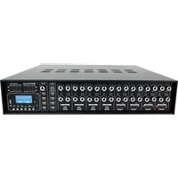
Rock Matrix 4 - Recepteur Rockville - Notice d'utilisation et mode d'emploi gratuit
Retrouvez gratuitement la notice de l'appareil Rock Matrix 4 Rockville au format PDF.


| Type de produit | Récepteur audio/vidéo |
| Marque | Rockville |
| Modèle | Rock Matrix 4 |
| Dimensions (L x H x P) | 430 x 100 x 300 mm |
| Poids | 7 kg |
| Alimentation | 230 V AC, 50 Hz |
| Consommation électrique | 350 W |
| Puissance de sortie | 4 x 100 W RMS (sous 8 ohms) |
| Nombre de canaux | 4 |
| Impédance des haut-parleurs | 4-8 ohms |
| Entrées audio | 3 RCA stéréo, 1 optique, 1 coaxiale |
| Sorties | 4 paires de bornes haut-parleurs, 1 sortie subwoofer |
| Formats audio supportés (USB) | MP3, WMA, WAV, FLAC |
| Connectivité | USB, Bluetooth (optionnel) |
| Fonctions principales | Amplification, sélection de source, contrôle de tonalité, tuner FM |
| Entretien et nettoyage | Nettoyer avec un chiffon doux et sec. Ne pas utiliser de produits chimiques. |
| Sécurité | Ne pas exposer à l'humidité. Débrancher avant nettoyage. |
| Pièces détachées et réparabilité | Contacter le service client Rockville pour les pièces et réparations. |
| Informations générales | Utilisation domestique. Température de fonctionnement : 0-40°C. |
FOIRE AUX QUESTIONS - Rock Matrix 4 Rockville
Questions des utilisateurs sur Rock Matrix 4 Rockville
0 question sur cet appareil. Repondez a celles que vous connaissez ou posez la votre.
Poser une nouvelle question sur cet appareil
Téléchargez la notice de votre Recepteur au format PDF gratuitement ! Retrouvez votre notice Rock Matrix 4 - Rockville et reprennez votre appareil électronique en main. Sur cette page sont publiés tous les documents nécessaires à l'utilisation de votre appareil Rock Matrix 4 de la marque Rockville.
MODE D'EMPLOI Rock Matrix 4 Rockville
ROCKVILLE
ROCK MATRIX 4
4-ZONE 70V COMMERCIAL AMPLIFIER
OWNER'S MANUAL
ATTENTION: WATCH THIS VIDEO BEFORE FIRST USE!

Scan the QR code or go to rockvillesupport.com/rock-matrix-4 for essential information, guides (video and/or written), and tips to make the most out of your purchase.
If you prefer written instructions, please read ahead!
With Rockville you get many options.
Missing items? If you ordered a bundle that includes more than one product and you are missing part of your bundle then it just means your order shipped from two different warehouses. You will receive the remaining items very soon. If you have any concerns or inquiries, feel free to call our customer support center at 1-646-758-0144, 24 hours a day/7 days a week.
Thank you for purchasing this Rockville product. Please read this installation guide carefully for proper use of your Rockville ROCKMATRIX 4 4-Zone 70 Volt Commercial Amplifier. Should you need assistance, please call our technical help line at 1-646-758-0144, 24 hours a day/7 days a week.
Includes
- Remote
- Detachable rack mount ears
- Power cable
- Owner's manual
- Video Card
IMPORTANT SAFETY INSTRUCTIONS

TO REDUCE THE RISK OF ELECTRICAL SHOCK, NEVER OPEN THE UNIT. NO USER SERVICEABLE PARTS INSIDE. WE RECOMMEND SENDING THE UNIT TO THE ROCKVILLE SERVICE CENTER FOR ANY REPAIRS.
- Do not expose this unit to any kind of moisture.
- Please ensure that the unit is situated in a properly ventilated area.
- Do not attempt to operate this unit if the power cord has been frayed or broken.
- Do not attempt to break off or remove the ground prong. This prong is used to reduce the risk of electrical shock and fire in case of an internal short.
- Do not operate this unit if it is damaged.
• This unit is intended for indoor use only. - During long periods of non-use, disconnect the unit from power source.
• Always mount this unit in a safe and stable manner. - Power supply cords should be routed so that they are not likely to be walked on or pinched by items placed upon or against them, paying particular attention to the point of exit from the unit.
• To avoid unnecessary wear and to improve the unit's lifespan, unplug the unit when not in use for extended periods of time.
Introduction
The ROCKMATRIX 4 is a 440-Watt 4-zone rack mountable digital hybrid amplifier/receiver. This amplifier is capable of 70-volt, 100-volt, 16-ohm, 8-ohm, and 4-ohm applications. This makes it perfect for use in a restaurant/bar/café/lounge/school/conference room or any other setting where many speakers are needed.
This 4 zone commercial amplifier allows you to route any source to specific zone(s) and also route any microphone input to specific zone(s). For example you can play Bluetooth on zones 1 and 2 and route microphone 1 to zones 1 and 2 while playing something in Zone 3 using an RCA input, and playing something else in zone 4 using the 1/4 " input. You can also route the other mic input to whichever zones you want.
Each zone has 5 sets of speaker terminals depending on what kind of speakers you have. You can use 70 volt, 100 volt, 16 ohm, 8 ohm, and 4 ohm. No matter what you will get 110 watts RMS per channel. That is 440 watts of total RMS power. For example you can have two 8 ohm speakers on zone 1, thirty 70 volt speakers on zone 2, 16 ohm speakers on zone 3, etc.
This model gives you Bluetooth, USB, SD, two sets of RCA AUX inputs, four XLR mic inputs, two 1/4" TRS inputs, four 1/4" TRS LINE outputs (one per zone), a fire input, and a siren input. There is also a backup DC24V power input in case of a power outage.
The controls are really easy to use. You can easily route any source to any zone(s) and select the volume levels for that zone. There are bass and treble EQ controls to customize the sound. There is also a built-in 1 watt speaker that allows you to drop in onto any zone and listen to the music playing.
The built-in clipping limiter function protects your speakers and the amp from overheating. For further protection there is also a cooling system in this amplifier that will keep the components running cool making the amplifier durable and reliable. There is a fire input and a siren input. This allows you to easily integrate a fire alarm and play a pre-recorded message that will override any music playing in case of an emergency. There is also a backup DC24V power input that allows you to connect a backup 24V battery that will kick in and power the unit in case of a power outage.
What is 70 Volt?
70-volt systems are the number one choice for any application where you want to install multiple speakers. With 70 volt there are a lot of advantages over 8-ohm systems. One of the main advantages is the simplicity of the wiring as well as how easy it is to match up speakers with the amplifier. For example, with this 440-watt/70-volt amplifier, you can install speakers that total close to 380 watts. It does not matter if it is 12 speakers that are 25 watts each or 35 speakers that are tapped at 10 watts each. You always want your 70 volt amp to have at least 15 or 20% more power than the combined watts your speakers are tapped at. When we say the word tap, what we are referring to are the selectors that many speakers in 70 volt have on them. For example, some speakers might have selectable options of 1.5w, 3w, 5w, 10w. What this does is limit how many watts the built-in transformer on the speaker will allow the speaker to get from the amplifier. What this allows for is full customization of your sound for your space. In a restaurant, for example, you can tap your dining room speakers at 5 watts, the speakers by the bar area at 10 watts, the ones in the hallway at 3 watts, and the speakers in the bathrooms at 1.5 watts. Another great feature with 70 volt is you can mix and match any 70-volt speakers whether they are ceiling speakers, wall mounted speakers, subwoofers, etc.
70-volt systems allow you to run very long lines of speaker wire without signal loss. This makes it ideal when running long speaker leads.
The wiring is simple. You just wire all the positive terminals of the speakers to the positive 70-volt terminals of the amplifier. The negative terminals on the speaker simply get wired to the negative terminals on the amp. You do not have to worry about impedance. The power is constant.
Functions
Input Channels
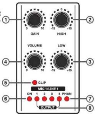
- GAIN: the GAIN knob on each input channel establishes the nominal operating level for the channel. The input gain can be adjusted over a wide range to compensate for soft voice or very loud drum. To maximize the signal-to-noise ratio, the gain should be set to proper level.
- HIGH: an active tone control that varies the high frequency level ±15dB. The center setting frequency is 10kHz.
- LOW: an active tone control that varies the low frequency level ±15dB. The center setting frequency is 100kHz.
- VOLUME: controls the channel output volume level.
- CLIP: the LED indicates if clipping is occurring.
- ON: the LED indicates that the channel is active.
- PHAN (CH1 and CH2 only): the LED indicates that phantom power is on.
- OUTPUT: the LEDs indicate which output channels are active.
Output Channels
- HIGH: an active tone control that varies the high frequency level ±15dB. The center setting frequency is 10kHz.
- MID: an active tone control that varies the mid frequency level ±15dB. The center setting frequency is 1kHz.
- LOW: an active tone control that varies the low frequency level ±15dB. The center setting frequency is 100kHz.
- VOLUME: controls the channel output volume level.
- MUTE: press to mute the channel's signal.

Functions (continued)
Input/Output Selectors
- INPUT: this button is used to select one of the four input channels. Press once to select CH1, press twice to select CH2, press three times to select CH3, press four times to select CH4.
- OUTPUT: these buttons are used to turn the output channels on or off. Press the button once to turn on the corresponding channel, press it again to turn the channel off.
MONITOR
- VOLUME: controls the output level of the channel being monitored.
- OUT buttons: press these buttons to select the channel to be monitored.
- These four LEDs monitor the output level of the corresponding channel.
- LIMIT: this LED indicates that the channel signal is too high.
- FAULT: this LED indicates that a fault has occurred.
MP3 Module
- Display screen
- SD input
- USB input
- MODE: press this button to change input mode (USB/SD or Bluetooth). Press and hold for standby mode.
- PLAY/PAUSE: Press to start playback, press again to pause.
- FOLDER: in USB/SD mode, press this button to display the folder menu. Use the PREVIOUS/NEXT to navigate the files in the folder.
- REPEAT: press once to repeat the current track, twice to repeat all tracks, three times to exit repeat mode. Press and hold for 5 seconds to force disconnect any paired BT device.
- PREVIOUS/◄: in USB/SD mode, press to select previous track, press and hold to rewind. In BT mode, press and hold to adjust volume.
- NEXT/▶: in USB/SD mode, press to select next track, press and hold to fastforward. In BT mode, press and hold to adjust volume.


- Power switch
- DC Fuse compartment
- The green siren connector is used to connect a siren switch. If the siren switch is turned on, the signal will be sent the ROCKMATRIX via the 1/4 " FIRE IN jack.
- XLR Mic inputs
- ¼" LINE IN (CH1 and CH2): use these jacks to connect line level devices.
- PRIORITY: when activated the music volume will lower slightly and priority is given to MIC1 input.
- PHANTOM POWER (MIC1 and MIC2 only): press these buttons to activate phantom power when using a condenser microphone. Please note, never plug or unplug a mic when phantom power is engaged. It may cause damage to the mic.
- RCA LINE IN (CH3 and CH4): use these jacks to connect line level devices.
- CH4 input selector: press this button to change CH4's input from the RCA line in jacks to input from the MP3 player.
- 1/4 " OUTPUTS: these jacks send line level signals to other devices.
- Phoenix terminal speaker outputs
Functions (continued)
- DC 24V IN: these screw terminals allow for the unit to be connected to an external 24V power supply. This will allow the device to continue when there is a power outage or an AC power supply is not available.
- Grounding screw (if using a 2 prong electrical outlet)
- IEC power input with user-serviceable fuse
Remote Control
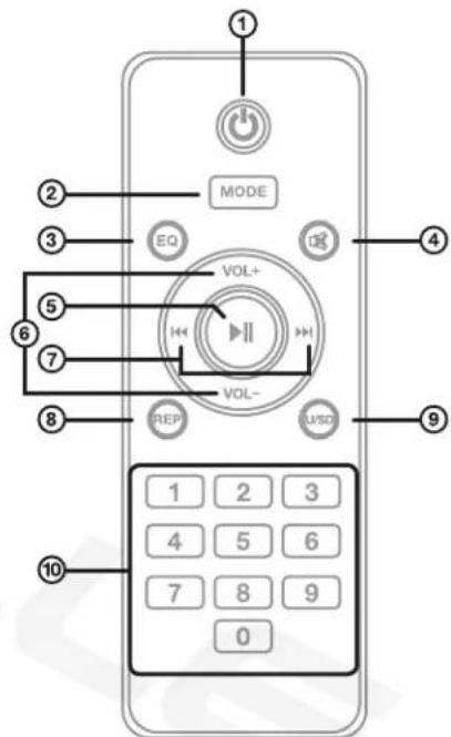
- ON/OFF
- Mode: Switch between SD, USB, and Bluetooth.
- Change preset EQ: Normal, rock, pop, classic, jazz, and country.
- Mute
- Play/Pause: Press to play or pause playback. Press to for two seconds auto-scan and save stations in FM radio mode.
- VOL-/VOL+: Increase or decrease the volume.
- ◀◀ ▶▶: Previous/Next song
- REP: Press once to repeat single track. Press twice to repeat all tracks. Press three times to repeat all files within a folder. Press four times to enter random mode.
- U/SD: Press to switch between USB and SD input.
- Number Pad: Select music files by number.
Setup
Selecting Output Wire and Connectors
It is recommended you use high quality 16 AWG, 2 or 4 conductor, heavy gauge, CL2 or CL3 rated, 100% Oxygen-Free Copper (OFC) speaker wire. CL2 and CL3 ratings refer to the cable jacket's fire resistance and the voltage capacity of the wire. While both cables have the same flame resistance capability, the CL2 cable can handle voltage spikes of up to 150 volts while the CL3 can handle up to 300 volts. When using the 70V/100V speaker output screw connectors, use terminal forks up to 10 AWG (recommended) or bare wire. Below is a chart to help you select the appropriate size wire based on the amp to speaker distance.
| DISTANCE | WIRE GAUGE |
| • Up to 25 ft.• 26ft or more | • 16 AWG• 14 AWG |
CAUTION: Never use shielded cable for output wiring.
CAUTION: For low impedance loads only.
CAUTION: Check local code requirements before installing in-ceiling or in-wall speaker wires. We recommend you use CL2 or CL3 rated, Oxygen-Free Copper speaker wire.
The ROCKMATRIX 4 features four 1/4 line outputs. We recommend you use high-quality Rockville audio cables. Visit RockvilleAudio.com to view our full selection of audio cables.
Selecting Input cables
There are four XLR mic inputs, two 1/4" line inputs, and two RCA line inputs. We recommend you use high-quality Rockville audio cables. Visit RockvilleAudio.com to view our full selection of audio cables.
Rack Mounting
This unit should be on the bottom of the rack or above any equipment that does not produce heat. Be sure to provide at least 1 RU (Rack Unit, 1.75") of space above and below. Preferably, the side wall should be at least 2" from the sides of the amplifier and the back of the rack should be open. This will ensure a source of cool air to all sides of the amplifier.
Connecting Speakers
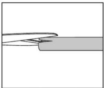
- Carefully cut away a small amount of the speaker wire's insulation.
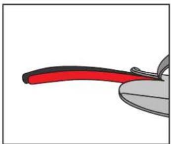
- Peel back enough of the insulation to expose approximately 3 inches of wire.
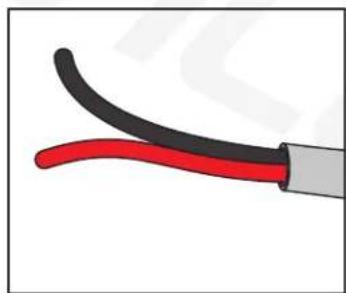
- Cut off the excess insulation.
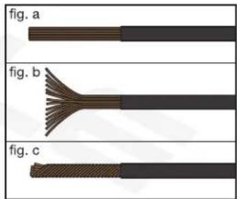
- Strip 1/4" of insulation from each wire (fig. a). Fan out the strands (fig. b) and twist them (fig. c) making sure that there are none sticking out.
Connecting Speakers (continued)

- Loosen the screw on the corresponding male Phoenix terminal block.
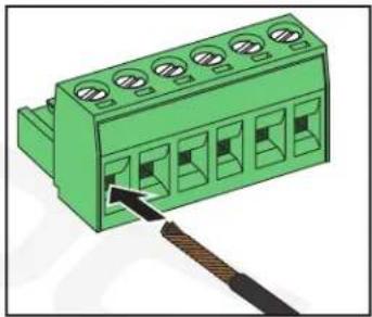
- Insert the appropriate wire into the corresponding slot. Check that the wire is fully inserted and properly seated.
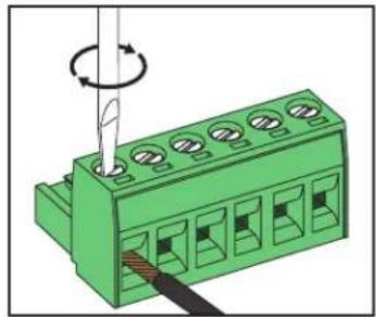
- Tighten the terminal, do not overtighten. Repeat this procedure for the other wire. Make sure you've insert the wires into the correct slots.

- Plug the terminal into the corresponding zone slot. Gently push it until you hear it click. Repeat all the previous steps for the other zones.
Output Configurations
The ROCKMATRIX 4's 70V and 100V connections can be set up in a variety of ways.
Multi-Zone 70V/100V Speaker Output
You may connect any number of 70-volt or 100-volt speakers to each zone as long as the total output for any one zone does not exceed 110 watts and the overall total output of the zones does not exceed 440 watts. As with the direct outputs, best practice is to allow for about 10 – 20% "head room" or extra power. So, the total output power of the speakers connected to any one zone should not exceed 90 – 100 watts, and the total power output of all the zones combined should not exceed 370 – 380 watts.
Multi-Zone Connection Example
In this example we have various 70V speaker combinations (totaling 17 speakers) connected to various zones, none exceeding more than 110 watts per zone and with a total overall zone power rating of 340 watts, well below the maximum total zone power output of 440 watts.
WARNING: Do not use 70-volt and 100-volt connections at the same time. Doing so will cause permanent damage to the amp.
WARNING: Do not use 8-ohm or 4-ohm speakers. Only use speakers with built in 70-volt or 100-volt transformers.
![graph TD A["OUTPUTS CH1"] --> B["6 speakers/10 watts each/60 watts total"] C["OUTPUTS CH2"] --> D["3 speakers/30 watts each/90 watts total"] E["OUTPUTS CH3"] --> F["3 speakers/30 watts each/90 watts total"] G["OUTPUTS CH4"] --> H["5 speakers/20 watts each/100 watts total"]](/content/2026/07/1482579/images/8437d70be56289420ca55160b5e0d081ae9972d59cde9467f2f9216d824c135a.jpg)
Output Configurations (continued)
4-ohm, 8-ohm, or 16-ohm Speaker Output
You can connect two speakers to each channel as long as the final impedance does not fall below that of the terminal being used. It is possible to connect more than two speakers to each channel, but it is not recommended. Please consult a professional if you intend to do so as incorrect installation could lead to irreparable damage to your amp and speakers.
This example shows connections for one zone. The same applies to all 4 zones.
Total speaker impedance must not be less than the impedance of the terminal which you are using.
CAUTION: We recommend you consult a professional if you plan on wiring more than 2 speakers to the 4, 8, or 16-ohm outputs.
WARNING: Do not use 70/100v and 4 to 16-ohm connections at the same time. Doing so will cause permanent damage to the amp.
4-Ohm Connections
2-Ohm Speakers wired in SERIES

8-Ohm Speakers wired in PARALLEL
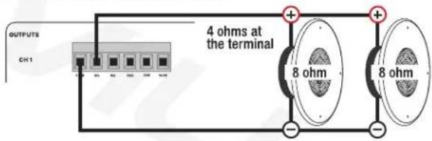
8-Ohm Connections
4-Ohm Speakers wired in SERIES

16-Ohm Speakers wired in PARALLEL
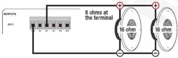
16-Ohm Connection
8-Ohm Speakers wired in SERIES

In-Wall Volume Controls
Although the ROCKMATRIX 4 offers individual zone volume controls, there may be occasions when you may want to adjust the volume of a specific zone without having to return to the amplifier. In-wall volume controls are the perfect solution and they are relatively easy to set up. Below is a general wiring guide to assist you in the installation of in-wall volume controls. As with any installation that requires running wires through your walls, be sure to check local code requirements.
A typical in-wall volume control consists of a face plate with a volume control knob on the front side and a step down transformer with in/out connections on the back side. Keep in mind that these volume controls come in a range of wattage ratings. The control you use must match the wattage of your speakers. You can use a higher rated control for lower wattage speakers, but you cannot use a lower rated control for higher wattage speakers.

Using high quality 16 AWG, 2 or 4 conductor, heavy gauge, CL2 or CL3 rated, 100% Oxygen-Free Copper (OFC) speaker wire, connect the desired zone output's +/- screw terminals to the IN+ and IN- terminals on the volume control. Next, connect the +/- speaker wires from your speakers to the SP- and SP+ terminals on the volume control. Make sure to observe proper polarity on all connections. Please note, this example shows connections for one zone. You can connect volume controls to any of the 4 zones.

Inputs/Outputs
![graph TD A["Amplifier"] --> B["Powered Sub"] C["Microphones"] --> D["Condenser Mics (use phantom power)"] E["Laptop"] --> F["Tape Deck"] G["CD Player"] --> H["MP3 Player"] I["CD Player"] --> J["Tape Deck"] K["Mixing Console"] --> L["DJ Controller"]](/content/2026/07/1482579/images/55a73455b1b1b2a72fc604a25c7533c10ca8d1245b7c653a046874a6a6e2689b.jpg)
Operation
Assigning Zones
Use the INPUT selector and OUTPUT selector buttons to route the input of any channel to any zone.
- Press the INPUT selector button to switch to the desired input channel. Press the button repeatedly to cycle through the input channels. Once you've found the desired input, the ON LED indicator of that input will light up.
- Now choose the output zone by pressing the output button for that zone. Multiple zones can be selected. Once you've selected your output zones(s), the OUTPUT LED indicators on the INPUT channel(s) will light up indicating which output zone(s) have been selected.
Please note, although you can assign any number of output zones to any input channel, but you can only set one input channel at a time.
Bluetooth Pairing
To connect your iPod, iPhone, MP3 player, Android phone, or any other Bluetooth-capable device, follow the steps listed below.
- Make sure the unit's power switch is in the ON position.
- Turn on the Bluetooth feature on your device and ensure that it is discoverable.
- Push the Mode button on the unit until you are in Bluetooth mode (LCD screen will display the word "Bluetooth").
- Look for "ROCKMATRIX 4" on the list of available devices and select it.
- Once connected, the LCD screen will display the word "Connected".
Please note, the unit will remember the last paired device. To force disconnect all paired devices, press and hold the REPEAT button for 5 seconds.
Bluetooth Playback
You can control playback from your device or from the MP3 control panel on the ROCKMATRIX 4:
- Press Play/Pause to begin or pause music playback.
- To skip songs, press the PREVIOUS/NEXTbuttons.
- Volume can be controlled from your device as well as the ROCKMATRIX 4. Please note, there are two volume controls on the amplifier which can affect Bluetooth playback: the PREVIOUS/NEXT buttons (see items 28 and 29 in the Functions section; default setting for these controls is max volume) and the CH4 volume control. These controls must be set separately as they work independently of each other.
USB/SD
- Inserting a USB flash drive or an SD card will set the ROCKMATRIX 4 to USB/SD mode and it will automatically begin to play music. Make sure the CH4 LINE/MP3 selector switch a the back of the unit is set to MP3.
Operation (continued)
- To skip songs, press the PREVIOUS/NEXT buttons. Press and hold these buttons to rewind or fast forward.
- To access files and folders within a USB drive or SD card, press the FOLDER button and use the PREVIOUS/NEXT buttons to navigate the files within the folder. The MP3 module supports MP3 and WAV files.
- Volume is controlled via the CH4 volume knob.
Features
• 440 Watts Total RMS @ less than 1% THD (110 Watts RMS per zone x 4 zones)
- 4 separate output zones allow you to route each input channel to multiple zones
• Supports multi zone installations using 70 volt, 100 volt, 16 ohm, 8 ohm, and 4 ohm speaker setups
- 4 line/mic inputs (2 of the mic inputs have selectable phantom power for condenser mics)
- 19" rack mountable (removable rack brackets)
• Built-in 1W monitor speaker allows you to listen to playback on any zone
• 100 volt RMS Power: 4 x 110 Watts RMS/70 volt RMS Power: 4 x 110 Watts RMS
- 4 ohm RMS power: 4 x 110 Watts RMS/8 ohm RMS power: 4 x 110 Watts RMS/16 ohm RMS power: 4 x 110 Watts RMS
• Built-in Bluetooth 5.0 chip allows audio streaming with matrix assigning to any zone(s)
- USB input to play audio stored on a thumb drive with matrix assigning to any zone(s) (32GB max)
- SD card slot to play music stored on an SD Card with matrix assigning to any zone(s) (32GB max)
- Separate volume control for MIC1/LINE1, MIC2/LINE2, MIC3/Line3, MIC4/LINE4/MP3 inputs
• Bass and treble controls
• Built in limiter and clipping indicator
- MIC 1 priority button will lower the music when talking into the mic when priority is activated
- 6 segment signal level LED indicators (-10dB, -6dB, -3dB, 0dB, limit, clip)
• Built-in fan cooling system keeps component cool at all times
- Built-in 1/4 " fire input will override the system when activated in case of emergencies
- Siren output allows you to connect a siren that would get activated in case of an emergency
Features (continued)
• Emergency DC 24V input terminals allow you to connect a 24V battery to power the amp in case of a power outage
• Weight: 25.1lbs
- Dimensions with the included rack mount ears attached: 19" x 14.2" x 3.54" inches
- Dimensions without rack mount ears: 17.3" x 14.2" x 3.54" inches
Troubleshooting
| PROBLEM | SOLUTION |
| No power | 1. Make sure the unit is plugged in and the power switch is in the ON position.2. Check that the power cable is properly plugged into the wall socket.3. Check and replace the fuse if necessary.4. If people or equipment tend to step and roll over or stretch your power cable it can get damaged. Check the power cable for damage. If the cable is damaged, discontinue using the unit until the cable can be repaired. |
| No sound/low sound/distorted sound | 1. Check that all appropriate cables and wires are plugged in correctly.2. Check the channel input and channel output volume and gain settings.3. Check the volume settings on your input devices.4. If using wall volume controls, be sure the volume is set properly.5. Make sure the proper input source is selected. Also, check your input/output zone settings (see page 14).6. Make sure your are using the proper type of speakers.7. Make sure speakers are wired correctly (plus to plus, minus to minus; not plus to minus or vice versa).8. Make sure the speakers are wired to the correct outputs (no 4 to 16-ohm speakers should be wired to the 70/100 outputs).9. Make sure speaker transformer taps are set properly.10. Make sure speakers' power ratings match the amplifier's.11. Make sure the CH4 LINE/MP3 button is set to the proper source. |
| Buzzing sound | Make sure you are using the proper cable. Check the requirements of the connected gear and the inputs on the amplifier and make sure you are using the appropriate cable. This unit's 1/4 " mic inputs are TRS (balanced) so you will need a TRS mic cable. For line inputs be sure to use high quality RCA cables. |
| Mic feedback or poor sound | 1. Point mics away from any nearby speakers.2. Make sure the microphones are on and the volume controls are properly set.3. Make sure the microphone cables are properly connected and that you are using good quality TRS mic-specific cables. |
| Bluetooth pairing fails | 1. Check to see that both devices are turned on and that your Bluetooth device is discoverable.2. Turn both devices off and then on again.3. Make sure you've selected the proper source.4. Make sure that the Bluetooth device is within 5 feet of the unit.5. Move both devices away from other Bluetooth devices.6. Make sure that the unit is not paired to a previously paired device. |
| No SD or USB playback | 1. Make sure you've selected the proper source.2. Make sure that the audio files are in the specified format:MP3, WAV.3. Make sure the USB drive's/SD card's capacity is not more than 32GB. |
FEDERAL COMMUNICATIONS COMMISSION COMPLIANCE INFORMATION
Responsible party name: Rockville
Address: 600 Bayview Ave.
Entrance A
Inwood, NY 11096
Hereby declares that the product(s) ROCKMATRIX 4 complies with FCC rules as mentioned in the following paragraph:
This device complies with Part 15 of the FCC rules. Operation is subject to the following two conditions: (1) this device may not cause harmful interference, and (2) this device must accept any interference received, including interference that may cause undesired operation.
Note: This equipment has been tested and found to comply with the limits for a Class B digital device, pursuant to Part 15 of the FCC rules. These limits are designed to provide reasonable protection against harmful interference in a residential installation. This equipment generates, uses, and can radiate radio frequency energy and, if not installed and used in accordance with the instructions, may cause harmful interference to radio communications. However, there is no guarantee that interference will not occur in a particular installation. If this equipment does cause harmful interference to radio or television reception, which can be determined by turning the equipment off and on, the user is encouraged to try to correct the interference by one or more of the following measures:
• Reorient or relocate the receiving antenna.
- Increase the separation between the equipment and receiver.
- Connect the equipment to an outlet on a circuit different from that to which the receiver is connected.
- Consult the dealer or an experienced radio/TV technician for help.
ROCKVILLE

RockvilleAudio.com
© 2026 ROCKVILLE // Features and specifications are subject to change and/or improvement without notice.
- ROCKVILLE
- ROCK MATRIX 4
- 4-ZONE 70V COMMERCIAL AMPLIFIER
- OWNER'S MANUAL
- ATTENTION: WATCH THIS VIDEO BEFORE FIRST USE
- INCLUDES
- IMPORTANT SAFETY INSTRUCTIONS
- TO REDUCE THE RISK OF ELECTRICAL SHOCK, NEVER OPEN THE UNIT. NO USER SERVICEABLE PARTS INSIDE. WE RECOMMEND SENDING THE UNIT TO THE ROCKVILLE SERVICE CENTER FOR ANY REPAIRS
- INTRODUCTION
- WHAT IS 70 VOLT
- FUNCTIONS
- INPUT CHANNELS
- OUTPUT CHANNELS
- FUNCTIONS (CONTINUED)
- INPUT/OUTPUT SELECTORS
- MONITOR
- MP3 MODULE
- REMOTE CONTROL
- SETUP
- SELECTING INPUT CABLES
- RACK MOUNTING
- CONNECTING SPEAKERS (CONTINUED)
- OUTPUT CONFIGURATIONS
- MULTI-ZONE 70V/100V SPEAKER OUTPUT
- MULTI-ZONE CONNECTION EXAMPLE
- OUTPUT CONFIGURATIONS (CONTINUED)
- 4-OHM CONNECTIONS
- 8-OHM CONNECTIONS
- 16-OHM CONNECTION
- IN-WALL VOLUME CONTROLS
- OPERATION
- ASSIGNING ZONES
- BLUETOOTH PAIRING
- BLUETOOTH PLAYBACK
- USB/SD
- OPERATION (CONTINUED)
- FEATURES
- FEATURES (CONTINUED)
- FEDERAL COMMUNICATIONS COMMISSION COMPLIANCE INFORMATION
- ROCKVILLEAUDIO.COM
Marque : Rockville
Modèle : Rock Matrix 4
Catégorie : Recepteur