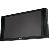
InformaCast VIP-LD221C-IC - Système d'alerte audio-visuel Valcom - Notice d'utilisation et mode d'emploi gratuit
Retrouvez gratuitement la notice de l'appareil InformaCast VIP-LD221C-IC Valcom au format PDF.


| Type de produit | Haut-parleur IP de table ou mural |
| Marque | Valcom |
| Modèle | InformaCast VIP-LD221C-IC |
| Dimensions (L x H x P) | 20 x 15 x 10 cm |
| Poids | 1.0 kg |
| Alimentation | PoE (Power over Ethernet) IEEE 802.3af |
| Puissance audio | 20 W |
| Connectivité | Ethernet RJ45 |
| Protocole | SIP, InformaCast |
| Fonctions principales | Diffusion de messages en direct ou préenregistrés, paging, alertes d'urgence, compatibilité avec le système InformaCast |
| Entretien | Nettoyer avec un chiffon doux et sec |
| Sécurité | Installation par un professionnel qualifié, respect des normes électriques locales |
| Indice de protection | IP20 (intérieur) |
| Garantie | 1 an |
FOIRE AUX QUESTIONS - InformaCast VIP-LD221C-IC Valcom
Questions des utilisateurs sur InformaCast VIP-LD221C-IC Valcom
0 question sur cet appareil. Repondez a celles que vous connaissez ou posez la votre.
Poser une nouvelle question sur cet appareil
Téléchargez la notice de votre Système d'alerte audio-visuel au format PDF gratuitement ! Retrouvez votre notice InformaCast VIP-LD221C-IC - Valcom et reprennez votre appareil électronique en main. Sur cette page sont publiés tous les documents nécessaires à l'utilisation de votre appareil InformaCast VIP-LD221C-IC de la marque Valcom.
MODE D'EMPLOI InformaCast VIP-LD221C-IC Valcom
VIP-LD222-IC
InformaCast® Compliant Dual LCD Display Speaker with Flashers
VIP-LD221C-IC
InformaCast® Compliant Single LCD Display Speaker with Flashers
INTRODUCTION
The VIP-LD222-IC InformaCast® Compliant Dual LCD Display Speaker with Flashers and the VIP-LD221C-IC InformaCast® Compliant Single LCD Display Speaker with Flashers combine audio paging and intercom with visual notifications. Bright flashers on the bottom edge attract attention for important announcements. Templates provide preset display areas for easy and quick visual layout.
SPECIFICATIONS
Features
- Cost effective and versatile solutions for applications requiring audio and visual alerts
- Multiple template options for displaying clocks, images and messages
- Synchronized flashing when used with additional Valcom Flashers
• Wall or Ceiling mountable
• VIP-LD222-IC has displays on both sides
• VIP-LD221C-IC has the display on one side only
Video Specifications
- 178° Vertical x 178° Horizontal viewing angle
• Contrast Ratio 1000:1 - White luminance 500 cd / m2
• Full HD Resolution (1920 x 1080) - 60 Hz Refresh Rate
• High brightness Flashers, Red, Green, Blue, White LEDs, combine to create millions of colors
Audio Specifications
• Full duplex talkback audio with omni-directional microphone
• Dual speakers with 5 Watt output
Activation Methods
- Singlewire InformaCast server
• Valcom Site Manager server
• Valcom Interactive Console - Valcom Group Page
- SIP Phone Call

Nominal Power Requirements
• VIP-LD222-IC Dual Display
IEEE 802.3bt Type 4, 90 Watts minimum
- VIP-LD221C-IC Single Display
IEEE 802.3bt Type 3 or 4, 60 Watts minimum
Input/Output
- Two Contact Closure Inputs
• One Relay Output, Form C, Rated 1A @ 24 Vdc
• One Line Level Audio Output
• One Line Level Audio Input for local audio
Dimensions / Weight
- 12.75" H x 23.75" W x 3.0" D (32.4cm H x 60.3cm W x 7.6cm D) Ceiling mount Height with bracket 14.0" (35.6cm) Wall mount Width with bracket 25.0" (63.5cm)
• VIP-LD222-IC 15.1 lbs. (6.9 kg)
• VIP-LD221C-IC 12.5 lbs. (5.7 kg)
Environment
• Temperature: +32 to +104°F (0 to +40°C)
• Humidity: 0 to 85% non-precipitating
INSTALLATION
Operation
The VIP-LD221C-IC or VIP-LD222-IC provide visual notification, audible notification, or both simultaneously. Messages are created by the Singlewire InformaCast server and delivered over the network. The bright LED flashers on the bottom of the display may be activated by priority or group membership. Live voice paging can be initiated via SIP registration to a Voice over IP (VoIP) telephone system, or from a Valcom voice gateway device. When idle, the display can provide time and date using the built-in customizable clock display templates.
Mounting
NOTE: The LED flashers can synchronize with other Valcom IP Flashers, but not with other manufacturers' devices. Therefore, it must not be installed where the flash from other, non-Valcom flashers may be seen.
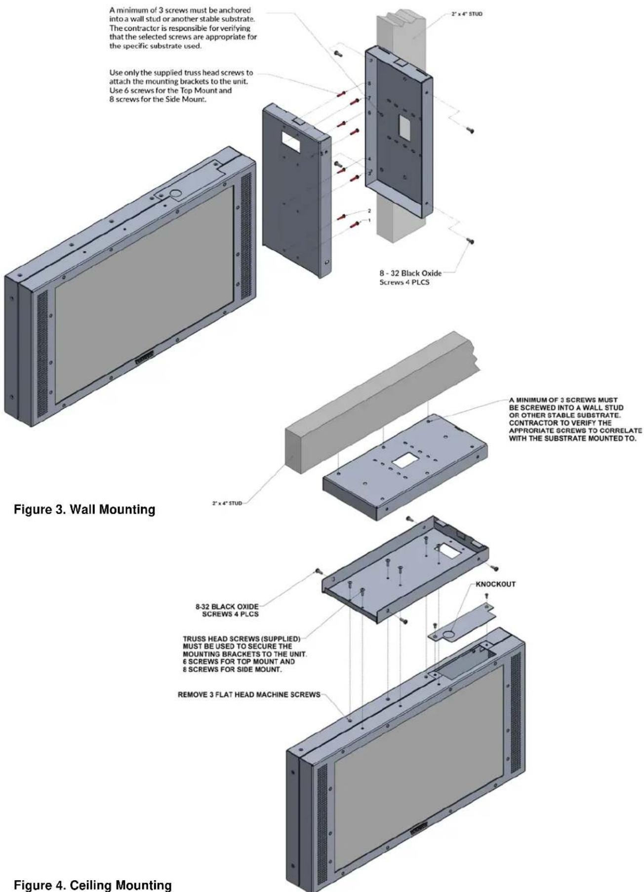
The Displays are designed for wall or ceiling mounting. The two-piece mounting bracket included with the Display will work for either arrangement. The bracket with the larger hole in the center will attach to the wall or ceiling. The bracket with the smaller hole near one end will be attached to the Display. The bracket will properly fit on the Display in only one direction.
For wall mounting, remove the side wiring access cover and 4 existing screws in the Display case. Use 8 truss head screws (provided) to attach the bracket to the side of the Display. The top access panel may also be temporarily removed to access the wiring connections.
For ceiling mounting, remove the top access cover and 3 existing screws in the Display case. Use 6 truss head screws (provided) to attach the bracket to the top of the Display.
The second piece of the mounting bracket must be properly attached to the wall or ceiling, oriented so that the slots at one end of the bracket will line up with the tabs on the bracket attached to the Display. Use fasteners appropriate for the wall construction to securely mount the bracket.
Route the ethernet cable and relay or contact closure wires (if used) through the hole in the wall or ceiling mounted bracket, then through the hole in the Display mounting bracket and make connections to the appropriate terminals on the Display.
Slide the Display mounting bracket over the wall or ceiling bracket and align the tabs on the Display bracket with the slots in the wall/ceiling bracket. Use four #8-32 black oxide screws to securely join the two brackets.
Network / Power Connections
The VIP-LD222-IC or VIP-LD221C-IC has one RJ-45 Network connector with two LEDs to indicate link speed and activity.
- Green LED indicates Link Speed: Off: 10 Mbit speed On steady: 100 Mbit speed Flashing: 1000 Mbit speed
- Yellow LED indicates activity: On steady: Connected Flashing: network activity
The only method of powering the VIP-LD222-IC Dual Display is via a Power over Ethernet (PoE) switch or power injector meeting the 802.3bt Type 4 specification, supplying a minimum of 90 Watts.
The only method of powering the VIP-LD221C-IC Single Display is via a Power over Ethernet (PoE) switch or power injector meeting the 802.3bt Type 3 or 4 specification, supplying a minimum of 60 Watts.
Make all required signal connections before connecting to an Ethernet switch or power injector meeting the specification.
Input / Output Connections
Line In
Audio connected to the Line In terminals will be routed to the built-in speakers. This audio will be muted when a Page or Intercom Call is active.
Line Out
Audio received by the Displays will be output on the Line Out terminals. This is typically used to provide line level audio to self-amplified speakers or amplifiers.
SW1, GND, SW2
Terminals labeled SW1, SW2 and GND (ground) provide two inputs typically used for Call Switches to initiate intercom calls. Input 1 uses terminals SW1 and GND; input 2 uses SW2 and GND.
Relay
A Form C Relay is available using the NO (Normally Open), COM (Common) and NC (Normally Closed) terminals.
Reset
A Reset button is located behind a pin hole in the top of the Display and may be used to return the Display to factory default settings. Use a small diameter object, such as a toothpick, to access the button. Press the Reset button for more than 10 seconds, but less than 20, to reset the IP address and other configuration to factory default.
Pressing the Reset button for more than 20 seconds will reset all configuration, including the password. See Figure 2 for Reset button location.
Setup
The VIP-LD222-IC or VIP-LD221C-IC will attempt to acquire an IP address using DHCP and register to the InformaCast server. Information specific to your application will need to be programmed into the InformaCast server. Additional setup will be done using the VIP-102B IP Solutions Setup Tool. Download the latest version of the free IP Solutions Setup Tool from the Valcom web site at www.valcom.com/vipsetuptool
Technical Assistance
Assistance in troubleshooting is available from the factory. Call (540) 563-2000 and press 1 for Technical Support or via email at support@valcom.com. When requesting assistance, you should include all available information. General information and troubleshooting procedures are available on the Valcom website at www.valcom.com. Valcom equipment is not field repairable. Valcom, Inc. maintains service facilities in Roanoke, VA.
Should repairs be necessary, attach a tag to the unit clearly stating your company name, address, phone number, contact person and the nature of the problem. Send the unit to:
Valcom, Inc.
Repair & Return Dept.
5614 Hollins Road
Roanoke, Va. 24019-5056
WARRANTY
Warranty information may be found on our website at www.valcom.com/warranty

Figure 1. Wiring Access

Figure 2. Top Access Panel, Wiring Connections
- VIP-LD222-IC
- INFORMACAST® COMPLIANT DUAL LCD DISPLAY SPEAKER WITH FLASHERS
- VIP-LD221C-IC
- INFORMACAST® COMPLIANT SINGLE LCD DISPLAY SPEAKER WITH FLASHERS
- INTRODUCTION
- SPECIFICATIONS
- FEATURES
- VIDEO SPECIFICATIONS
- AUDIO SPECIFICATIONS
- ACTIVATION METHODS
- NOMINAL POWER REQUIREMENTS
- INPUT/OUTPUT
- DIMENSIONS / WEIGHT
- ENVIRONMENT
- INSTALLATION
- OPERATION
- MOUNTING
- NETWORK / POWER CONNECTIONS
- INPUT / OUTPUT CONNECTIONS
- LINE IN
- LINE OUT
- SW1, GND, SW2
- RELAY
- RESET
- SETUP
- TECHNICAL ASSISTANCE
- WARRANTY
Marque : Valcom
Modèle : InformaCast VIP-LD221C-IC
Catégorie : Système d'alerte audio-visuel