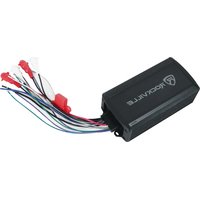
PS40 - Recepteur Rockville - Notice d'utilisation et mode d'emploi gratuit
Retrouvez gratuitement la notice de l'appareil PS40 Rockville au format PDF.


| Type de produit | Récepteur audio |
| Marque | Rockville |
| Modèle | PS40 |
| Dimensions (L x P x H) | 430 x 250 x 80 mm |
| Poids | 3,5 kg |
| Alimentation | Secteur 220-240 V, 50 Hz |
| Consommation électrique | 30 W |
| Fonctions principales | Réception AM/FM, lecture USB, entrée auxiliaire, sortie casque |
| Puissance de sortie | 2 x 20 W RMS |
| Entrées audio | 1 x RCA, 1 x AUX 3,5 mm, 1 x USB |
| Sorties audio | 1 x casque 3,5 mm, bornes haut-parleurs |
| Réglages | Volume, graves, aigus, balance |
| Affichage | Écran LCD rétroéclairé |
| Connectivité | Bluetooth 5.0 (portée 10 m) |
| Entretien et nettoyage | Essuyer avec un chiffon doux et sec. Ne pas utiliser de produits abrasifs. |
| Sécurité | Ne pas exposer à l'humidité ni aux sources de chaleur. Débrancher avant nettoyage. |
| Pièces détachées et réparabilité | Pièces disponibles sur demande auprès du service après-vente |
| Informations générales | Notice d'utilisation disponible en téléchargement sur le site du fabricant |
FOIRE AUX QUESTIONS - PS40 Rockville
Questions des utilisateurs sur PS40 Rockville
0 question sur cet appareil. Repondez a celles que vous connaissez ou posez la votre.
Poser une nouvelle question sur cet appareil
Téléchargez la notice de votre Recepteur au format PDF gratuitement ! Retrouvez votre notice PS40 - Rockville et reprennez votre appareil électronique en main. Sur cette page sont publiés tous les documents nécessaires à l'utilisation de votre appareil PS40 de la marque Rockville.
MODE D'EMPLOI PS40 Rockville
ROCKVILLE
PS40
4-CHANNEL IP65 ATV/UTV/MOTORCYCLE MICRO AMP w/WIRELESS STREAMING
OWNER'S MANUAL
ATTENTION: WATCH THIS VIDEO BEFORE FIRST USE!
Scan the QR code or go to rockvillesupport.com/ps40 for essential information, guides (video and/or written), and tips to make the most out of your purchase.
If you prefer written instructions, please read ahead!
With Rockville you get many options.

Missing items? If you ordered a bundle that includes more than one product and you are missing part of your bundle then it just means your order shipped from two different warehouses. You will receive the remaining items very soon. If you have any concerns or inquiries, feel free to call our customer support center at 1-646-758-0144, 24 hours a day/7 days a week.
POCTIVIL
Thank you for purchasing this Rockville PS40 amplifier. Please read this owner's manual carefully for proper use. Should you need assistance, please call our technical help line at 1-646-758-0144, 24 hours a day/7 days a week.
IMPORTANT SAFETY INSTRUCTIONS

- To reduce risk of electric shock, never open the unit. There are no user serviceable parts, refer service to the Rockville service center.
- Please ensure that the unit is situated in a properly ventilated area.
Wiring

- Rear Left (white) and Rear Right (red) inputs (Ch3-4)
- Front Left (white) and Front Right (red) inputs (Ch1-2)
- Remote turn-on cable (blue)
- Ground cable (black)
- Power cable with in-line fuse (+12V, red)
- Front Left negative (white w/black stripe) and Front Left positive (white) speaker output cables (Ch1)
- Front Right negative (grey w/black stripe) and Front Right positive (grey) speaker output cables (Ch2)
- Rear Left negative (green w/black stripe) and Rear Left positive (green) speaker output cables (Ch3)
- Rear Right negative (purple w/black stripe) and Rear Right positive (purple) speaker output cables (Ch4)
Power Connections
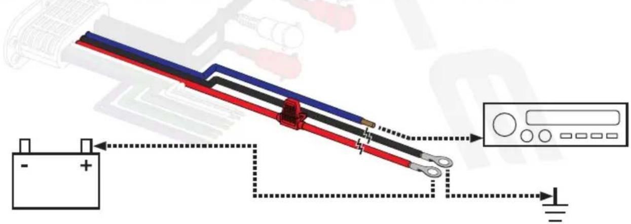
- Make sure to disconnect the NEGATIVE (-) terminal from your vehicle's battery.
- Attach a 10-gauge or heavier wire to the black cable from the harness marked GND. The connection should be as close to the amp as possible. The wire should terminate in a ring connector. Connect the ring connector to a metal part of the vehicle's chassis, making sure that there is no paint or other insulator blocking a good ground connection. If needed, you can connect to the battery's negative terminal.
- Attach a 10-gauge or heavier wire to the red cable from the harness marked +12V to the battery's POSITIVE (+) terminal. The power wire should terminate in a ring terminal connected directly to the POSITIVE (+) terminal.
- Connect the blue remote wire to the head unit's remote output using 18-gauge or heavier wire. This connection is responsible for turning the amplifier on and off with the rest of the system. Should your head unit not have any turn-on leads, you can wire the remote terminal to an accessory lead, which turns the amplifier on with your vehicle's ignition.
Please note, it is a good practice to feel the power and ground wires near the amplifier after using the amp for a while. If the wires feel hot to the touch, you probably have a bad or loose connection. If after adjusting your connections the wires still feel hot, you should upgrade to the next heaviest-gauge wire. As connections can work loose due to vehicle vibrations, we recommend periodically tightening all power and ground connections.
Input Configurations
4-Channel Input
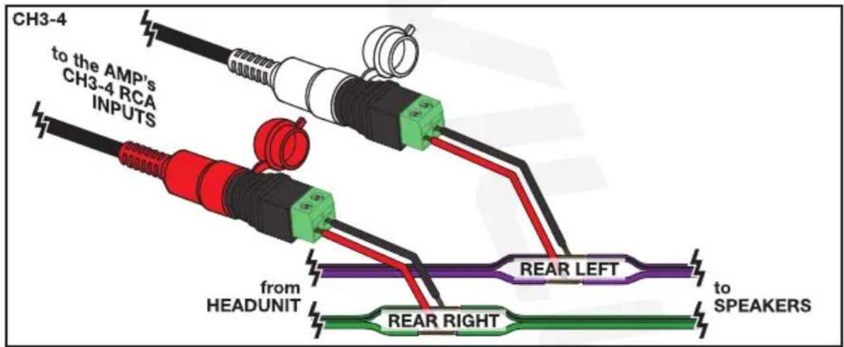
Connect your head unit's RCA outputs to the amplifier's Front (Channel 1-2) and Rear (Channel 3-4) Left/Right RCA input jacks. Make sure to run the RCA cables SEPARATE from your power, remote, and ground cables. This will avoid unwanted noise and interference.

High Level Inputs
Many factory radios do not have preamp outputs; thus, the PS40 has High Level input capability. Also referred to as Speaker Level inputs, High Level inputs allow you to connect to the factory speaker wires. They are called High Level inputs because they convert the high voltage running through factory speaker wires to one the amplifier can handle. These inputs will provide the end user with clean, well-defined sound for optimal musical enjoyment. PLEASE NOTE: The High Level inputs also feature Auto-Start Smart Turn-On. This function senses when there is a signal from the head unit and automatically turns on the amplifier; hence, no need to run a Remote Turn-On wire.

Output Configurations
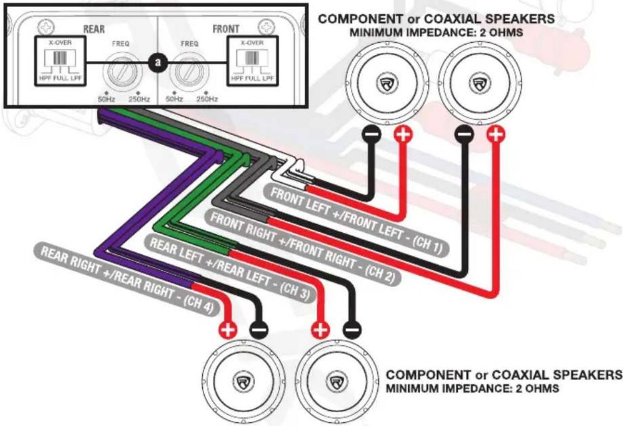
Install any combination of component or coaxial speakers independently on channels 1 – 4, being careful not to load any single channel below 2-ohm. For typical 6" x 9" or 6.5" or component or coaxial speaker installs, set the X-OVER mode switches to full range (FULL) (a) or HPF depending on your setup and what speakers you are using.
4-Channel Amp in 2-Channel Bridged Mode
Channels 1-2 and Channels 3-4 should be bridged as per the diagram. Wire one woofer to Channel 1's positive (+) terminal and Channel 2's negative (−) terminal. Wire one woofer to Channel 3's positive (+) terminal and Channel 4's negative (−) terminal. Set the crossover switches to LPF (a) if using subwoofers.
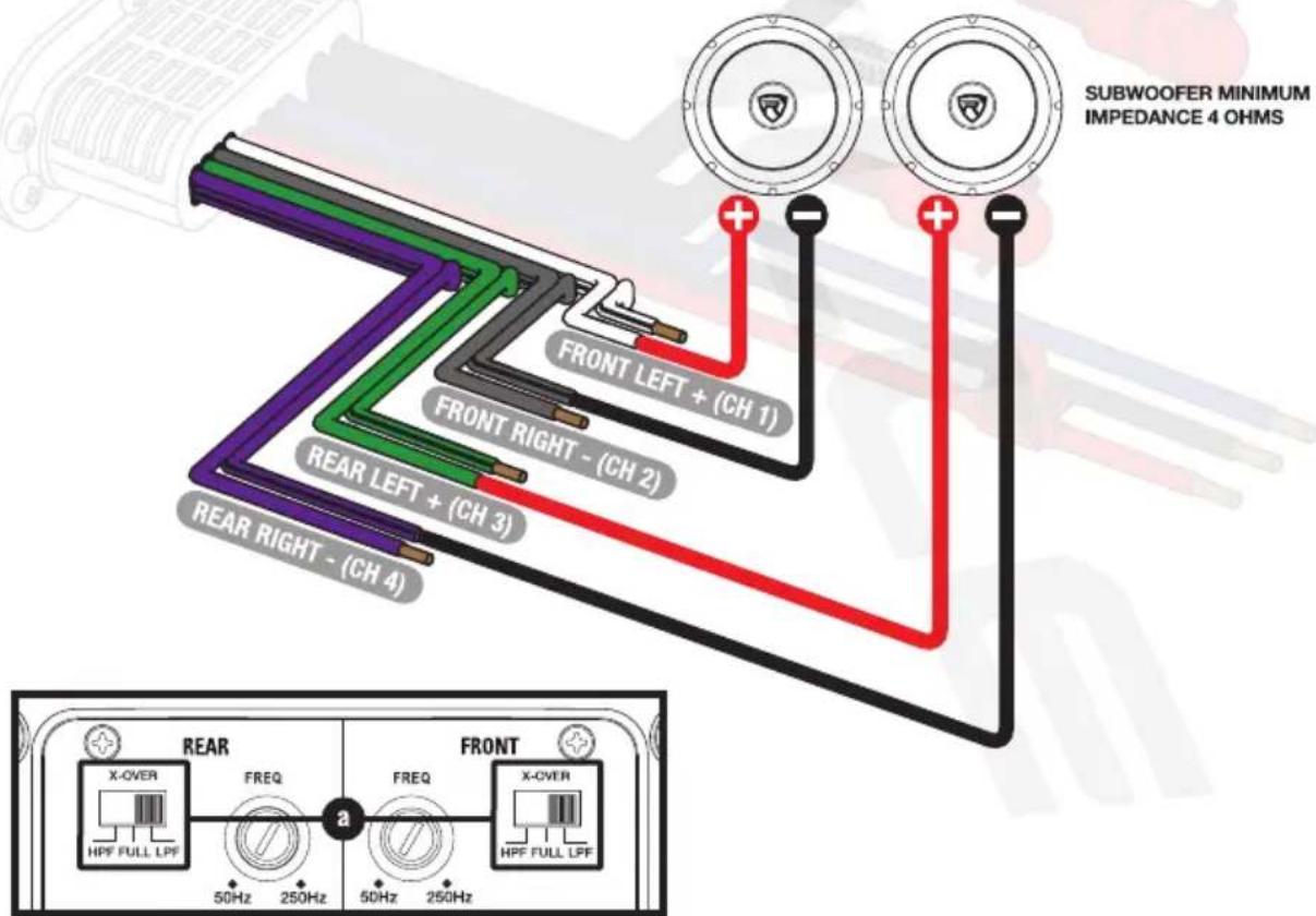
Output Configurations (continued)
4-Channel Amp in 3-Channel Mode
Channels 1 and 2 should be wired to component or coaxial speakers with no lower than 2-ohm load per channel in stereo. Channels 3 and 4 should be bridged as per the diagram, wiring the woofer to Channel 3's positive (+) wire and Channel 4's negative (−) wire. Set the Channel 3-4 Crossover Mode Switch for the front (Channels 1-2) to FULL range (a) and switch for the rear (Channels 3-4) to LPF (b).
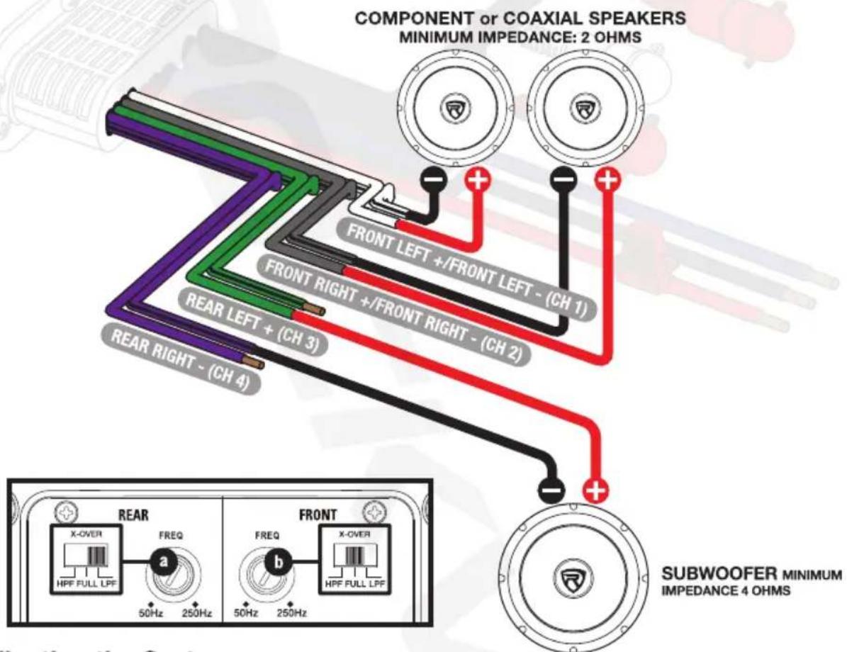
Adjusting the System
- Once the system is setup, set all crossover points to the approximate settings. In the case of a basic full range system, set the Full Range (FULL) or High Pass (HPF) crossover at 100Hz or so. Turn the controls using a small flathead screwdriver. Do not apply any pressure while turning as this might break the control unit. In the case of a basic subwoofer system, set the Low Pass (LPF) crossover at 100Hz or so. As mentioned before, turn the controls using a small flathead screwdriver, being careful to not apply too much pressure.
- Set the amplifier's Input Sensitivity using the control accessible on the side of the amplifier marked LEVEL (gain). Turn it counterclockwise to the MIN position. Adjust your head unit's volume gain to the maximum it can go before signal distorts or to the loudest gain, which is usually about 75% – 85% on most head units (you can also use an oscilloscope to see at what gain level your head unit distorts). When you begin to hear distortion, back down one notch. Now turn the LEVEL control on the amp clockwise until you hear distortion, then turn it counterclockwise by a notch or until the distortion is gone. The amp's input sensitivity is now set. It is helpful to have a second person to help you set the gain. When setting up a multi-amp system, set each amplifier's level controls separately. Start off with the bass amplifier, then adjust the highs amplifier's level control to match. Please note that the level control of any vehicle's amplifier should not be mistaken for a volume control. It is a sophisticated device designed to match the output level of your source unit to the input level of the amplifier. Do not adjust the amplifier level to maximum unless your input level requires it. Your system can also be extremely sensitive to noise when the input level is set to maximum and does not match your input signal. These adjustments need to be made only once when first setting up the system.
- Once you are satisfied with the level control settings, use any equalizer controls to adjust the system's tonal level for personal preference. Keep in mind that after equalizing you may have to go back and reset the amplifier's level controls. If your unit has been professionally installed please do not change the gain settings set by the installer, he or she is the professional!
Features
Wireless Streaming
When the unit powers up, the wireless streaming LED indicator (located on the left side of harness) will begin to flash indicating that it is in pairing mode. Look for and select PS40 from your device's list of available wireless streaming devices. If pairing is
Features (continued)
successful, the LED indicator will remain solid blue. Please note, a wireless streaming connection will override RCA input. If you wish to return to RCA input, you will need to end the connection via your device.
Bass EQ
The bass EQ allows you to add 3dB or 6dB of bass boost. Utilize the equalizer to tailor bass response to your system's needs. Make sure your speakers can handle the extra power output.
Frequency Control
The frequency knob allows you to set the frequency range of the selected X-OVER setting. For example, if your X-OVER is set to LPF, you can set the knob to 150Hz, which will keep your speakers from playing any frequencies below 150Hz.
Status LED
This model features one LED (located on the right side of the harness) that provides indication of the amplifier's status. The LED will light green when the amplifier is receiving proper power, ground, and remote voltages. In case the amplifier encounters a diagnostic condition as listed below, the LED will light red indicating a diagnostic condition. When a diagnostic condition is sensed, the amplifier will then turn into self-preservation mode and if the cause of the diagnostic condition is not corrected will eventually shut down.
Thermal Protection: When the amplifier reaches an unsafe operating temperature of 80 degrees Celsius, the amplifier will turn off. Once the amplifier cools down to a safe temperature, it will automatically turn on again. If you live in a hot climate, we suggest installing additional cooling fans to exhaust the hot air which can build in an enclosed space. This will help keep the ambient temperature as low as possible so that your amps work flawlessly and without any musical interruption.
Speaker Short Circuit Protection: Should your speakers short circuit due to voice coil burn out, or should the amplifier sense an impedance too low to handle, the protection LED will light red, indicating a diagnostic condition. Turn off your system, disconnect one speaker at a time, and try to determine which speaker might be faulty. Correct the condition and restart the amplifier. You must reset the amplifier by turning it OFF and then ON again by the Remote power connection after correcting a diagnostic condition. (Turn your radio off and then on again.)
Input Overload Protection: This circuit will either shut down the amplifier completely or make the amplifier spurt on and off indicating that it is in a diagnostic condition. Turn the system off and reduce the gain on the amplifier or volume from your head unit. This should result in a corrected condition.
DC Offset Protection: Should any DC voltage try to enter the amplifier via the speaker terminals it will cause the amplifier to shut down and not operate until this condition is remedied. This circuit will also protect damaging high DC voltages from reaching your speakers should your amplifier ever malfunction.
PLEASE NOTE: You must reset the amplifier by turning it OFF and then ON again after correcting a diagnostic condition (turn your radio off and then on again). If the amplifier stays in protection after a reset, it is most likely faulty.
Additional Features
• Built-in Wireless Streaming with Auto Pairing (You can run this amp without any receiver)
• IP65 waterproof rating
• Waterproof silicone covers on all inputs and control panel
- Conformal coated circuit board
- Anti-rust materials
- Micro Size amplifier can easily fit in tight spaces making it perfect for Motorcycles, UTV, ATV, etc
• Digital Class D Audio Topology
- Independent Crossover Controls for Front R/L (CH1-2) and Rear L/R (CH3-4)
• Full Range/Low Pass/High Pass Crossover
• RCA Low level inputs and High Level Inputs (with Auto ON)
• Waterproof RCA Input
• High-Speed MOSFET Power supply
• Status mode LED Indicator
• Wireless Streaming mode LED indicator
Specifications
- Dyno Certified RMS Power Ratings (Certified Dyno Test / Less than 1 % THD) (Use these ratings when comparing with top premium brands)
2 Ohms: 340 Watts (4 x 85 Watts)
4 Ohms: 200 Watts (4 x 50 Watts)
4 Ohm Bridged: 340w (2 x 170 Watts)
- Peak (Use these ratings when comparing with the top budget brands such as Boss, Power Acoustik, etc): Peak 2 Ohms: 1350 Watts
• Variable LPF/HPF Crossover: 50Hz – 250Hz
- Peak (Use these ratings when comparing with the top budget brands such as Boss, Power Acoustik, etc): Peak 2 Ohms: 1350 Watts - Variable LPF/HPF Crossover: 50Hz – 250Hz
Specifications (continued)
- Selectable 0/3/6dB Bass Equalizer
• Frequency Response: 20Hz – 20kHz
• Signal to Noise Ratio: (1 Watt into 4 Ohms) ≥75dB
• Input Sensitivity: 0.5V-15V
• Distortion (THD): ≤0.5%
• Stereo Separation: ≥45dB - Fuse Rating: 30A
• Dimensions (Inches): 7.56 L x 3.66 W x 2.07 H
Troubleshooting
| PROBLEM | SOLUTION |
| Unit will not power up | 1. Check your ground connection.2. Check that the Remote Input Turn-On has at least 5V DC.3. Check that there is battery power going to the +12V terminal.4. Check all fuses, replace if necessary.5. Make sure the Status LED is not red. If it is, shut off the amplifier briefly and then turn it back on. |
| Status LED is red when amplifier is powered up | 1. Turn down the volume control on the head unit to prevent overdriving.2. Check that there is good air flow around the amp.3. Check the STATUS LED section on page 8 for more information.4. Check speaker wiring polarity.5. Check power, ground, and remote wiring.6. Check voltages. |
| No Output | 1. Check the fuse.2. Check that the unit is properly grounded.3. Check that the Remote Input Turn-On has at least 5V DC.4. Check that all inputs to the unit are properly connected.5. Check speaker wiring and that you've observed proper polarity.6. Check the input source's power and output settings.7. There is a setting on your receiver that can disable your RCA outputs. The setting is under fader/balance control. On your receiver navigate to fader/balance and find the setting, then make sure you enable front, rear, and sub pre-amp outputs. Sometimes the head unit will allow you only to enable front and rear, which would cause the amp to have no sound. |
| Wireless Streaming | 1. Make sure that your Bluetooth device is discoverable.2. Make sure you've selected the proper source.3. Make sure that the wireless streaming device is within 5 feet of the unit.4. Make sure that the unit is not paired to another device. |
| Low Output | 1. Check that all inputs to the unit are properly connected.2. Check the input source's power settings.3. Check the head unit's/radio's settings.4. Check gains on the amp and X-OVER. |
| High Hiss in the sound | 1. Check that all inputs to the unit are properly connected.2. It is best to set the amplifier's gain control as low as possible while still maintaining enough headroom to power your speakers. The best subjective signal-to-noise ratio is achieved in this manner. Try to set the head unit's volume level as high as possible without distortion. |
| Squealing noise is present | Check for improperly grounded RCA interconnects. Keep the audio and power cables separated. |
| Distorted sound | Check that the Level control is set to match the signal level of the head unit and bring it back down. |
| Engine noise: Static type | 1. Route your input cables away from the vehicle's wiring.2. Use high quality RCA cables. |
| Engine noise: Alternator whine | 1. Check that the RCA grounds are not shorted to the vehicle chassis.2. Check that the head unit is properly grounded. |
FEDERAL COMMUNICATIONS COMMISSION COMPLIANCE INFORMATION
Responsible party name: Rockville
Address: 600 Bayview Ave.
Entrance A
Inwood, NY 11096
Hereby declares that the product(s) PS40 complies with FCC rules as mentioned in the following paragraph:
This device complies with Part 15 of the FCC rules. Operation is subject to the following two conditions: (1) this device may not cause harmful interference, and (2) this device must accept any interference received, including interference that may cause undesired operation.
Note: This equipment has been tested and found to comply with the limits for a Class B digital device, pursuant to Part 15 of the FCC rules. These limits are designed to provide reasonable protection against harmful interference in a residential installation. This equipment generates, uses, and can radiate radio frequency energy and, if not installed and used in accordance with the instructions, may cause harmful interference to radio communications. However, there is no guarantee that interference will not occur in a particular installation. If this equipment does cause harmful interference to radio or television reception, which can be determined by turning the equipment off and on, the user is encouraged to try to correct the interference by one or more of the following measures:
• Reorient or relocate the receiving antenna.
- Increase the separation between the equipment and receiver.
- Connect the equipment to an outlet on a circuit different from that to which the receiver is connected.
- Consult the dealer or an experienced radio/TV technician for help.
ROCKVILLE

- ROCKVILLE
- PS40
- OWNER'S MANUAL
- ATTENTION: WATCH THIS VIDEO BEFORE FIRST USE
- IMPORTANT SAFETY INSTRUCTIONS
- WIRING
- POWER CONNECTIONS
- INPUT CONFIGURATIONS
- 4-CHANNEL INPUT
- OUTPUT CONFIGURATIONS
- 4-CHANNEL AMP IN 2-CHANNEL BRIDGED MODE
- OUTPUT CONFIGURATIONS (CONTINUED)
- 4-CHANNEL AMP IN 3-CHANNEL MODE
- ADJUSTING THE SYSTEM
- FEATURES
- WIRELESS STREAMING
- FEATURES (CONTINUED)
- BASS EQ
- FREQUENCY CONTROL
- STATUS LED
- ADDITIONAL FEATURES
- SPECIFICATIONS
- SPECIFICATIONS (CONTINUED)
- FEDERAL COMMUNICATIONS COMMISSION COMPLIANCE INFORMATION
Marque : Rockville
Modèle : PS40
Catégorie : Recepteur