VIP-VAF-IC - Dispositif de signalisation lumineuse Valcom - Notice d'utilisation et mode d'emploi gratuit
Retrouvez gratuitement la notice de l'appareil VIP-VAF-IC Valcom au format PDF.


| Type de produit | Interphone/amplificateur de son |
| Marque | Valcom |
| Modèle | VIP-VAF-IC |
| Dimensions (L x H x P) | Environ 120 x 80 x 50 mm |
| Poids | Environ 300 g |
| Alimentation électrique | 24 V DC (via adaptateur secteur) |
| Consommation électrique | 5 W maximum |
| Puissance audio | 2 W RMS |
| Type de communication | Duplex intégral |
| Entrées audio | 1 entrée microphone (bornier) |
| Sorties audio | 1 sortie haut-parleur (bornier, 8 ohms) |
| Fonction d'appel | Bouton d'appel intégré avec sonnerie |
| Matériau du boîtier | ABS résistant aux chocs |
| Montage | Mural (vis incluses) |
| Température de fonctionnement | -10 °C à +50 °C |
| Entretien et nettoyage | Nettoyer avec un chiffon doux et sec. Ne pas utiliser de produits abrasifs. |
| Indice de protection | IP20 (usage intérieur uniquement) |
| Sécurité | Ne pas exposer à l'humidité ou à des températures extrêmes. |
| Pièces détachées | Adaptateur secteur (modèle VIP-PS-24V), câbles de liaison disponibles |
| Réparabilité | Produit non réparable par l'utilisateur. Contacter le SAV Valcom. |
| Garantie | 2 ans (pièces et main-d'œuvre) |
FOIRE AUX QUESTIONS - VIP-VAF-IC Valcom
Questions des utilisateurs sur VIP-VAF-IC Valcom
0 question sur cet appareil. Repondez a celles que vous connaissez ou posez la votre.
Poser une nouvelle question sur cet appareil
Téléchargez la notice de votre Dispositif de signalisation lumineuse au format PDF gratuitement ! Retrouvez votre notice VIP-VAF-IC - Valcom et reprennez votre appareil électronique en main. Sur cette page sont publiés tous les documents nécessaires à l'utilisation de votre appareil VIP-VAF-IC de la marque Valcom.
MODE D'EMPLOI VIP-VAF-IC Valcom
VIP-VAF-IC InformaCast® Compliant Multi-Color Flasher
INTRODUCTION
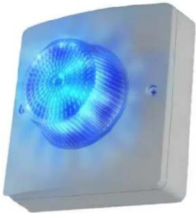
The VIP-VAF-IC InformaCast® Compliant Multi-Color Flasher is a private mode notification appliance that provides bright flasher functionality with both power and activation provided by the IP network. Multiple flashers may be synchronized to flash in unison.
SPECIFICATIONS
Features
- Cost effective and versatile solution to applications requiring visual alerts or flashers
• Power over Ethernet Plus (PoE+) 802.3at Class 4 compatible - 7 flash patterns and 10 brightness levels
• 16 High brightness, Red, Green, Blue, White LEDs, with up to 300 lumens each - 360° × 180° Coverage
- Night Ring functionality in conjunction with other Valcom IP speakers
- Synchronized flashing when used with additional Valcom Flashers
Activation Methods
- Singlewire InformaCast® server
• Valcom Site Manager server
• Valcom Interactive Console - Valcom Group Page
- SIP Phone Call
Input/Output
• One Normally Open Supervised Input
• One Normally Open Relay Output, Form A, Rated 1A @ 24 Vdc
Dimensions / Weight
- 5.76"H x 5.76"W x 3.10"D (14.6cm H x 14.6cm W x 7.9cm D)
• 1.2 lbs. (0.54 kg)
Nominal Power Requirements
• Via 802.3at PoE+ Class 4, 20W max
Environment
• Temperature: -40 to +123°F (-40 to +50°C)
• Humidity: 0 to 85% non-precipitating
• Ingress Protection: IP66 rated
Suitable for indoor or outdoor installation when properly installed.
INSTALLATION
Operation
The VIP-VAF-IC provides private mode notification via network connection. Activation of the Flasher is triggered by including the VIP-VAF-IC as a member of an InformaCast Paging group. The VIP-VAF-IC can also operate as a visual Night Ring device in conjunction with a SIP PBX and can provide audio Night Ring to other Valcom IP speakers when activated. Interface to customer telephone system can be via SIP registration to a Voice over IP (VoIP) telephone system, or FXO port (when used with a Valcom Enhanced Station Port).
Mounting
The VIP-VAF-IC is designed for single-gang, double-gang or octagon electrical box mounting or mounting directly to a solid surface.
NOTE: The VIP-VAF-IC can synchronize with other Valcom IP Flashers, but not with other
manufacturers' devices. Therefore, it must not be installed where the flash from other, non-Valcom flashers may be seen.
For indoor installations, follow the diagram shown in Figure 2. Attach the VIP-VAF-IC mounting plate to the electrical box or solid surface, making sure to orient the plate using the UP arrow embossed in the plate. Route the ethernet cable and relay or contact closure wires (if used) through the opening in the mounting plate and make connections to the back of the Flasher. Attach the VIP-VAF-IC to the mounting plate, again using the UP arrow for correct alignment. Secure the VIP-VAF-IC to the mounting plate using the provided screws.
For outdoor installations, or indoor installations in wet environments follow the instructions for indoor mounting, except attach the provided gaskets prior to assembling the VIP-VAF-IC. Remove the liner from the mounting plate gasket. Align the gasket so that none of the mounting holes are covered and attach the adhesive side of the gasket to the back of the mounting plate. Remove the liner from the VIP-VAF-IC gasket and attach the adhesive side of the gasket to the back side of the VIP-VAF-IC. Route the ethernet cable and relay or contact closure wires (if used) through the opening in the mounting plate and gasket and make connections to the back of the Flasher. Attach the VIP-VAF-IC with gasket to the mounting plate and secure it to the mounting plate with the provided screws. See Figure 3.
Power Connections
The only method of powering the VIP-VAF-IC is via a Power over Ethernet Plus (PoE+) switch or power injector meeting the 802.3at specification. Make all required signal connections before connecting to Ethernet switch or power injector meeting the 802.3at specification.
Network Connection
The VIP-VAF-IC has one RJ-45 Network connector.
Green LED: (Link) Indicates Ethernet connection when illuminated.
Yellow LED: (Activity) Indicator flashes to indicate network activity.
Use a standard Ethernet patch cable to connect the VIP-VAF-IC to an Ethernet switch.
See Figure 1.
Input / Output Connections
One Contact Closure Input and one Normally Open (Form A) Relay Output are available. The screw terminal connections for each of these are shown in Figure 1.
Setup
The VIP-VAF-IC will attempt to acquire an IP address using DHCP and register to the InformaCast server. Information specific to your application will need to be programmed into the InformaCast server. Additional setup will be done using the VIP-102B IP Solutions Setup Tool. Download the latest version of the free IP Solutions Setup Tool from the Valcom web site at www.valcom.com/vipsetuptool
Reset
The Reset connection may be used to return the Flasher to factory default settings. Using a piece of wire, connect (short) the two Reset screw terminals for more than 10 seconds, but less than 20, to reset the IP address and other configuration to factory default.
Shorting the two Reset terminals for more than 20 seconds will reset all configuration, including the password.
See Figure 1 for Reset terminal location.
Technical Assistance
Assistance in troubleshooting is available from the factory. Call (540) 563-2000 and press 1 for Technical Support or via email at support@valcom.com. When requesting assistance, you should include all available information. General information and troubleshooting procedures are available on the Valcom website at www.valcom.com. Valcom equipment is not field repairable. Valcom, Inc. maintains service facilities in Roanoke, VA. Should repairs be necessary, attach a tag to the unit clearly stating your company name, address, phone number, contact person and the nature of the problem. Send the unit to:
Valcom, Inc.
Repair & Return Dept.
5614 Hollins Road
Roanoke, Va. 24019-5056
WARRANTY
Warranty information may be found on our website at www.valcom.com/warranty
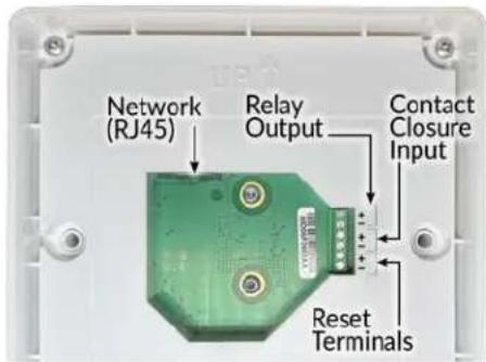
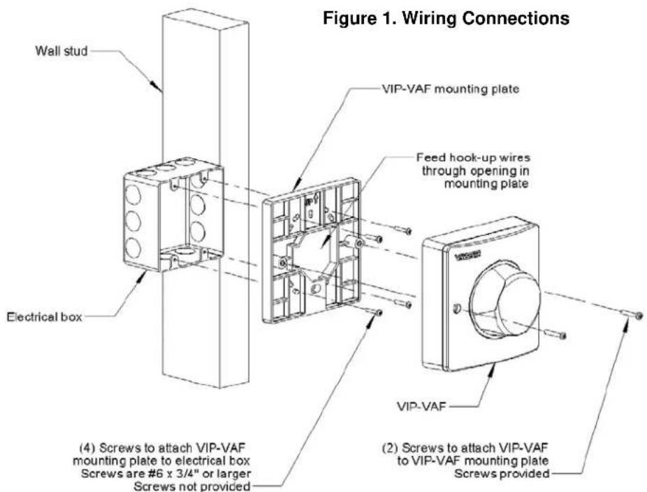
Figure 2. Indoor Installation
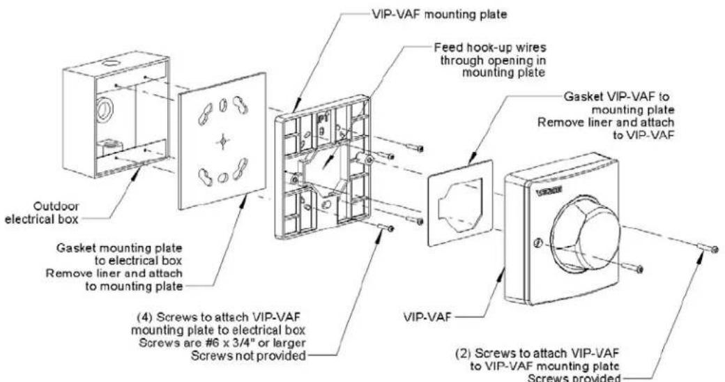
Figure 3. Outdoor Installation
- VIP-VAF-IC INFORMACAST® COMPLIANT MULTI-COLOR FLASHER
- INTRODUCTION
- SPECIFICATIONS
- FEATURES
- ACTIVATION METHODS
- INPUT/OUTPUT
- DIMENSIONS / WEIGHT
- NOMINAL POWER REQUIREMENTS
- ENVIRONMENT
- INSTALLATION
- OPERATION
- MOUNTING
- MANUFACTURERS' DEVICES. THEREFORE, IT MUST NOT BE INSTALLED WHERE THE FLASH FROM OTHER, NON-VALCOM FLASHERS MAY BE SEEN
- POWER CONNECTIONS
- NETWORK CONNECTION
- INPUT / OUTPUT CONNECTIONS
- SETUP
- RESET
- TECHNICAL ASSISTANCE
- WARRANTY
Marque : Valcom
Modèle : VIP-VAF-IC
Catégorie : Dispositif de signalisation lumineuse