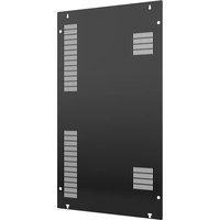
ODMBC-LG - Support mural pour écran Chief - Notice d'utilisation et mode d'emploi gratuit
Retrouvez gratuitement la notice de l'appareil ODMBC-LG Chief au format PDF.


| Marque | Chief |
| Modèle | ODMBC-LG |
| Type de produit | Support mural pour téléviseur |
| Utilisation recommandée | Téléviseurs LG de 55 à 85 pouces |
| Norme VESA compatible | Jusqu'à 600 x 400 mm |
| Capacité de charge maximale | 56 kg (125 lbs) |
| Matériau | Acier à haute résistance |
| Inclinaison | Fixe (non inclinable) |
| Rotation | Non rotatif |
| Distance du mur | 1,6 cm (5/8 pouce) |
| Dimensions (L x H) | 75,6 x 45,7 cm (29,75 x 18 pouces) |
| Poids du support | 4,5 kg (10 lbs) |
| Fixation murale | Vis et chevilles incluses pour béton et bois |
| Niveau à bulle intégré | Oui |
| Alimentation | Aucune (mécanique) |
| Entretien et nettoyage | Essuyer avec un chiffon doux et sec. Ne pas utiliser de produits abrasifs. |
| Sécurité | Installation obligatoire sur un mur porteur. Vérifier régulièrement le serrage des vis. |
| Pièces détachées et réparabilité | Vis de rechange disponibles auprès du fabricant. Support non réparable par l'utilisateur. |
| Garantie | 5 ans |
| Notice d'utilisation | Incluse au format PDF téléchargeable |
FOIRE AUX QUESTIONS - ODMBC-LG Chief
Questions des utilisateurs sur ODMBC-LG Chief
0 question sur cet appareil. Repondez a celles que vous connaissez ou posez la votre.
Poser une nouvelle question sur cet appareil
Téléchargez la notice de votre Support mural pour écran au format PDF gratuitement ! Retrouvez votre notice ODMBC-LG - Chief et reprennez votre appareil électronique en main. Sur cette page sont publiés tous les documents nécessaires à l'utilisation de votre appareil ODMBC-LG de la marque Chief.
MODE D'EMPLOI ODMBC-LG Chief
INSTALLATION INSTRUCTIONS
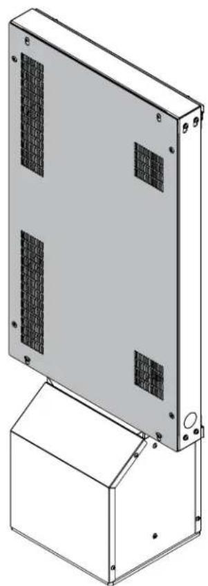
Velocity™ Outdoor Pedestal Rear Cover (LG)
DISCLAIMER
Legrand | AV and its affiliated corporations and subsidiaries (collectively Legrand | AV), intend to make this manual accurate and complete. However, Legrand | AV makes no claim that the information contained herein covers all details, conditions or variations, nor does it provide for every possible contingency in connection with the installation or use of this product. The information contained in this document is subject to change without notice or obligation of any kind. Legrand | AV makes no representation of warranty, expressed or implied, regarding the information contained herein. Legrand | AV assumes no responsibility for accuracy, completeness or sufficiency of the information contained in this document.
Chief® is a registered trademark of Legrand AV Inc,
DEFINITIONS
WARNING: A WARNING alerts you to the possibility of serious injury or death if you do not follow the instructions.
CAUTION: A CAUTION alerts you to the possibility of damage or destruction of equipment if you do not follow the corresponding instructions.
MOUNTING SYSTEM: A MOUNTING SYSTEM is the primary product designed by Chief® to mount the projector or display.
ACCESSORY: An ACCESSORY is any product designed by Chief® to complement the primary mounting system either by mounting any supporting components or enhancing the mounting capabilities of the primary mounting system.
COMPONENT: A COMPONENT is any secondary product to be mounted to an accessory, i.e. speakers, CPU's, cameras, tablets, additional displays.

IMPORTANT SAFETY INSTRUCTIONS

WARNING: Failure to read, thoroughly understand, and follow all instructions can result in serious personal injury, damage to equipment, or voiding of factory warranty! It is the installer's responsibility to make sure all mounts/accessories are properly assembled and installed using the instructions provided.

WARNING: Use this accessory only for its intended use as described in these instructions. Do not use attachments not recommended by the manufacturer.

WARNING: Never operate this accessory if it is damaged. Return the mounting system to a service center for examination and repair.
NOTE: ODMBCLG has no user serviceable parts.
--SAVE THESE INSTRUCTIONS--
DIMENSIONS
![28.12 [714.3] 2X 4.50 [114.3] 2X 3.38 [85.7] 4.63 [117.5] 15.88 [403.2] 2X 45.97 [1167.5] 2X 38.25 [971.6] 4.63 [117.5] 15.88 [403.2] 2X 22.01 [559.2] 2X 26.25 [666.8]](/content/2026/07/1465086/images/c918103c3feaa2bbcb5dedf42a99e7ca398630593de75c917f9013fd8e58a6ac.jpg)
![7.50 [190.6] 5.37 [136.5] 5.25 [133.3] 37.50 [952.5]](/content/2026/07/1465086/images/db9df278187ffeeed49ce0e45494d3641794b6bc0b71694a31218e824ce32dd7.jpg)
![DIMENSIONS: INCHES [MILLIMETERS]](/content/2026/07/1465086/images/a7ae3b96131ab5363f1d734c4e83d737503b890246aade17ea9e915ffe38e316.jpg)
DIMENSIONS


DIMENSIONS: INCHES [MILLIMETERS]
LEGEND
 | Tighten Fastener |
| Apretar elemento de fijación | |
| Befestigungsteil festziehen | |
| Apertar fixador | |
| Serrare il fissaggio | |
| Bevestiging vastdraaien | |
| Serrez les fixations | |
 | Loosen Fastener |
| Aflojar elemento de fijación | |
| Befestigungsteil lösen | |
| Desapertar fixador | |
| Allentare il fissaggio | |
| Bevestiging losdraaien | |
| Desserrez les fixations | |
 | Phillips Screwdriver |
| Destornillador Phillips | |
| Kreuzschlitzschraubendreher | |
| Chave de fendas Phillips | |
| Cacciavite a stella | |
| Kruiskopschroevendraaier | |
| Tournevis à pointe cruciforme | |
 | Open-Ended Wrench |
| Llave de boca | |
| Gabelschlüssel | |
| Chave de bocas | |
| Chiave a punte aperte | |
| Steeksleutel | |
| Clé à fourche | |
 | By Hand |
| A mano | |
| Von Hand | |
| Com a mão | |
| A mano | |
| Met de hand | |
| À la main | |
 | Hex-Head Wrench |
| Llave de cabeza hexagonal | |
| Sechskantschlüssel | |
| Chave de cabeça sextavada | |
| Chiave esagonale | |
| Zeskantsleutel | |
| Clé à tête hexagonale |





TOOLS REQUIRED FOR INSTALLATION
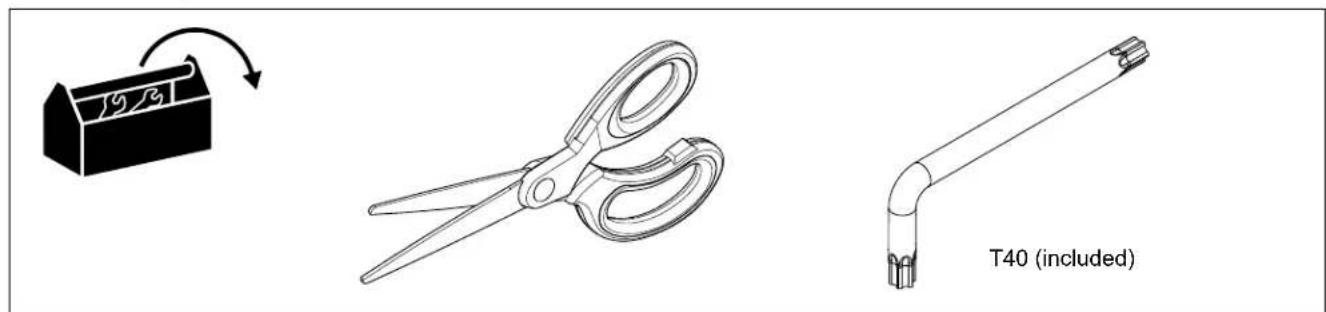
PARTS

Installation
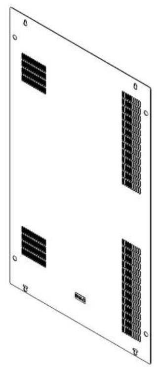
- Apply foam tape (D) to the edge of the partition (B).
- Partially install two M8 x 16mm Torx screws (E) to the inside of the frame. (See Figure 2)
- Position the slots in the partition (B) over the two M8 x 16mm Torx screws (E), then slide it towards the back of the display. Tighten the M8 x 16mm Torx screws. (See Figure 2)

Figure 1
- Apply foam tape (D) along the outside edges of the back cover (A). (See Figure 2)

Figure 2
- Loosen the four M8 x 20mm security screws from the rear of the frame. Leave approximately half of the threads exposed. (See Figure 3)

Figure 3
- Place the rear cover (A) over the frame. Position the exposed screws through the four slots in the corners of the cover, then lower the cover and hang it on the screws. (See Figure 4)
- Re-tighten the four M8 x 20mm security screws using the included T40 security hex key (C). (See Figure 4)
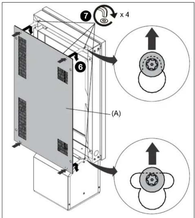
Figure 4
CHIEF®
A brand of □ legrand
8800-003451 Rev00
©2025 Legrand | AV
www.legrandav.com
05/2025
USA/International A 6436 City West Parkway, Eden Prairie, MN 55344
P 800.582.6480 / 952.225.6000
F 877.894.6918 / 952.894.6918
Europe A Franklinstraat 14, 6003 DK Weert, Netherlands
P +31 (0) 495 580 852
F +31 (0) 495 580 845
Asia Pacific A Office No. 918 on 9/F, Shatin Galleria
18-24 Shan Mei Street
Fotan, Shatin, Hong Kong
P 852 2145 4099
F 852 2145 4477


Marque : Chief
Modèle : ODMBC-LG
Catégorie : Support mural pour écran