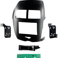
99-7014HG - Accessoire automobile Metra - Notice d'utilisation et mode d'emploi gratuit
Retrouvez gratuitement la notice de l'appareil 99-7014HG Metra au format PDF.


| Type de produit | Kit de montage pour autoradio |
| Marque | Metra |
| Modèle | 99-7014HG |
| Compatibilité | Honda Accord (2003-2007), Civic (2006-2011), CR-V (2007-2011) et autres sélectionnés |
| Matériau | Plastique ABS |
| Couleur | Noir brillant (High Gloss) |
| Dimensions | 178 x 102 mm (standard DIN) |
| Poids | Environ 0,2 kg |
| Installation | Insertion directe, sans modification |
| Outils nécessaires | Tournevis, clé à douille, outil de démontage de garniture |
| Contenu du kit | Cadre de montage, supports de fixation, vis, instructions |
| Fonctions principales | Adaptation d'un autoradio après-marché à la console d'origine |
| Entretien et nettoyage | Chiffon doux légèrement humide, éviter les solvants |
| Sécurité | Débrancher la batterie avant installation, suivre les instructions |
| Pièces détachées | Disponibles sur le site Metra (supports, vis de rechange) |
| Réparabilité | Kit non réparable, remplacer en cas de dommage |
| Garantie | 1 an contre les défauts de fabrication |
FOIRE AUX QUESTIONS - 99-7014HG Metra
Questions des utilisateurs sur 99-7014HG Metra
0 question sur cet appareil. Repondez a celles que vous connaissez ou posez la votre.
Poser une nouvelle question sur cet appareil
Téléchargez la notice de votre Accessoire automobile au format PDF gratuitement ! Retrouvez votre notice 99-7014HG - Metra et reprennez votre appareil électronique en main. Sur cette page sont publiés tous les documents nécessaires à l'utilisation de votre appareil 99-7014HG de la marque Metra.
MODE D'EMPLOI 99-7014HG Metra

Installation instructions for 99-7014
APPLICATIONS
See application list inside
Mitsubishi Outlander Sport 2011-2014 99-7014
KIT FEATURES
• ISO DIN radio provision with pocket
• Double DIN radio provision
• 99-7014B - Painted scratch resistant matte black
• 99-7014HG - Painted high gloss black
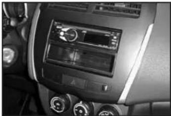
KIT COMPONENTS
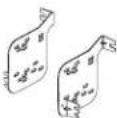
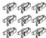
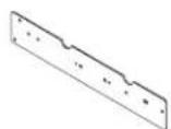
- A) Radio trim plate • B) Hazard control board • C) Double DIN brackets • D) Pocket • E) (9) Panel clips
- F) (7) #8 x 3/8" Phillips pan head screws • G) (4) #8 x 3/8" Phillips truss head screws
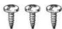
• H) (3) #4 x 3/8" Phillips pan head screws
A

BCDE


F

G

H

WIRING & ANTENNA CONNECTIONS (sold separately)
Wiring Harness:
• 70-7005 - Mitsubishi harness 2007-up
• MITO-02 - (2011-2013 models)
• MITO-03 - (2014 models)
Antenna Adapter:
- Not required
TOOLS REQUIRED
- Panel removal tool
- Phillips screwdriver
- Socket set
CAUTION: Metra recommends disconnecting the negative battery terminal before beginning any installation. All accessories, switches, and especially air bag indicator lights must be plugged in before reconnecting the battery or cycling the ignition.
NOTE: Refer to the instructions included with the aftermarket radio.
99-7014
Table of Contents
Dash Disassembly
- Mitsubishi Outlander Sport 2011-2014 ....2-4
Kit Assembly
- Radio trim panel assembly ....
- ISO DIN radio provision with pocket....6
- Double DIN radio provision 7
Mitsubishi Outlander Sport 2011-2014
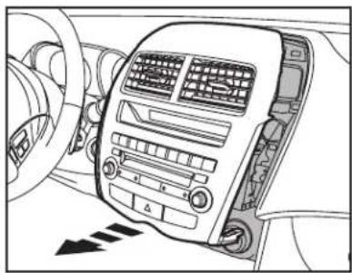
- Gently pry the radio control panel from the dash. Disconnect the harness and place panel aside. (Figure A)
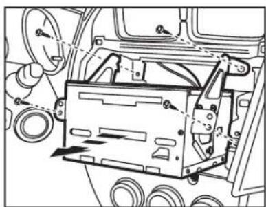
5 2. Remove (4) Phillips screws securing the radio chassis to the sub dash and remove radio. (Figure B)
Continued on next page
(Figure A)
(Figure B)

Dash Disassembly 99-7014
Mitsubishi Outlander Sport 2011-2014
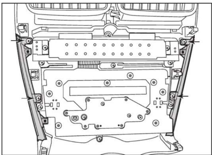
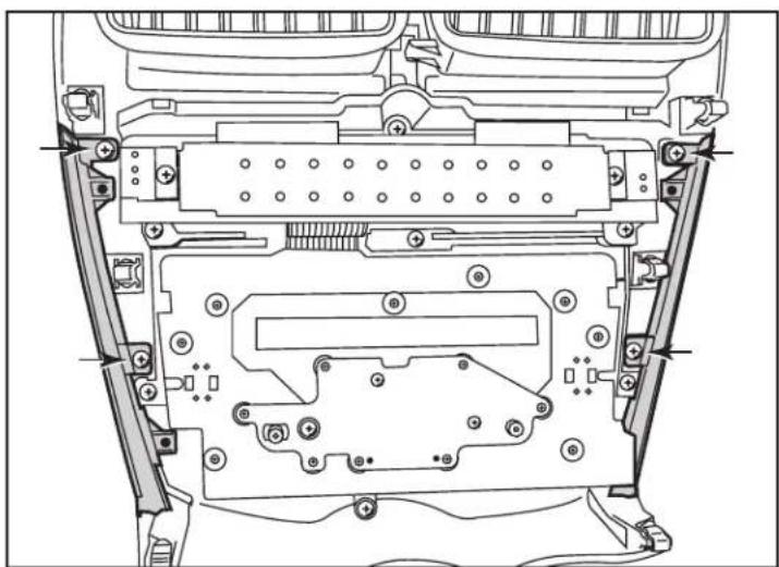
- Remove (4) Phillips screws securing silver trim panels to radio control panel and place aside for kit assembly. (Figure C)
(Figure C) (Figure D)
- Remove (16) #1 Phillips screws securing the circuit board to the radio control panel. Place (2) screws aside for later in kit assembly. (Figure D)
Continued on next page


Dash Disassembly 99-7014
Mitsubishi Outlander Sport 2011-2014
- Remove (11) #2 Phillips screws securing the circuit board to the radio control panel. Remove the circuit board from the radio control panel. (Figure E)
- Remove the hazard button from the radio control panel. Place hazard button aside for kit assembly. (Figure F)

(Figure D) (Figure F)
- Remove (3) #2 Phillips screws from the LCD filter panel. Unclip vents and place aside for kit assembly. (Figure G)
- Remove factory airbag and seat belt labels from factory panel and place aside for kit assembly.
Continue to kit assembly

(Figure F)


Kit Assembly 99-7014
Radio trim panel assembly
- Install panel clips on radio trim panel. (Figure A)
- Clip factory vents removed earlier into radio trim panel. (Figure A)
- Secure silver trim panels to radio trim panel with (4) included #8 3/8" Phillips pan head screws. (Figure A)
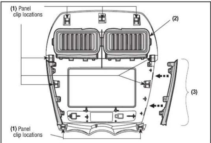
(Figure A)
- Secure factory hazard button to radio trim panel with (3) included #8 3/8" Phillips pan head screws. (Figure B)
- Secure circuit board to factory hazard button with (2) Phillips screws removed earlier. (Figure C)
- Continue securing the circuit board to radio trim panel with (3) included #4 3/8" Phillips pan head screws. (Figure D)
- Place airbag and seatbelt labels removed earlier on radio trim panel. Continued on next page


(Figure C)

(Figure D)(Figure B)
Dash Disassembly 99-7014
ISO DIN radio provision with pocket
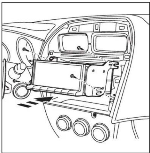
- Mount the radio to the brackets with screws included with radio. (Figure A)
- Mount the radio brackets to the pocket with the screws supplied. (Figure A)
- Locate the factory wiring harness and antenna plug in the dash. Metra recommends using the proper mating adapters from Metra and/or AXXESS.
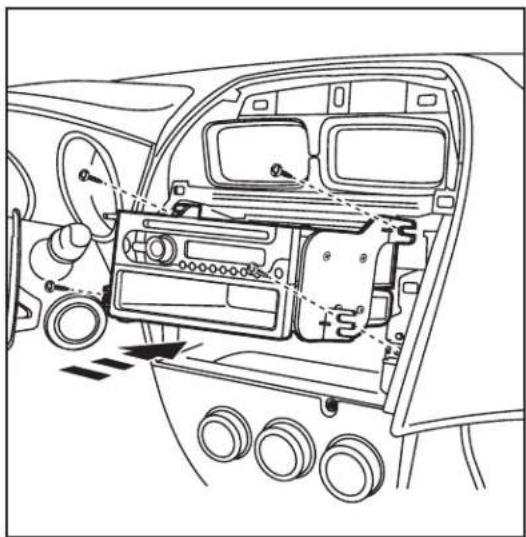
- Mount assembly into the sub dash. (Figure B)
- Reassemble dash in reverse order of disassembly using 99-7014 trim panel instead of factory panel.
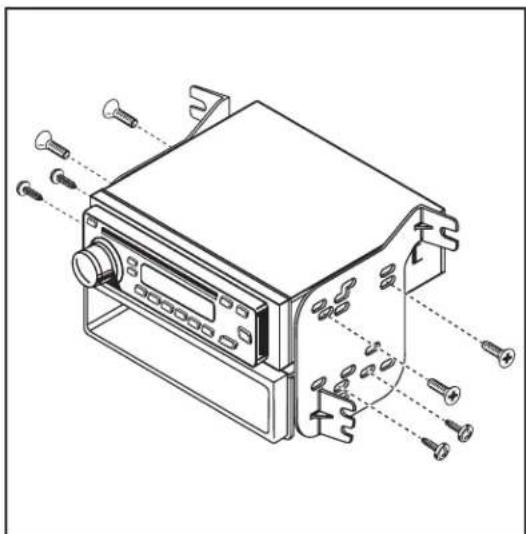
(Figure A) (Figure B)

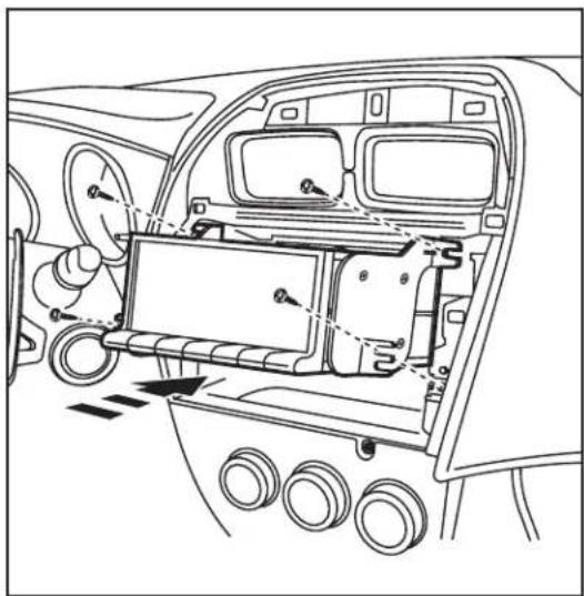
Double DIN radio provision
- Mount the radio to the double DIN brackets with screws included with radio. (Figure A)
- Locate the factory wiring harness and antenna plug in the dash. Metra recommends using the proper mating adapters from Metra and/or AXXESS.
- Mount assembly into the sub dash. (Figure B)
- Reassemble dash in reverse order of disassembly using 99-7014 trim panel instead of factory panel.
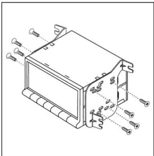
(Figure A) (Figure B)

Installation instructions for 99-7014

KNOWLEDGE IS POWER
Enhance your installation and fabrication skills by paralling in the most recognized and supported
mobile electronics school in our industry.
Log onto www.installerinstitute.com or call
606-354-6782 for more information and take steps toward a better tomorrow.

Metra recommends MECP
certified technicians

Instrucciones de instalación para 99-7014
APLICACIONES
Lista de aplicaciones dentro
Mitsubishi Outlander Sport 2011-2014 99-7014
CARACTERÍSTICAS DEL KIT
• Provisión de radio ISO DIN con bolsillo
• Provisión de radio doble DIN
• 99-7014B - Pintada en negro mate
• 99-7014HG - Pintada en alto brillo negro

COMPONENTES DEL KIT
- A) Panel decorativo para radio • B) Tablero de control de peligros • C) Soportes doble DIN • D) Bolsillo
- E) Sujetadores de panel • F) (7) tornillos Phillips de cabeza troncocónica #8 de 3/8" • G) (4) tornillos Phillips de cabeza segmentada #8 de 3/8" • H) (3) tornillos Phillips de cabeza troncocónica #4 de 3/8"
ABCDE



F

G

H
CABLEADO Y CONEXIONES DE ANTENA
Arnés de cableado:
(se venden por separado)
• 70-7005
• MITO-02 - (2011-2013 models)
• MITO-03 - (2014 models)
Adaptador de antena:
- No se requiere
HERRAMIENTAS REQUERIDAS
- Herramienta de remoción de panel
- Destornillador Phillips • Llave para dados
PRECAUCIÓN: Metra recomienda desconectar el terminal negativo de la batería antes de comenzar cualquier instalación. Todos los accesorios, interruptores y, especialmente, las luces indicadoras de airbag deben estar enchufados antes de volver a conectar la batería o comenzar el ciclo de ignición.
NOTA: Remítase a las instrucciones incluidas con el radio de postventa.
99-7014
Indice
Desmontaje del tablero
- Mitsubishi Outlander Sport 2011-2014 ....2-4
Ensamble del kit
- Panel de moldura para radio ensamble 5
- Provisión de radio ISO DIN con bolsillo 6
- Provisión de radio doble DIN.... 7
Mitsubishi Outlander Sport 2011-2014
- Con delicadeza retire el panel de control del radio del tablero. Desconecte el arnés y ponga el panel a un lado. (Figura A)
- Retire los tornillos Phillips (4) asegurando el chasis del radio al sub tablero y retire la unidad. (Figura B)
Continúa en la página

(Figura A)

(Figura B)
Desmontaje del tablero 99-7014
Mitsubishi Outlander Sport 2011-2014
- Retire los tornillos Phillips (4) asegurando los paneles decorativos plateados al panel de control del radio y déjelos a un lado para el ensamble del kit. (Figura C)
(Figura C) (Figura D)
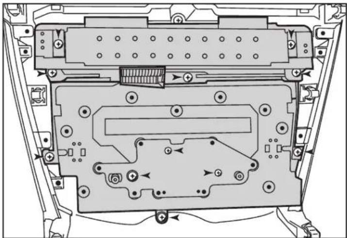
- Retire los tornillos Phillips #1 (16) asegurando el tablero de circuito al panel de control del radio. Deje a un lado los tornillos (2) para el ensamble posterior del kit. (Figura D)
Continúa en la página

Desmontaje del tablero 99-7014
Mitsubishi Outlander Sport 2011-2014
- Retire los tornillos Phillips #2 (11) asegurando el tablero de circuito al panel de control del radio. Retire el tablero de circuito del panel de control del radio. (Figura E)
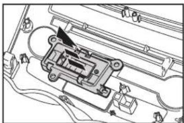
- Retire el botón de las luces intermitentes del panel de control del radio. Deje a un lado el botón de las luces intermitentes para el ensamble del kit. (Figura F)
(Figura D) (Figura F)
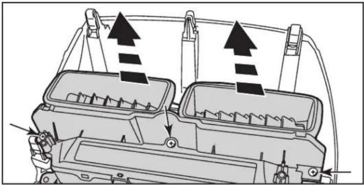
- Retire los tornillos Phillips #2 (3) del panel de filtro de LCD. Quite las rejillas de ventilación y déjelas a un lado para el ensamble del kit. (Figura G)
- Retire las etiquetas de fábrica de la bolsa de aire y del cinturón de seguridad del panel de fábrica y déjelas a un lado para el ensamble del kit.
Continúe al ensamble del kit
(Figura F)

Ensamble del kit 99-7014
Panel de moldura para radio ensamble
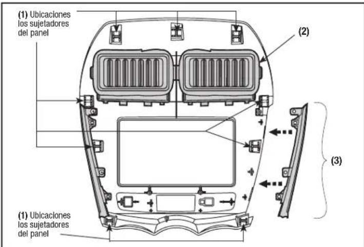
- Instale los sujetadores del panel en el panel decorativo del radio. (Figura A)
- Sujete las rejillas de ventilación que se retiraron previamente al panel decorativo. (Figura A)
- Asegure los paneles decorativos plateados al panel decorativo del radio con los tornillos de cabeza troncocónica Phillips (4) #8 de 3/8" incluidos. (Figura A)
(Figura A)
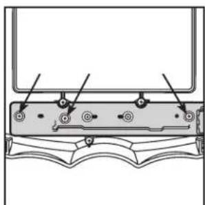
- Asegure el botón de las luces intermitentes de fábrica al panel decorativo de radio con los tornillos de cabeza troncocónica Phillips (3) #8 3/8" incluidos. (Figura B)
- Asegure el tablero de circuito al botón de las luces intermitentes de fábrica con los tornillos Phillips (2) retirados previamente. (Figura C)
- Continúe asegurando el tablero de circuito al panel decorativo del radio con los tornillos de cabeza segmentada Phillips (3) #4 de 3/8" incluidos. (Figura D)
- Coloque las etiquetas de la bolsa de aire y de los cinturones de seguridad retiradas anteriormente en el panel decorativo del radio.
Continúa en la página


(Figura C)
(Figura D)(Figura B)
Desmontaje del tablero 99-7014
Provisión de radio ISO DIN con bolsillo
- Monte el radio en los soportes con los tornillos incluidos con la unidad. (Figura A)
- Monte los soportes del radio al bolsillo con los tornillos suministrados. (Figura A)
- Ubique el arnés de cableado de fábrica y el tapón de la antena en el tablero. Metra recomienda el uso de adaptadores adecuados de acoplamiento de Metra y/o AXXESS.
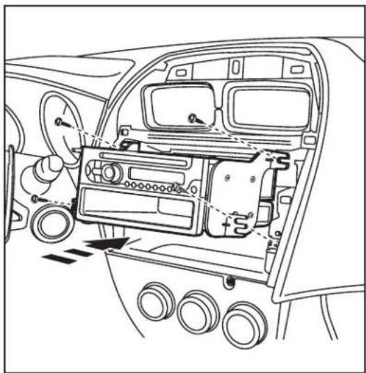
- Monte el ensamble en el sub tablero. (Figura B)
- Vuelva a armar el tablero en orden inverso al desensamble, usando el panel decorativo 99-7014 en lugar del panel de fábrica.

(Figura A) (Figura B)

Provisión de radio doble DIN
- Monte el radio en los soportes doble DIN con los tornillos incluidos con la unidad. (Figura A)
- Ubique el arnés de cableado de fábrica y el tapón de la antena en el tablero. Metra recomienda el uso de adaptadores adecuados de acoplamiento de Metra y/o AXXESS.
- Monte el ensamble en el sub tablero. (Figura B)
- Vuelva a armar el tablero en orden inverso al desensamble, usando el panel decorativo 99-7014 en lugar del panel de fábrica.

(Figura A) (Figura B)

Instrucciones de instalación para 99-7014


EL CONOCIMIENTO ES PODER
Mejore sus habilidades de instalación y fabricación inscribiéndose en la escuela de dispositivos electrónicos móviles más reconocida y respetada de nuestra industria. Registrese en www.installerinstitute.com o llame al 800-354-6782 para obtener más información y avance hacia un futuro mejor.

Metra recomienda técnicos con certificación del Programa de Certificación en Electrónica Móvil (Mobile Electronics Certification Program, MECP).
- APPLICATIONS
- MITSUBISHI OUTLANDER SPORT 2011-2014 99-7014
- KIT FEATURES
- KIT COMPONENTS
- WIRING & ANTENNA CONNECTIONS (SOLD SEPARATELY)
- TOOLS REQUIRED
- TABLE OF CONTENTS
- DASH DISASSEMBLY
- KIT ASSEMBLY
- MITSUBISHI OUTLANDER SPORT 2011-2014
- DASH DISASSEMBLY 99-7014
- RADIO TRIM PANEL ASSEMBLY
- ISO DIN RADIO PROVISION WITH POCKET
- DOUBLE DIN RADIO PROVISION
- CARACTERÍSTICAS DEL KIT
- COMPONENTES DEL KIT
- CABLEADO Y CONEXIONES DE ANTENA
- HERRAMIENTAS REQUERIDAS
- INDICE
- DESMONTAJE DEL TABLERO
- ENSAMBLE DEL KIT
- DESMONTAJE DEL TABLERO 99-7014
- PANEL DE MOLDURA PARA RADIO ENSAMBLE
- PROVISIÓN DE RADIO ISO DIN CON BOLSILLO
- PROVISIÓN DE RADIO DOBLE DIN
Marque : Metra
Modèle : 99-7014HG
Catégorie : Accessoire automobile