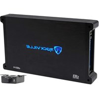
dB14 - Recepteur Rockville - Notice d'utilisation et mode d'emploi gratuit
Retrouvez gratuitement la notice de l'appareil dB14 Rockville au format PDF.


| Type de produit | Récepteur audio stéréo |
| Marque | Rockville |
| Modèle | dB14 |
| Dimensions (L x H x P) | 430 x 100 x 300 mm |
| Poids | 5 kg |
| Alimentation | 110-240 V AC, 50/60 Hz |
| Puissance de sortie | 100 W x 2 canaux (sous 8 ohms) |
| Impédance des enceintes | 4-8 ohms |
| Entrées audio | 2 x RCA, 1 x optique, 1 x coaxial |
| Sorties | Enceintes (A/B), caisson de basses, casque |
| Connectivité sans fil | Bluetooth 5.0 |
| Radio FM | Oui, avec 30 présélections |
| Fonctions principales | Amplification, sélection source, réglages tonalité |
| Entretien et nettoyage | Dépoussiérer avec un chiffon sec et doux |
| Sécurité | Ne pas exposer à l'eau ou à l'humidité excessive |
| Pièces détachées et réparabilité | Disponibles sur demande auprès du revendeur |
| Informations générales | Notice d'utilisation téléchargeable au format PDF |
FOIRE AUX QUESTIONS - dB14 Rockville
Questions des utilisateurs sur dB14 Rockville
0 question sur cet appareil. Repondez a celles que vous connaissez ou posez la votre.
Poser une nouvelle question sur cet appareil
Téléchargez la notice de votre Recepteur au format PDF gratuitement ! Retrouvez votre notice dB14 - Rockville et reprennez votre appareil électronique en main. Sur cette page sont publiés tous les documents nécessaires à l'utilisation de votre appareil dB14 de la marque Rockville.
MODE D'EMPLOI dB14 Rockville
ROCKVILLE
dB Series
CLASS D MONO 2-OHM AMPLIFIERS
OWNER'S MANUAL
ATTENTION: WATCH THIS VIDEO BEFORE FIRST USE!
Who reads manuals?
Scan the QR code or go to the SKUs to access how-to video(s), the owner's manual, and other important information you may need to get the most out of your item.
If you prefer written instructions, please read ahead!
With Rockville you get many options.

rockvillesupport.com/dB12

rockvillesupport.com/dB13

rockvillesupport.com/dB14

rockvillesupport.com/dB15

rockvillesupport.com/dB16
Missing items? If you ordered a bundle that includes more than one product and you are missing part of your bundle then it just means your order shipped from two different warehouses. You will receive the remaining items very soon. If you have any concerns or inquiries, feel free to call our customer support center at 1-646-758-0144, 24 hours a day/7 days a week.
Introduction
Thank you for purchasing this Rockville dB Series Class D Mono Amplifier. Over the years, the technology used to create audio amplifiers has grown by leaps and bounds. Our competition is satisfied with just continuing to build the same units year after year without thought for improvement, but not Rockville. We consider it our mission to use our expertise in developing the latest technologies and to bring you the absolute best-sounding amplifiers on the market and of course at a reasonable price. You will be amazed at the quality and power that these new amps offer.
We have spared no expense in designing these amplifiers, creating the most rugged, reliable, powerful, and best-performing amplifiers. In fact, we are so sure of the quality, we backup every dB Series amplifier with a one-year warranty, which exemplifies our commitment to the end user. (See enclosed warranty vehicled for details.)
Please read this installation guide fully for proper use of your dB Series Class D Mono Amplifier. Read this entire guide fully before attempting your installation. Should you need assistance, please call our technical help line at 1-646-758-0144, 24 hours a day/7 days a week.
IMPORTANT SAFETY INSTRUCTIONS

WARNING: BE AWARE! Use of this amplifier at extreme high volumes for extended periods of time may cause hearing loss and/or hearing damage. Your ability to hear necessary sounds will be impaired. Always keep your sound volume at reasonable levels when operating your vehicle.
- When installing the amplifier, secure it tightly. An unmounted amplifier in your vehicle can cause serious injury to passengers and damage if it is set in motion by an abrupt maneuver or sudden stop.
- To reduce risk of electric shock, never open the unit. There are no serviceable parts; refer service to Rockville Audio.
- Please ensure that the unit is situated in a properly ventilated area.
Installation
Please note: dB15 shown as an example. Installation instructions apply to all mono models.
Installation Basics
Before you begin your installation, disconnect the NEGATIVE(-) terminal from your vehicle's battery. This safety precaution will avoid possible short circuits while wiring your amplifier. Rockville amplifiers will operate on 12-volt negative ground systems only. It is recommended that you lay out your sound system design on paper first. This will help you during the installation so that you will have a wiring flowchart and do not miss-wire any of your components.
Mounting The Amplifier
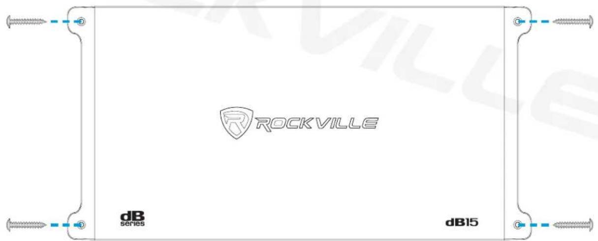
dB Series amplifiers feature four mounting tabs located at the amplifiers four corners. Never install an amplifier in the engine compartment or on the firewall. Lay down the amplifier and mark the location of the mounting holes. It can be installed either horizontally or vertically. Remove the amplifier and drill pilot holes for the screws. Be sure to watch for your gas tank, gas lines, and electrical lines. Do not drill or mount any screws where they might penetrate the gas tank. Place the amplifier and secure it to the mounting surface using the supplied screws. Please be sure to leave breathing room around the amplifier heat sink so that it can efficiently dissipate the heat it produces.
- AS CONNECTIONS CAN WORK LOOSE DUE TO VEHICLE VIBRATIONS DURING NORMAL OPERATION, WE RECOMMEND PERIODICALLY TIGHTENING ALL POWER AND GROUND CONNECTIONS.
• DO NOT OVERTIGHTEN THE SCREWS.
Wiring
Please note: dB15 shown as an example. Wiring instructions apply to all mono models.
- Make sure to disconnect the NEGATIVE (-) terminal from your vehicle's battery.
- Attach an 0-gauge or heavier wire to the amplifier screw terminal marked GND. The connection should be as close to the amp as possible (20 feet or less). Connect the ground wire to a metal part of the vehicle's chassis, making sure that there is no paint or other insulator blocking a good ground connection. When installing multiple amplifiers, mount them in close proximity so that they can all share the same ground point.
- Connect the remote terminal to the head unit's remote output using 18-gauge or heavier wire. This connection is responsible for turning the amplifier on and off with the rest of the system. If there is no dedicated remote output, make this connection to the power antenna lead. Should your head unit not have any turn-on leads, you can wire the remote terminal to an accessory lead, which turns the amplifier on with your vehicle's ignition.
- Use 0-gauge or heavier wire to connect the screw terminal marked +12V to the battery's POSITIVE (+) terminal. In order to protect the battery and electrical systems of your vehicle, add an in-line fuse holder within 18" of the battery. This in-line fuse offers protection against damage from short circuits. The power wire should terminate in a large ring terminal connected directly to the POSITIVE (+) terminal. An optional second fuse can be installed closer to the amplifier for additional protection to the amplifier itself. If installing multiple amplifiers, install a distribution block near their location and, using a 0-gauge wire, connect the block to the in-line holder that is connected to the battery.
- Insert fuse(s) into the in-line fuse holder(s) and check that all connections are properly secured.
- Before powering up the system, set all the amplifier's level controls to minimum, the crossover/setting switches to the desired position, and the head unit's volume to 75%.
We have received amplifiers back to our service department with melted power/ground terminals caused by a bad ground connection. When there is a lack of good ground, heat builds up at the contact screws of the amplifier terminal. Over time the heat generated will begin to melt the terminal. It is a good practice to feel the power and ground wires near the amplifier after using the amp for a while. If the wires feel hot to the touch, you probably have a bad or loose connection. If after adjusting your connections the wires still feel hot, you should upgrade to the next heaviest gauge wire. As connections can work loose due to vehicle vibrations, we recommend periodically tightening all power and ground connections.

ATTENTION
FOR BEST PERFORMANCE BE SURE TO STRIP YOUR WIRE, AT MINIMUM, AS PER THE DIAGRAM BELOW.
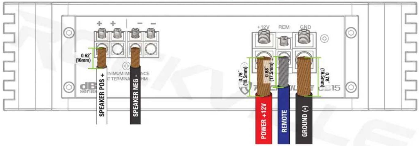
TERMINAL DIAMETER: POWER = Φ0.33in (8.4mm), REM = Φ0.15in (3.9mm), SPEAKER = Φ0.15in (3.9mm) TERMINAL DEPTH: POWER = 0.76in (19.5mm), REM = 0.68in (17.5mm), SPEAKER = 0.62in (16mm)
TIGHTEN SET SCREWS TO ENSURE WIRES ARE PROPERLY SECURED TO THE TERMINAL.
MAKE SURE THE WIRE IS PROPERLY SEATED

RUBBER SHEATHING SHOULD BE FLUSH AGAINST THE TERMINAL HOUSING.
Settings
Adjusting the System
- Once the system is operational, set all crossover points to the approximate settings. In the case of a basic subwoofer system, set the Low Pass filter crossover at 100Hz or so. Set the Bass EQ to 0dB. Turn the controls using a small flathead screwdriver. Do not apply any pressure while turning as this might break the control unit.
- Set the amplifier's Input Sensitivity using the control accessible on the side of the amplifier marked INPUT LEVEL (gain). Turn it counterclockwise to the MIN position. Adjust your head unit's volume gain to the maximum it can go before signal distorts or to the loudest gain, which is usually about 75% – 85% on most head units (you can also use an oscilloscope to see at what gain level your head unit distorts). When you begin to hear distortion, back down one notch. Now turn the INPUT LEVEL control on the amp clockwise until you hear distortion, then turn it counterclockwise by a notch or until the distortion is gone. The amp's input sensitivity is now set. It is helpful to have a second person to help you set the gain. When setting up a multi-amp system, set each amplifier's level controls separately. Start off with the bass amplifier, then adjust the highs amplifier's level control to match. Please note that the level control of any vehicle amplifier should not be mistaken for a volume control. It is a sophisticated device designed to match the output level of your source unit to the input level of the amplifier. Do not adjust the amplifier level to maximum unless your input level requires it. Your system can also be extremely sensitive to noise when the input level is set to maximum and does not match your input signal. These adjustments need to be made only once when first setting up the system.
- Once you are satisfied with the level control settings, use any equalizer controls to adjust the system's tonal level for personal preference. Keep in mind that after equalizing you may have to go back and reset the amplifier's level controls.
If your unit has been professionally installed, please do not change the gain settings set by the installer. He or she is the professional!
Audio Preamp Input
This amplifier features RCA preamp inputs. Run RCA cables from your sound source to the amplifier's inputs. We suggest you use high-quality, shielded RCA patch cords to help reduce and eliminate unwanted electrical noise to your system. Use good quality RCA interconnect cables. Cheaper cables usually have poor shielding that can cause interference pickup.
Using the Built-In Low Pass Electronic Crossover
dB Mono Block amplifiers feature a 12dB per octave fully adjustable crossover with differential circuitry.
The knob marked LOW PASS will control the low-pass frequencies from 50Hz – 250Hz. A frequent error made is setting the low-pass frequency too low, especially when using vented subwoofer enclosures. We recommend that for most installations you set the frequency knob between 80Hz – 150Hz depending on your preference and the rest of your audio system.
Using the Subsonic High Pass Filter
Subsonic frequencies are very low and can cause damage to your subwoofers. The Subsonic High Pass Filter will allow you to attenuate any frequencies below the set limit.
Using the Phase Shift
The Phase Shift control synchronizes the phase of your subwoofer output to that of the other speakers in the vehicle. It can be set to 0 or 180 degrees. Set the amp to 0 and listen to a track with some bass. Now set the control to 180 degrees, listen to the same track, and see if the bass output improves or becomes worse. Set the switch to the setting which achieves the best results.
Sealed Enclosures
Sealed boxes are tuned by enclosure volume: larger enclosures tune lower; smaller enclosures tune higher. Subsonic frequencies can cause damage to your woofer as they cause it to play below the enclosure's tuning, forcing it to the limits of its excursion and making it expend a lot of energy. To avoid damage to your woofer, set the Subsonic HPF to 25Hz – 35Hz.
Ported Enclosures
The enclosure's port should be tuned to a certain frequency so that the enclosure is capable of playing all frequencies above that tuning. The enclosure can play below that frequency, but only half and an octave before the cone starts to overextend. Hence, set the Subsonic HPF to half an octave below the tuned frequency.
Here is a simple formula to help you figure out the proper Subsonic HPF setting for your particular ported enclosure. Keep in mind that one octave up is double the frequency and one octave down is half the frequency:
-
Divide the tuning frequency of your port by 4.
-
Now subtract the quotient (answer) of Step1 from the port's tuning frequency. This is half an octave lower than your tuning frequency.
Example:
Port tuning frequency is 46Hz:
-
46Hz ÷ 4 = 11.5Hz (half an octave lower)
-
46Hz - 11.5Hz = 34.5Hz (Round up to 35Hz.) This is half an octave lower than 46Hz.
Please note: The subsonic filter is NOT a cutoff. It has a roll-off slope that will attenuate the frequency it is set to. Attenuation will increase as the frequencies get lower, meaning the power to the woofer decreases at the filtered frequencies, which reduces excursion and the potential for damage.
Subsonic filters have steep slopes such as 3rd or 4th order (18 or 24dB/Oct) so they can be set as close to your half-octave frequency as possible, or 25Hz – 35Hz sealed, without losing power in the surrounding frequencies.
Input Configurations
Please note: dB15 shown as an example. Configurations apply to all mono models.
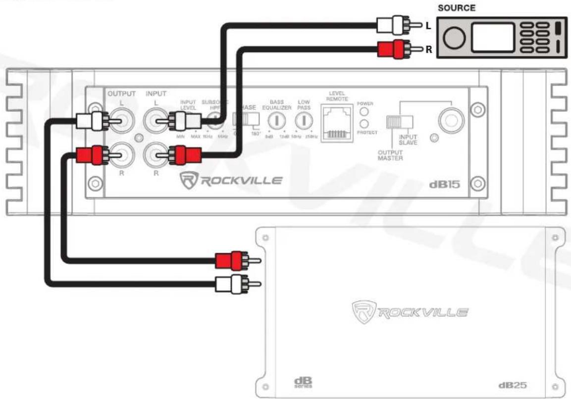
Connect your head unit's RCA outputs to the amplifier's Left and Right RCA input jacks. This amplifier features RCA preamp line outputs for feeding a full-range signal to a secondary full-range dB Series amp in a multi-amp system.
Output Configurations
Please note: dB15 shown as an example. Configurations apply to all mono models.
These amps are 2-ohm stable mono block amplifiers. No matter how many woofers you choose to wire up to these models, the final impedance should not fall below 2 ohm. Please see pages 14 and 15 for various speaker impedance configurations. The dual positive and negative terminals are connected in parallel inside the amplifier. Connecting two speakers, each to one set of positive and negative terminals, will result in a parallel speaker connection. If connecting only one pair of speaker wires, it is not necessary to use both sets of connections.

Twin Amp Bridging (dB14, dB15, dB16 only)
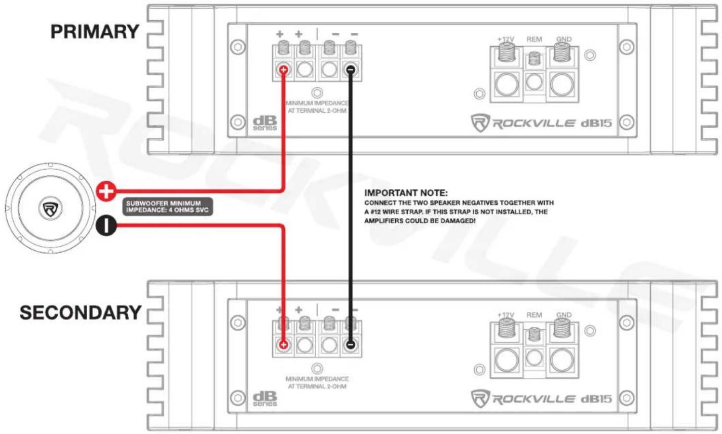
The dB14, dB15, and dB16 can be bridged together for double the power output into a single 4-ohm load. When bridging two amplifiers together, the final impedance load of the bridged amplifiers should be no lower than 4 ohms. Double power will occur at 4 ohms. Input the head unit signal into the PRIMARY amplifier and set the Bridged Mode switch to Output Master. Use a MONO RCA to RCA cable to send the fully processed signal from the PRIMARY amplifier to the SECONDARY amplifier and set the Bridged Mode switch on that amp to Input Slave. Do not input any signal to the Slave amplifier's RCA inputs. All settings will be controlled by the PRIMARY amplifier including input gain levels. There is no need to gain-match the two amplifiers, it will occur automatically. The remote dash bass control should be plugged into the Master amplifier and it will control both amplifiers. This same input/output control system can be utilized when daisy-chaining two amplifiers to two independent 2-ohm woofers as long as you don't bridge the two amplifier's outputs together. PRIMARY amplifier's positive (+) speaker terminal should be wired to the positive terminal of the subwoofer. SECONDARY amplifier's positive (+) speaker terminal should be wired to the negative terminal of the subwoofer. Connect a heavy gauge wire (12-Gauge) between the negative (-) terminal of the PRIMARY amplifier and the negative (-) terminal of the SECONDARY amplifier. When daisy-chaining two amplifiers for independent woofers, wire up the the woofers as you would typically wire them when installing individual systems, even down to 2-ohm. By using the PRIMARY/SECONDARY input configuration you gain the advantage of having one amplifier's preamp section control both amplifiers, eliminating the need to gain-match and crossover match your system between amplifiers.
You can only bridge two of the same amplifiers together. DO NOT BRIDGE DIFFERENT MODELS TOGETHER.

Features
Bass Equalization Circuitry
A narrow "Q" peaking equalization circuit is included in the amplifiers. The equalization system is preset at 45Hz. The equalizer control allows you to add up to 12dB of bass boost. Utilize the bass equalizer to tailor your bass response to your system's needs. Make sure your speakers can handle the extra power output! It would be foolish to add 12dB of gain to low excursion 8" and 10" subwoofers or mid ranges and tweeters. It's a sure way to blow your speakers.
Audio Output Section
The audio output sections of the dB Series mono block amps feature rugged, fast-switching MOSFETs.
Power and Protection Circuitry
These amplifiers feature our unique IC-controlled protection circuitry. This sophisticated circuit constantly monitors the heat sink internal temperature and various voltages, adjusting the amp automatically and protecting it from dangerous conditions. The two LEDs located on the side of the amplifier provide indication of the amplifier status. The POWER LED will light when the amplifier is receiving proper power, ground, and remote voltages, and the IC-monitoring sequence indicates the amp is functional. In case the amplifier encounters a diagnostic condition as listed below, the PROTECT LED will light indicating a diagnostic condition. When a diagnostic condition is sensed, the amplifier will then turn into self-preservation mode and if the cause of the diagnostic condition is not corrected will eventually shut down. There are certain critical diagnostic conditions that will turn the amplifier off immediately.
Thermal Protection: When the amplifier reaches an unsafe operating temperature of 80 degrees Celsius, the amplifier will turn off. Once the amplifier cools down to a safe temperature, it will automatically turn on again. If you live in a hot climate, we suggest installing additional cooling fans in your trunk to exhaust the hot air that can build up in the trunk. This will help keep the ambient temperature in the trunk as low as possible so that your amps work flawlessly and without any musical interruption.
Speaker Short Circuit Protection: Should your speakers short circuit due to voice coil burn out, or should the amplifier sense an impedance too low to handle, the protection LED will light, indicating a diagnostic condition. Turn off your system, disconnect one speaker at a time, and try to determine which speaker might be faulty. Correct the condition and restart the amplifier. You must reset the amplifier by turning it OFF and then ON again by the Remote power connection after correcting a diagnostic condition. (Turn your radio off and then on again.) Input Overload Protection: This circuit will either shut down the amplifier completely or make the amplifier spurt on and off indicating that it is in a diagnostic condition. Turn the system off and reduce the gain on the amplifier or volume from your head unit. This should result in a corrected condition.
DC Offset Protection: Should any DC voltage try to enter the amplifier via the speaker terminals it will cause the amplifier to shut down and not operate until this condition is remedied. This circuit will also protect damaging high DC voltages from reaching your speakers should your amplifier ever malfunction.
PLEASE NOTE: You must reset the amplifier by turning it OFF and then ON again after correcting a diagnostic condition (turn your radio off and then on again). If the amplifier stays in protection after a reset, it is most likely faulty.
Mute Circuit
This is an anti-thump, mute and delay circuit that eliminates irritating, speaker-damaging turn-on and turn-off transients normally experienced with less expensive amplifiers.
Bass Remote
The dash-mounted bass remote allows you to control the amplifier's bass level from the comfort of the driver's seat. It features a power LED which indicates the unit is receiving power and operating nominally.
Battery Voltage
Rockville dB Series amplifiers are rated and regulated to 13.8 volts and below. Increasing voltage to 14.4 volts will increase the power output of the amplifier in the same proportion. Maximum input voltage is 14.4 volts while the minimum voltage is 12 volts.
Additional Features
• High-Speed MOSFET Power Supply
• Optical Coupler Class "D" Technology
• Fully Adjustable 12dB/Octave Crossover with Differential Circuitry
- Low Pass: 50Hz - 250Hz
- Subsonic Filter: 15Hz - 55Hz
• Fully Adjustable 12dB Bass Equalizer
- Mute and Delay Soft Start System
- Phase Control Switch
• RCA Preamp Line Output
• Master/Slave Amplifier Daisy Chain and Bridging Capability (dB14, dB15, and dB16 only)
- Remote Dashboard Subwoofer Control
• Full IC-Controlled Protection Circuitry
• Status Mode LED Indicator
• 8 Volt Preamp Circuitry
Specifications
dB12
• Dyno Certified RMS Power Ratings:
2 Ohm: 500 Watts x 1 Channel <1% THD+N
4 Ohm: 300 Watts x 1 Channel <1% THD+N
- Peak Power:
2 Ohm: 2000 Watts x 1 Channel
4 Ohm: 1200 Watts x 1 Channel
• Minimum THD at Rated Power: <0.1%
• Frequency Response: 15Hz – 250Hz
• S/N Ratio: >90dB
• Damping Factor: >150 @ 100Hz
- 60 Amp Maxi Fuse
• Dimensions (W x H x L): 9" x 2.4" x 13.1"
dB13
• Dyno Certified RMS Power Ratings:
2 Ohm: 750 Watts x 1 Channel <1% THD+N
4 Ohm: 450 Watts x 1 Channel <1% THD+N
- Peak Power:
2 Ohm: 3000 Watts x 1 Channel
4 Ohm: 1800 Watts x 1 Channel
• Minimum THD at Rated Power: <0.1%
• Frequency Response: 15Hz – 250Hz
• S/N Ratio: >90dB
• Damping Factor: >150 @ 100Hz
• 80 Amp Maxi Fuse
• Dimensions (W x H x L): 9" x 2.4" x 14.7"
dB14
• Dyno Certified RMS Power Ratings:
2 Ohm: 1000 Watts x 1 Channel <1% THD+N
4 Ohm: 600 Watts x 1 Channel <1% THD+N
- Peak Power:
2 Ohm: 4000 Watts x 1 Channel
4 Ohm: 2400 Watts x 1 Channel
• Minimum THD at Rated Power: <0.1%
• Frequency Response: 15Hz – 250Hz
• S/N Ratio: >90dB
• Damping Factor: >150 @ 100Hz
• 100 Amp Maxi Fuse
• Dimensions (W x H x L): 9" x 2.4" x 15.5"
Specifications (continued)
dB15
• Dyno Certified RMS Power Ratings: 2 Ohm: 1500 Watts x 1 Channel <1% THD+N 4 Ohm: 900 Watts x 1 Channel <1% THD+N
- Peak Power: 2 Ohm: 6000 Watts x 1 Channel 4 Ohm: 3600 Watts x 1 Channel
• Minimum THD at Rated Power: <0.1%
• Frequency Response: 15Hz – 250Hz
• S/N Ratio: >90dB
• Damping Factor: >150 @ 100Hz
• 150 Amp Maxi Fuse
• Dimensions (W x H x L): 9" x 2.4" x 17.8"
dB16
• Dyno Certified RMS Power Ratings:
2 Ohm: 2000 Watts x 1 Channel <1% THD+N
4 Ohm: 1200 Watts x 1 Channel <1% THD+N
- Peak Power:
2 Ohm: 8000 Watts x 1 Channel
4 Ohm: 4800 Watts x 1 Channel
• Minimum THD at Rated Power: <0.1%
• Frequency Response: 15Hz – 250Hz
• S/N Ratio: >90dB
• Damping Factor: >150 @ 100Hz
• 200 Amp Maxi Fuse
• Dimensions (W x H x L): 9" x 2.4" x 19.8"
SVC Configurations
ONE 2Ω SVC WOOFER = 2Ω LOAD
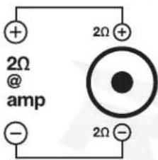
TWO 2Ω SVC WOOFERS = 4Ω LOAD

The minimum impedance for a single dB Series Class D mono amplifier is 2 ohm. Lower impedance loads will cause overheating and may damage the amplifiers.
Do not mix different impedance speakers in series and/or parallel combinations, as unequal power sharing and acoustic outputs will result.
ONE 4Ω SVC WOOFER = 4Ω LOAD

TWO 4Ω SVC WOOFERS = 2Ω LOAD
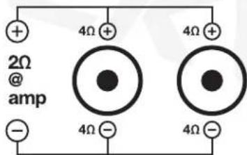
FOUR 4Ω SVC WOOFERS = 4Ω LOAD

FOUR 8Ω SVC WOOFERS = 2Ω LOAD

Woofer Wiring Guide (continued)
DVC Configurations
ONE 2Ω DVC WOOFER = 4Ω LOAD
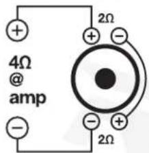
TWO 2Ω DVC WOOFERS = 2Ω LOAD

THREE 2Ω DVC WOOFERS = 3Ω LOAD

ONE 4Ω DVC WOOFER = 2Ω LOAD

TWO 4Ω DVC WOOFERS = 4Ω LOAD

THREE 4Ω DVC WOOFERS = 2.67Ω LOAD

FOUR 2Ω DVC WOOFERS = 4Ω LOAD (parallel/series)

FOUR 4Ω DVC WOOFERS = 2Ω LOAD

Troubleshooting
| PROBLEM | CAUSE/SOLUTION |
| Amp goes into protect mode | 1. Short circuit protection - Caused by the power or ground wire not being fastened tightly.Disconnect the speakers from the amp. If the amp is still in protect mode, you now know the issue is somewhere with the power, ground, or remote wire. You should check and make sure the ground is tight. You should check the power wire terminals. Make sure the positive is going to the positive, and the negative is going to the negative. If all this is secure, you can use a multimeter and make sure you are getting 12 – 14.4 volts coming from your power wire. If this is all checking out properly, then you should check that the remote wire is properly connected to the remote wire on your receiver. Many times people mistakenly connect it to the antenna wire instead. If this is correct, you should also use a multimeter and make sure your remote wire is getting 5 volts.2. Thermal protection - This happens when the amplifier overheats. Check that your subwoofers and other speakers are compatible with your amp and that they are wired correctly.3. Blown speaker - To check for a blown speaker, disconnect all the speakers from the amplifier. If the amp goes out of protect mode, then the problem is indeed a blown speaker. Find which speaker is blown and replace it.4. Wrong speaker impedance - Replace the speaker(s) with one of the proper impedance.5. Speaker wires touching - If the positive and negative speaker wires that run from your speakers to your amplifier touch each other either by the speaker terminals or by the amplifier terminals, the amp will go into protect mode. Check all speaker connections to ensure that the wires are not touching.6. Reverse polarity protection - Reverse polarity means the positive and negative power wires are backward. Connect the speaker wires to the correct terminals.7. Power wire gauge - If your power and ground wire are not thick enough, the amp will go into protect mode to protect itself from unsafe signals. Be sure to use the proper gauge wires.8. RCA cables - RCA patch cables that are grounded out or otherwise faulty can also cause the protect light to come on. To check this, you can simply hook up a set of known good RCA cables to your head unit and amp. If that causes the light to turn off, replacing the RCA cables will fix the problem. |
| Amp won't power on | 1. The external fuse is not properly secured to the power wire or is not making proper contact to the wire.Ensure the fuse is properly seated and making contact.2. Your external fuse (inside the fuse holder) is blown. Replace the fuse. Never replace the supplied external fuse with one of a larger value.3. Check the ground wire. Make sure the connection is 100% secure and tight.4. Power wire is not connected properly to the ring terminal or it has acid corrosion on it. Check the connection to the ring terminal and use a wire brush to clean any corrosion off the ring.5. Check the power wire. Make sure the positive is wired to the positive, and the negative is going to the negative. Make sure the power wire is secure.6. Check the remote turn-on wire. Make sure that this wire is connected securely to the amplifier on one end, and make sure the other end is connected to the remote turn-on of the receiver. A common error we see is the remote turn-on gets connected to the antenna wire instead of the remote turn-on wire of the head unit. Please note the remote turn-on wire is a required wire. The amp will not work if this is not connected.It is also possible the remote terminal is loose and fell out.7. Power wire is connected to the ground terminal of the amplifier. Connect the power wire to the +12V terminal of the amp.8. Power or ground wire became loose. Check all connections and make sure they are tight. |
| Power but no sound | 1. Check if any protection lights are on. If protection lights are on, please refer to the “Power and Protection Circuitry” section on page 12 and the “Amp goes into protect mode” section on page 17.2. Make sure the RCA cable that is plugged into your amplifier is plugged into the RCA input. If you have it plugged into the RCA output, then the amplifier will not get any sound.3. Check the RCA cable that is going from the amplifier to the receiver. We recommend having a spare RCA cable to test with. Many times RCA cables go bad since they are thin cables. You can also test your |
| Power but no sound | RCA signal using a multimeter.4. The next thing to check is the speaker wire that is going from the amp to the speakers. If the amplifier is in bridged mode, then be sure you connected the speaker wire to the proper terminals.5. Check your gain – on the amp and/or on your bass remote. If it is on 0, then turn it up slowly.6. Check the RCA cable that is plugged into your receiver. Make sure you plugged the amplifier into the pre-amp output that is red and white. In many cases we have seen customers plug the RCA into the RCA video of their receiver, which is yellow. If this is the case, just plug the RCA into the proper connections and your problem will be solved.7. There is a setting on your receiver that can disable your RCA outputs. The setting is under fader/balance control. On your receiver navigate to fader/balance and find the setting, then make sure you enable front, rear, and sub preamp outputs. Sometimes the head unit will allow you only to enable front and rear, which would cause the amp to have no sound.8. Speaker wire is not making a good contact on the speaker output of the amp or on the speaker terminal. You need to make sure the speaker wire is securely tightened into the speaker terminal and the amplifier terminal.9. A pinched or cut speaker wire that is now not running a signal. Speaker wire is very thin and can rip or tear easily. If you have spare speaker wire, then you can test this issue with new speaker wire and see if that solves your issue. You can also visually inspect your current speaker wire.10. Make sure the positive and negative speaker wire are running to the positive and negative speaker terminal of the amp. If they are reversed, then the speaker will play no sound or very little sound. |
| Amp is clipping | 1. Speakers/subs are too powerful for the amplifier you are using. Check the compatibility of your speakers/subs. Replace incompatible speakers/subs with compatible ones.2. If the speakers/subs are wired at a lower impedance (ohms) than the amp is supposed to be playing, this can cause the amp to clip. Wire the speakers/subs at the proper impedance. |
| Amp is clipping | 3. If the gain setting is too high, this can cause the amp to clip. The proper way to set your gain is to turn your receiver volume to 75% of the max, and then slowly turn your gain up. The second you hear any slight distortion, turn it down one notch and leave it at that setting. Amps are not meant to be played with the gain up to the max. If this is the case, lower your gain slowly until you hear the amplifier stop clipping.4. A poor ground cable connection can cause your amp to clip because improper power is getting to the amp. Check your ground connection and make sure that the cable is securely tightened.5. A very common cause of amplifier clipping is power and ground wire that is too thin of a gauge size for the amplifier. Determine the proper wire gauge necessary and replace existing wires.6. If using multiple devices that all have a volume control (such as an equalizer or processor, receiver, and the amp), then you would need to lower one or two of those devices to stop the amp from clipping. |
| Distortion, background noise, crackling, or hissing in the speakers | 1. First check to see how your wires are run. If your RCA cables and speaker wire are run alongside your power cables, they will pick up feedback. If this is the case, you will need to run the RCA cable on the other side separate from your power cable.2. A poor ground cable connection can cause your amp to clip because improper power is getting to the amp. Check your ground connection and make sure that the cable is securely tightened.3. Engine noise – you will know it is engine noise if every time you rev your engine the noise gets louder. You can install a ground loop isolator on the receiver's power lead to cut down on signal pollution. Most often, however, engine noise comes from a loose or intermittent ground connection. Make sure your ground connection is tight and that you are using the proper gauge cable.4. If your gain on your amp is set to the max and your receiver has a high preamp voltage, it will cause some unwanted noise. To properly set your gain, play a CD or other music. Now put the receiver volume to 75% – 80% of the max. Then slowly turn the gain of the amp to a setting where you do not hear a loud hiss. A low hiss is acceptable, as with music playing you will never hear it. Please note the amp gain is not a volume control. It is meant to be matched to the preamp voltage of a head unit. It is important to properly set your gain when you buy a new amp. |
| Distortion, background noise, crackling, or hissing in the speakers | 5. Noise can be picked up due to bad RCA cables. Specially the super cheap ones. We recommend doing a test with different RCA cables. Replace the RCA cables if needed.6. Low-quality speaker wires will also cause noise. We recommend you buy high-quality insulated speaker wire made for vehicle applications. |
| Sound is too low | 1. This can be caused by wiring at too high of an impedance (ohms) and the amp puts out low power, at 4 or 8 ohms for example. To resolve this, you will have to properly wire your speakers/subs to the amplifier.2. Check the gain level on the amp. You may need to turn it up.3. Power and ground wire that are too thin of a gauge size for the amplifier may cause low sound. Determine the proper wire gauge necessary and replace existing wires.4. Make sure your positive and negative speaker wires are not reversed, as this would cause the sub to move but not make much noise.5. Check your Subsonic HPF control setting on your amplifier. You may need to filter out more high frequencies, which your sub is not meant to play. Try lowering the frequency of that LPF control and see if that helps.6. On your receiver it is very common to have a volume level control for the preamp outputs (separate from your master volume control). To fix this, you can navigate to the audio settings, and search for subwoofer level controls, as well as front and rear preamp output controls. Crank up the level on this setting and you will be back in business.7. Amplifier may not be powerful enough. If this is the case, we recommend upgrading to a more powerful amplifier. |
| Amp keeps blowing fuses | Main Fuse - If you determine that your main fuse is blowing, then you'll want to pay attention to when it blows. Try inserting a good, properly rated fuse with your head unit—and amplifier—turned off. If the fuse blows immediately, when everything is off, then you're probably dealing with some kind of short in the power cable between the main fuse and the distribution block, or between the main fuse and the amplifier if there is no distribution block in the system. |
| Amp keeps blowing fuses | Distribution Block Amp Fuse - If both sides of the main fuse have power, and one side of the distribution block has power, but the other side of that fuse is dead, then you're either dealing with a shorted power wire or an internal amplifier fault. There are a few ways to determine which one is the culprit, depending on how your amp is installed and where the wires are routed.1. Check if you can see power wire that connects the distribution block to your amp. In an ideal situation, you'll be able to see the entire length of the wire. If that isn't possible, then the next best thing is to just disconnect the power wire from your amp, make sure that the loose end isn't in contact with ground, and check whether the fuse still blows. If it does, then the problem is in the power wire, and replacing it will almost certainly fix your problem. Of course, you'll have to take vehiclee when routing the new wire so that it doesn't end up shorting out as well. If the fuse doesn't blow with the power wire disconnected from your amp, then you have an internal amplifier problem.Internal Amplifier Fuse - If the fuse blows when the amp is turned up, then you likely have subwoofers that are either incompatible or that are wired at too low of an impedance. Rewire to achieve proper impedance, or replace the subwoofers with compatible ones. Check and make sure the power and ground wires did not get crossed. Also, check and make sure your speaker wires are not crossed. |
| Amp gets very hot | The main reason amps overheat is if the impedance they are running at is very low, or if the subwoofer requires more power than the amp can give it. Also if the wiring cannot give the proper current fast enough, it can cause the amp to get hot as well. Make sure the amp is running at the proper impedance, or use subwoofers that are compatible with the amp. Make sure the wiring is correct and you are using the proper wires for your system.A poor ground cable connection can cause your amp to get very hot. Check your ground connection and make sure that the cable is securely tightened.Check the location where your amp is mounted. Make sure it is in a spot where it will receive proper ventilation. |
| Amp or powered sub does not turn off when you turn off the vehicle | 1. This situation happens when you connect the remote turn-on wire to a constant 12V power wire (often this is a yellow wire) instead of to the remote turn-on wire of your receiver's wire harness. Pull out your receiver and plug the amplifier's remote turn-on wire into the proper remote turn-on terminal of your receiver's wire harness.2. In a rare situation, the remote turn-on wire input is touching the power wire, which can also cause this same issue. If this is what is happening, then simply take the remote turn-on wire out of the amplifier terminal and vehiclefully put it back in so that it is not touching the power wire. |
| One channel on the amp isn't working | 1. Check the RCA cable that is going from the amplifier to the receiver. We recommend having a spare RCA cable to test with. Many times RCA cables go bad since they are thin cables. You can also test your RCA signal using a multimeter.2. Check the RCA cable that is plugged into your receiver. Make sure you plugged the amplifier into the pre-amp output that is red and white. In many cases we have seen customers plug the RCA into the RCA video of their receiver, which is yellow. If this is the case, just plug the RCA into the proper connections and your problem will be solved.3. There is a setting on your receiver that can disable your RCA outputs. The setting is under fader/balance control. On your receiver navigate to fader/balance and find the setting, then make sure you enable front, rear, and sub preamp outputs. Sometimes the head unit will allow you only to enable front and rear, which would cause the amp to have no sound.4. Speaker wire is not making a good contact on the speaker output of the amp or on the speaker terminal. You need to make sure the speaker wire is securely tightened into the speaker terminal and the amplifier terminal.5. Make sure the positive speaker wire is connected to the positive terminal on the speaker and on the amp, and make sure the negative is connected to the negative.6. Make sure the gain of the amplifier is turned up. |

ROCKVILLE
©2024 ROCKVILLE // Features and specifications are subject to change and/or improvement without notice.
- ROCKVILLE
- DB SERIES
- CLASS D MONO 2-OHM AMPLIFIERS
- OWNER'S MANUAL
- ATTENTION: WATCH THIS VIDEO BEFORE FIRST USE
- WHO READS MANUALS
- INTRODUCTION
- IMPORTANT SAFETY INSTRUCTIONS
- INSTALLATION
- INSTALLATION BASICS
- MOUNTING THE AMPLIFIER
- WIRING
- ATTENTION
- SETTINGS
- ADJUSTING THE SYSTEM
- AUDIO PREAMP INPUT
- USING THE BUILT-IN LOW PASS ELECTRONIC CROSSOVER
- USING THE SUBSONIC HIGH PASS FILTER
- USING THE PHASE SHIFT
- SEALED ENCLOSURES
- PORTED ENCLOSURES
- EXAMPLE
- INPUT CONFIGURATIONS
- OUTPUT CONFIGURATIONS
- TWIN AMP BRIDGING (DB14, DB15, DB16 ONLY)
- FEATURES
- BASS EQUALIZATION CIRCUITRY
- AUDIO OUTPUT SECTION
- POWER AND PROTECTION CIRCUITRY
- MUTE CIRCUIT
- BASS REMOTE
- BATTERY VOLTAGE
- ADDITIONAL FEATURES
- SPECIFICATIONS
- DB12
- DB13
- DB14
- SPECIFICATIONS (CONTINUED)
- DB15
- DB16
- WOOFER WIRING GUIDE (CONTINUED)
Marque : Rockville
Modèle : dB14
Catégorie : Recepteur