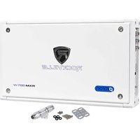
RXM8BTW - Recepteur Rockville - Notice d'utilisation et mode d'emploi gratuit
Retrouvez gratuitement la notice de l'appareil RXM8BTW Rockville au format PDF.


| Type de produit | Récepteur Bluetooth stéréo |
| Marque | Rockville |
| Modèle | RXM8BTW |
| Dimensions (L x H x P) | 430 x 50 x 250 mm |
| Poids | 2,5 kg |
| Alimentation | 230 V ~ 50 Hz |
| Consommation électrique | 30 W |
| Connectivité sans fil | Bluetooth 5.0 |
| Portée Bluetooth | 10 mètres |
| Entrées audio | USB, SD, Auxiliaire 3,5 mm, RCA |
| Sortie audio | Haut-parleurs (2 x 50 W), Casque |
| Radio FM | Oui, avec recherche automatique |
| Lecture USB/SD | MP3, WMA, WAV |
| Entretien et nettoyage | Chiffon doux et sec, éviter les produits abrasifs |
| Consignes de sécurité | Ne pas exposer à l'humidité, ne pas obstruer les fentes de ventilation |
| Pièces détachées | Non fournies, contacter le service après-vente |
| Réparabilité | Faire appel à un professionnel agréé |
FOIRE AUX QUESTIONS - RXM8BTW Rockville
Questions des utilisateurs sur RXM8BTW Rockville
0 question sur cet appareil. Repondez a celles que vous connaissez ou posez la votre.
Poser une nouvelle question sur cet appareil
Téléchargez la notice de votre Recepteur au format PDF gratuitement ! Retrouvez votre notice RXM8BTW - Rockville et reprennez votre appareil électronique en main. Sur cette page sont publiés tous les documents nécessaires à l'utilisation de votre appareil RXM8BTW de la marque Rockville.
MODE D'EMPLOI RXM8BTW Rockville
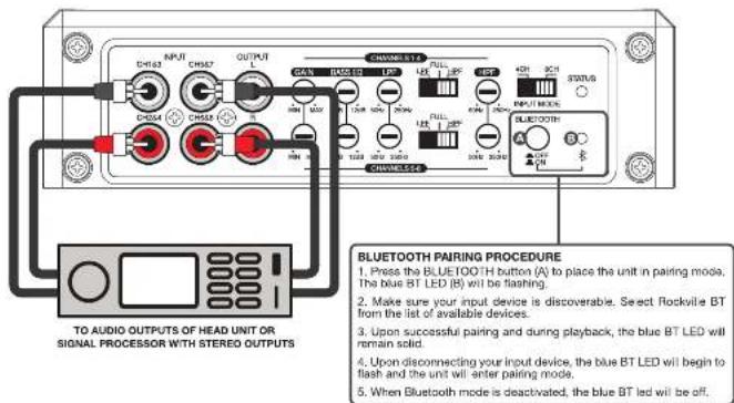
INPUT
4
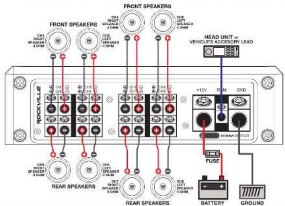
SPEAKER CONFIGURATIONS
5
FEATURES / SPECIFICATIONS
6
- Bluetooth Wireless Capability with Auto Pairing
- Compact Design and High Power
• High-Speed MOSFET Power Supply
• Studio-Grade Bipolar Output Stage Transistors
• Micro Size Architecture with SVD Component Circuitry
• TI Digital Class D Audio Topology - 4-Way System Protection Circuitry (DC, Short, Thermal, Overload)
- Auto Thermal Control Circuit
• OEM Integration Smart Turn On Circuit - Mute and Delay Turn-On Circuit
• Power and Diagnostic LED Status indicator
• Salt Water Resistant High Gloss Aluminum Casing
• UV and Salt Water Resistant Paint, Silk Screen and Heat Sink Enclosure
- RMS Power Output @ 4 Ohms: 65 Watts x 8 Channels CEA Rated - RMS Power Output @ 2 Ohms: 95 Watts x 8 Channels
• RMS Bridged Power Output @ 4 Ohms: 190 Watts x 4 Channels
• Peak Bridged Power Output @ 4 Ohms: 380 Watts x 4 Channels
• 750 Watts RMS System Power
• 1500 Watts Peak System Power
• Minimum Speaker Impedance: 2 Ohm - 4 Ohm
• Minimum THD at Rated Power: < 0.05%
• Marine-Grade Conformal Coated Boards Resist
Corrosion from Salt Spray and Moisture
• Stainless Steel Bolt Down Molded Terminals
• Stainless Steel RCA Level Inputs
- Conforms to the American Boat and Yacht Council (ABYC) Marine Electronic Standards
- Configurable to 8-6-4 Channels or 4.2 System
• 4 CH / 6 CH Input Mode Selector
• Independent Crossover Controls between CH1-4 and CH5-8
- Selectable Bass
• Bass Equalization: Fully Adjustable 0 - 12dB @ 45Hz
• Full Range / Low Pass / High Pass Configurable
• Variable High-Pass Filter: 50Hz - 250Hz @ 12dB/per Octave
• Variable Low-Pass Filter: 50Hz - 250Hz @ 12dB/per Octava
- RCA Line Output
• Frequency Response: 10Hz 40KHz
- S/N Ratio: > 100dB
• Damping Factor: > 200 @ 100Hz
- Input Voltage: 150mV - 6V
• Input Impedance: 22K
• Channel Separation: >60dB
- Fuse: 80A x 1
• Dimensions: (W x H x L) 6.7 x 2 x 11.5

ROCKVILLE
RockvilleAudio.com
06103 ROCK/UL E) The information presented is subject to change and/or improvement without action
ROCKVILLE
RXM8BT 8-CHANNEL 1500W MARINE/BOAT AMPLIFIER w/BLUETOOTH OWNER'S MANUAL
ATTENTION: WATCH THIS VIDEO BEFORE FIRST USE!
Who reads manuals?
Scan the QR codes or go to URLs to access how-to video(s), the owner's manual, and other important information you may need to get the most out of your item.
If you prefer written instructions, please read ahead! With Rockville you get many options.

rockvillesupport.com/rxm8btb

rockvilesupport.com/rxm8btw
Missing Items? If you ordered a bundle that includes more than one product and you are missing part of your bundle, then it just means your order shipped from two different warehouses. You will receive the remaining items very soon. If you have any concerns or inquiries, feel free to call our customer support center at 1-646-758-0144. Monday through Thursday, 24 hours a day/7 days a week.
WIRING INSTRUCTIONS
POWER CONNECTION: The amplifier power terminal leased -12V must be connected directly to the positive terminal of the vehicle's battery. Connecting the +12V cable to any other point, such as the fuse book, will reduce power output and cause noise & distortion (refer to the diagrams on page 5). We suggest you construct a Red wiring harness with 2 additional fuses. One fuse should be located near the car battery. This fuse offers protection against damage from short circuits to the car chassis between the battery and the amplifier. A second fuse closer to the amplifier offers additional safety to the amplifier itself. This fused red power wire should be attached to the amplifier power terminal. The fuse is connected to the same connection of at least 8 gauge. The harness should terminate in a large ring terminal for connection directly to the positive terminal of the car battery.
GROUND: A second black color wire of equal gauge should be used as a ground connection to a welded chassis member (refer to the diagrams on page 5). When connecting the ground wire make sure that there is no paint or other insulator blocking a good ground connection. Fasten the cable end with a ring terminal using a screw. Attach the black ground wire to the amplifier screw terminal marked GND. Ensure that the ground connection is as short as possible. When installing multiple amplifiers, mount them in close proximity so that they can all share the same ground point.
REMOTE TURN-ON: The remote turn-on connection is located in between the power and ground connections. This connection is responsible for turning the amplifier on and off with the rest of the system. 12 gauge wire can be used to make this connection to your radio's power antenna lead (refer to the diagrams on page 5). Should your system not have any turn on leads, you can wire the remote terminal to an accessory lead or radio terminal in the vehicle's fuse block which turns on with your car's ignition. This connection type will turn the amplifier on or off with the ignition, independent of whether the radio is on or off.
SPEAKER CONNECTIONS: Depending on the type and number of speakers used with the amplifier, wire them to the speaker terminals as per the wiring diagram. For most applications 16 gauge speaker wire (put no thinner than 20 gauge) should be used. For runs in excess of 10 feet, 16 gauge speaker wire is recommended. When wiring the speakers, pay special attention to the polarity of the speaker terminals. Make sure they match the polarity of the corresponding amplifier speaker terminal. Do not ground any speaker leads to the chassis of the vehicle. Refer to the diagrams on page 4).
INTRODUCTION
1
Thank you for purchasing this Rockville RXM8BT amplifier. Please read this owner's manual carefully for proper use of your amp. Should you need assistance, please call our technical help ine at 1-646-758-0144, 24 hours a day/7 days a week.
PRECAUTIONS
This unit is for negative ground 12V DC operation only. Use speakers with an impedance of 2 or 4 ohms (4 to 8 ohms when used as a bridging amplifier). Avoid installing the unit where:
- It would be subject to high temperatures, such as from direct sunlight or hot air from the heater.
- It would be exposed to rain or moisture.
- It would be subject to dust or dirt.
If your car is parked in direct sunlight and there is a considerable rise in temperature inside the car, allow the unit to cool off before operation. When installing the unit horizontally, be sure not to cover the heatsink vents. If this unit is placed too close to the vehicle's radio, interference may occur. In this case, separate the amplifier from the radio. This amplifier employs a protection circuit to protect the transistors and speakers if the amplifier malfunctions. Do not attempt to test the protection circuits by covering the heatsink or connecting improper loads. Doing so may cause irreparable damage to the amplifier.
INSTALLATION
Mount the amplifier in the trunk or hatch area of your vehicle. Never install an amplifier in the engine compartment or on the firewall. Please be sure to leave breathing room around the amplifier heat sink so that it can dissipate the heat it produces efficiently. When mounting the amplifier on the trunk floor, be sure to watch for your gas tank, gas lines and electrical lines. Do not drill or mount any screws where they might penetrate the gas tank of your car.
TROUBLESHOOTING
3
NO FUNCTION
- Make sure all connections are properly seated and secure fastened.
- Fuse may be blown. Replace fuse with one of the same value and of the same type. Never use any other value / type fuse. Amplifier uses an 80 amp fuse.
NO SOUND:
- Check speaker connections and ensure that they are connected correctly.
NO SOUND / RED PROTECTION LED IS ON:
• The negative and positive speaker wires maybe touching thus causing a short circuit. Find the point of contact and separate the wires.
- If you use a 2 ohm speaker in stereo mode, a 4 ohm speaker in bridge mode or tri-mode and tel set is overloaded, turn the gain control to MIN until operation returns to normal.
POOR SOUND QUALITY (DISTORTION):
- The speakers are overloaded. Turn down the volume on your radio and check the gain levels on teh amplifier.
NO STEREO SOUND / WEAK BASS:
- Speaker cables may be hooked up backwards. Please double check all speaker connections.
Marque : Rockville
Modèle : RXM8BTW
Catégorie : Recepteur