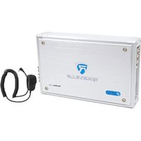
RXM-S20 - Recepteur Rockville - Notice d'utilisation et mode d'emploi gratuit
Retrouvez gratuitement la notice de l'appareil RXM-S20 Rockville au format PDF.


| Type de produit | Récepteur audio marin / autoradio |
| Marque | Rockville |
| Modèle | RXM-S20 |
| Dimensions (L x H x P) | 178 x 50 x 160 mm (standard DIN) |
| Poids | 0,9 kg |
| Alimentation | 12V DC (batterie véhicule) |
| Puissance de sortie | 4 x 50 W (max) |
| Tuner FM/AM | Oui, avec mémorisation de stations |
| Entrées audio | USB, AUX 3,5 mm, Bluetooth |
| Sorties audio | 4 canaux haut-parleurs + sortie préamplifiée subwoofer |
| Formats compatibles | MP3, WMA, WAV |
| Fonctions principales | Lecture USB, streaming Bluetooth, radio FM/AM, téléphone mains-libres |
| Matériau du panneau avant | Plastique ABS avec finition métallisée |
| Étanchéité | Conçu pour usage marin (résistant aux éclaboussures) |
| Écran | LCD rétroéclairé avec affichage des informations |
| Contrôle | Boutons physiques et télécommande incluse |
| Entretien et nettoyage | Essuyer avec un chiffon doux et sec. Éviter les solvants. |
| Sécurité | Fusible de protection intégré (10A) |
| Pièces détachées et réparabilité | Disponibles via service après-vente Rockville |
| Informations générales | Garantie 1 an. Fabriqué en Chine. |
FOIRE AUX QUESTIONS - RXM-S20 Rockville
Questions des utilisateurs sur RXM-S20 Rockville
0 question sur cet appareil. Repondez a celles que vous connaissez ou posez la votre.
Poser une nouvelle question sur cet appareil
Téléchargez la notice de votre Recepteur au format PDF gratuitement ! Retrouvez votre notice RXM-S20 - Rockville et reprennez votre appareil électronique en main. Sur cette page sont publiés tous les documents nécessaires à l'utilisation de votre appareil RXM-S20 de la marque Rockville.
MODE D'EMPLOI RXM-S20 Rockville
65-C1294-MAC 210*140mm 105g铜版纸 CE7438
ROCKVILLE



INTRODUCTION
Thank you for purchasing this Rockville RX Proton Series amplifier. Before installing please read this instruction manual carefully. This amplifier has been designed to provide high quality performance and its performance will only be as good as the care and quality of components with which it is installed. We therefore advise that you read these instructions very carefully to familiarize yourself with the product and it's features. The instructions for mounting and connecting the set have to be followed precisely. If necessary, a service center should be consulted. All connections for DC power, signal input and speaker outputs can be carried out easily and safely by way of RCA and screwed terminals.
INSTALLATION INSTRUCTIONS
Before you begin your installation, disconnect the NEGATIVE(-) terminal from your car's/boat's battery. This safety precaution will avoid possible short circuits while wiring your amplifier. Rockville amplifiers operate on 12-volt negative ground systems only. It is recommended that you layout your sound system design on paper first. This will help you during the installation so that you will have a wiring flow chart and not miss-wire any of your components. Never install an amplifier in the engine compartment or on the firewall. Please be sure to leave breathing room around the amplifier heat sink so that it can dissipate the heat it produces efficiently. The amplifier can be installed either horizontally or vertically. When mounting the amplifier on the trunk floor, be sure to watch for your gas tank, gas lines and electrical lines. Do not drill or mount any screws where they might penetrate the gas tank of your vehicle.
PRECAUTIONS
This unit is designed for negative ground 12V DC operation only. Use speakers with an impedance of 2 or 4 Ohms (4 to 8 Ohm when used as bridging amplifier) Avoid installing the unit where:
- It would be subject to high temperatures, such as from direct sunlight or hot air from the heater.
- It would be subject to dust or dirt.
If your car is parked in direct sunlight and there is a considerable rise in temperature inside the car, allow the unit to cool off before operation. When installing the unit horizontally, be sure not to cover the heatsink fins with the floor carpet. If this unit is placed too close to the car radio, interference may occur. In this case, separate the amplifier from the car radio. This power amplifier employs a protection circuit to protect the transistors and speakers if the amplifier malfunctions. Do not attempt to test the protection circuits by covering the heatsink or connecting improper loads.
WIRING INSTRUCTIONS
POWER CONNECTION
The battery terminal (BATT) must be connected directly to the positive terminal of the vehicle battery to provide adequate voltage and minimize noise. Connecting the battery terminal lead to any other point (such as the fuse block) will reduce the power output and may cause noise and distortion. Use only 12 gauge or thicker wire for this lead and connect it to the terminal of the battery after all other wiring is completed.
GROUND CONNECTION
The ground terminal (GND) connection is also critical to the correct operation of the amplifier. Use a wire of the same gauge as the power connection and connect it between the ground terminal (GND) of the amplifier and a metal part of the vehicle close to the mounting location. This wire should be as short as possible and any paint or rust at the grounding point should be scraped away to provide a clean metal surface to which the end of the ground wire can be screwed or bolted.
REMOTE TURN-ON CONNECTION
The amplifier is turned on by applying +12V to the remote turn-on terminal (REM). The wire lead to this terminal should be connected to the "Auto-Antenna" lead from the car stereo which will provide the +12V only when the car stereo is turned on. If the car stereo does not provide an "Auto-Antenna" lead, the remote turn-on lead may be wired to an "Accessory" or "Radio" terminal in the car's fuse block. This will turn the amplifier on and off with the ignition key, regardless of whether the car stereo is on or off. The remote turn-on lead does not carry large currents. So 20 gauge wire may be used for this application.
SPEAKER CONNECTIONS
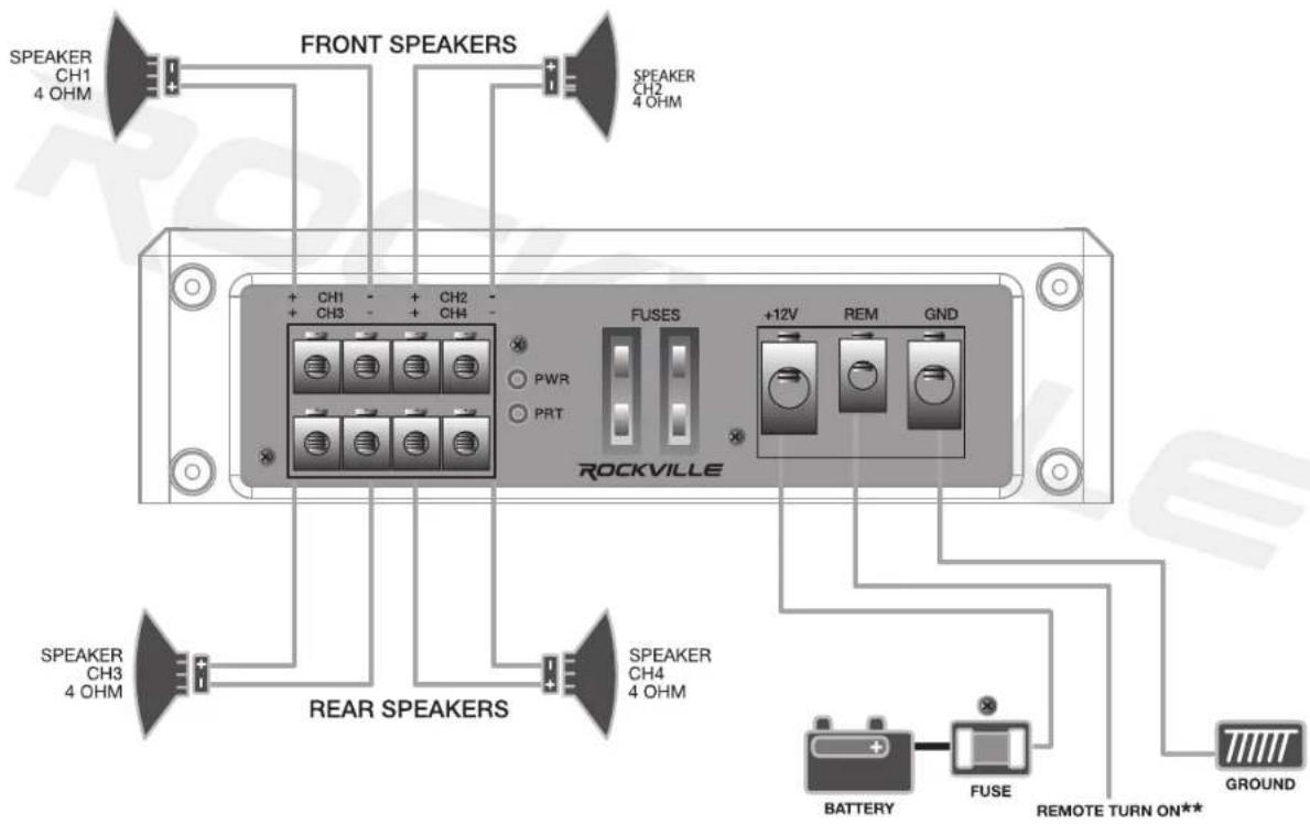
Depending on the type and number of speakers used with the amplifier, wire them to the speaker terminals as per the appropriate wiring diagram. For most applications 18 gauge wire should be used for the speaker leads but never thinner than 20 gauge. For leads in excess of 10 feet, 16 gauge is recommended. When wiring the speakers, pay careful attention to the polarity of the terminals on the speakers and make certain they correspond to the polarity of the corresponding terminals on the amplifier. Do not ground any speaker leads to the chassis of the vehicle.
OPERATION
GND(-) = GROUND CONNECTION
A black color wire of at least 4 gauge should be used as a ground connection to a welded chassis member. When connecting the ground wire make sure that there is no paint or other insulator blocking a good ground connection. When installing multiple amplifiers, mount them in close proximity so that they can all share the same ground point. Route ground cables from the radio and all other equipment (equalizer, active crossovers, etc) to the same ground point. Attach the black ground wire to the amplifier screw terminal marked GND. Be sure to keep ground and power cables as short as possible.
+12V = POWER SUPPLY
We suggest you construct a red wiring harness with 2 additional fuses. One fuse should be located near the car battery. This fuse near the battery offers protection against damage from short circuits to the car chassis between the battery and the amplifier. A second fuse closer to the amplifier offers additional safety to the amplifier itself. This fused red power wire should be attached to the amplifier power terminal marked +12V. The harness should terminate in a large ring terminal for connection directly to the positive terminal of the car battery.
REM(ON/OFF) REMOTE CONTROL
Connect the REM terminal to the automatic antenna connector of your car radio. Now when turning on and off your car radio, the amplifier automatically switches ON and OFF.
TROUBLESHOOTING
No Function:
Check that all cables and wires are properly connected (+12V, GND, REM, speaker terminals, RCA inputs/outputs). Check the fuse. Never replace the built in or supplied external fuse with one of a larger value.
No Sound:
Check that all speaker cables are connected correctly (at amp and at speakers).
No Sound / Red LED Protection Shines:
Turn off your system, disconnect one speaker at a time and try to determine which speaker might be faulty. Correct the condition and restart the amplifier. If you use a 2 Ohm speaekr in stereo mode, a 4 Ohm speaekr in bridged mode or tri-mode and the amp is overloaded, turn the gain contori to MIN until operation returns to normal.
Poor Sound Quality (Distortions) / No Stereo Sound And A Weak Bass:
The speakers are overloaded, turn down the volume level and check the volume control positions. Speaker cables (+) and (-) are mixed up, unit wired out of phase.
INPUT WIRING DIAGRAM

INPUT WIRING DIAGRAM
PUBLIC ADDRESS FUNCTION
The RXM-S20 and RXM-S30 feature a marine pubic address system with microphone* Simply plug the microphone in to the 3.5mm jack and you are ready to go. The amplifier features talk-over functionality. When microphone is keyed music will fade to the background. When microphone is unkeyed, music slowly fades back in. If you key the mic and there is no sound, be sure to check the volume knob on the mic.
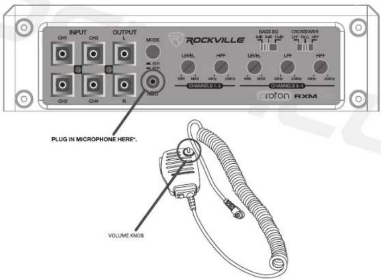
*Microphone included.
INPUT WIRING DIAGRAM
4 CHANNEL AMP WITH 2 CHANNEL INPUT
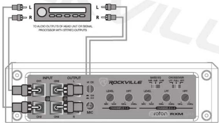
If your head unit has one pair of Left and Right RCA out put jacks, plug them in to RCA input Jacks 1 and 2 of the amplifier and set the input model switch to the 2CH position.
The amplifier preamp circuit will automatically mix the signals to channels 3 and 4 thereby preserving your Left and Right Balance control but with no Fade control Front to Rear.

INPUT WIRING DIAGRAM
4 CHANNEL AMP WITH 4 CHANNEL INPUT
If your head unit has 2 pairs of RCA output jacks, input Front Left and Front Right in to Channels 1 and 2. Then attach radio output Rear Left and Rear Right to Channels 3 and 4. Set the input Mode Switch to 4CH position. The pre amp circuitry will not mix any signals thereby preserving full Left to Right Balance and Front to Rear fader control.
Should your head unit have an additional subwoofer RCA output, that typically needs to be attached to a separate subwoofer amplifier.
When configuring a 4 channel amplifier to a 3 channel system, you can use an RCA Y adaptor to send the subwoofer proamp signal to channels 3 and 4 and bridge those channels to the subwoofer. Use Y adaptors to mix channels 1 and 3 and input them in to RCA Channel 1, then mix channels 2 and 4 and input the min to RCA Channel 2. The result will be preserved Left and Right balance with constant subwoofer output.
SPEAKERS CONNECTIONS
SPECIFICATIONS
RXD-F20
• CEA/RMS Power Ratings:
300 Watts (4 x 75 Watts)/600 Watts (4 x 150 Watts RMS) @ 4 Ohms
400 Watts (4 x 100 Watts)/800 Watts (4 x 200 Watts RMS) @ 2 Ohms
400 Watts (2 x 200 Watts)/800 Watts (2 x 400 Watts RMS) @ 4 Ohms Bridged
• Peak Power: 1600Watts (2 x 800 @ 4 Ohms)
• Frequency Response: 15Hz - 20KHz
• Sensitivity: 100dB @ 1w/1m
• Damping Factor: > 200 @ 100Hz
- Dual 25 Amp Fuses
• Dimensions:(W x H x L)6.7" x 1.98" x 10.7"
• High-Speed MOSFET Power Supply
• Studio-Grade Bipolar Output Stage Transistors
- Fully Adjustable 12dB / Octave Crossover with Differential Circuitry
• CH1 & CH2 High Pass 50Hz - 250Hz
• CH3 & CH4 Low pass 50Hz - 250Hz
- CH3 & CH4 High Pass 50Hz -250Hz
• 2 Ohm Stable Stereo
• 4 Ohm Mono Bridgeable
• 3 Channel Mixed-Mono Capable
- Selectable +6dB/+12dB Bass Equalizer
- Mute and Delay Soft Start System
• Double Sided Surface Mount (SMD) PCB Design
• Full IC-Controlled Protection Circuitry
• 2 CH / 4 CH input Mode Switch
• RCA Preamp Line Output
• 8 Volt Preamp Circuitry
• Status Mode LED Indicator
• 4 Gauge Lucite Encapsulated Power/Ground Terminals
• 12 Gauge Lucite Encapsulated Speaker Terminals

RXD-F30
• CEA/RMS Power Ratings:
400 Watts (4 x 90 Watts)/800 Watts (4 x 200 Watts RMS) @ 4 Ohms
600 Watts (4 x 150 Watts)/1200 Watts (4 x 300 Watts RMS) @ 2 Ohms
600 Watts (2 x 300 Watts)/1200 Watts (2 x 600 Watts RMS) @ 4 Ohms Bridged
- Peak Power: 2400Watts (2 x 1200 @ 4 Ohms)
• Frequency Response: 15Hz - 20KHz
• Sensitivity: 100dB @ 1w/1m
• Damping Factor: > 200 @ 100Hz
- Dual 30 Amp Fuses
- Dimensions:(W x H x L)6.7" x 1.98" x 12.28"
- High-Speed MOSFET Power Supply
• Studio-Grade Bipolar Output Stage Transistors
- Fully Adjustable 12dB / Octave Crossover with Differential Circuitry
• CH1 & CH2 High Pass 50Hz - 250Hz
• CH3 & CH4 Low pass 50Hz - 250Hz
- CH3 & CH4 High Pass 50Hz -250Hz
• 2 Ohm Stable Stereo
• 4 Ohm Mono Bridgeable
• 3 Channel Mixed-Mono Capable
- Selectable +6dB/+12dB Bass Equalizer
- Mute and Delay Soft Start System
• Double Sided Surface Mount (SMD) PCB Design
• Full IC-Controlled Protection Circuitry
- 2 CH / 4 CH input Mode Switch
- RCA Preamp Line Output
• 8 Volt Preamp Circuitry
• Status Mode LED Indicator
• 4 Gauge Lucite Encapsulated Power/Ground Terminals
- 12 Gauge Lucite Encapsulated Speaker Terminals

SPECIFICATIONS
RXM-S20
• CEA/RMS Power Ratings:
300 Watts (4 x 75 Watts)/600 Watts (4 x 150 Watts RMS) @ 4 Ohms
400 Watts (4 x 100 Watts)/800 Watts (4 x 200 Watts RMS) @ 2 Ohms
400 Watts (2 x 200 Watts)/800 Watts (2 x 400 Watts RMS) @ 4 Ohms Bridged
• Peak Power: 1600Watts (2 x 800 @ 4 Ohms)
• Frequency Response: 15Hz - 20KHz
- Sensitivity: 100dB @ 1w/1m
• Damping Factor: > 200 @ 100Hz
• Dual 25 Amp Fuses
- Dimensions: (W x H x L) 6.7 × 1.98" x 10.7
• High-Speed MOSFET Power Supply
• Studio-Grade Bipolar Output Stage Transistors
• Fully Adjustable 12dB / Octave Crossover with Differential Circuitry
• CH1 & CH2 High Pass 50Hz - 250Hz
- CH3 & CH4 Low pass 50Hz - 250Hz
• CH3 & CH4 High Pass 50Hz -250Hz
• 2 Ohm Stable Stereo
• 4 Ohm Mono Bridgeable
• 3 Channel Mixed-Mono Capable
- Selectable +6dB/+12dB Bass Equalizer
- Mute and Delay Soft Start System
• Conformal Coated PCB board
• Water Resistant
- Double Sided Surface Mount (SMD) PCB Design
• Full IC-Controlled Protection Circuitry
• Marine Public Address System with Microphone
• 2 CH / 4 CH input Mode Switch
• RCA Preamp Line Output
• 8 Volt Preamp Circuitry
• Status Mode LED Indicator
* 4 Gauge Lucite Encapsulated Power/Ground Terminals
• 12 Gauge Lucite Encapsulated Speaker Terminals

RXM-S30
• CEA/RMS Power Ratings:
400 Watts (4 x 90 Watts)/800 Watts (4 x 200 Watts RMS) @ 4 Ohms
600 Watts (4 x 150 Watts)/1200 Watts (4 x 300 Watts RMS) @ 2 Ohms
600 Watts (2 x 300 Watts)/1200 Watts (2 x 600 Watts RMS) @ 4 Ohms Bridged
• Peak Power: 2400Watts (2 x 1200 @ 4 Ohms)
• Frequency Response: 15Hz - 20KHz
- Sensitivity: 100dB @ 1w/1m
• Damping Factor: > 200 @ 100Hz
- Dual 30 Amp Fuses
- Dimensions: (W x H x L) 6.7" x 1.98" x 12.28"
• High-Speed MOSFET Power Supply
• Studio-Grade Bipolar Output Stage Transistors
• Fully Adjustable 12dB / Octave Crossover with Differential Circuitry
• CH1 & CH2 High Pass 50Hz - 250Hz
- CH3 & CH4 Low pass 50Hz - 250Hz
- CH3 & CH4 High Pass 50Hz -250Hz
- 2 Ohm Stable Stereo
• 4 Ohm Mono Bridgeable
• 3 Channel Mixed-Mono Capable
- Selectable +6dB/+12dB Bass Equalizer
- Mute and Delay Soft Start System
- Conformal Coated PCB board
• Water Resistant
- Double Sided Surface Mount (SMD) PCB Design
• Full IC-Controlled Protection Circuitry
• Marine Public Address System with Microphone
• 2 CH / 4 CH input Mode Switch
• RCA Preamp Line Output
- 8 Volt Preamp Circuitry
- Status Mode LED Indicator
- 4 Gauge Lucite Encapsulated Power/Ground Terminals
- 12 Gauge Lucite Encapsulated Speaker Terminals


ROCKVILLE
Features and specifications subject to change and or improvement without notice.
Though we tried our best to ensure that this manual is free and clear of errors please don't hold us responsible for printing errors.
Copyright 2019
RockvilleAudio.com
- ROCKVILLE
- INTRODUCTION
- INSTALLATION INSTRUCTIONS
- PRECAUTIONS
- WIRING INSTRUCTIONS
- POWER CONNECTION
- GROUND CONNECTION
- REMOTE TURN-ON CONNECTION
- SPEAKER CONNECTIONS
- OPERATION
- GND(-) = GROUND CONNECTION
- 12V = POWER SUPPLY
- REM(ON/OFF) REMOTE CONTROL
- TROUBLESHOOTING
- NO FUNCTION
- NO SOUND
- NO SOUND / RED LED PROTECTION SHINES
- POOR SOUND QUALITY (DISTORTIONS) / NO STEREO SOUND AND A WEAK BASS
- INPUT WIRING DIAGRAM
- PUBLIC ADDRESS FUNCTION
- 4 CHANNEL AMP WITH 2 CHANNEL INPUT
- 4 CHANNEL AMP WITH 4 CHANNEL INPUT
- SPECIFICATIONS
- RXD-F20
- RXD-F30
- RXM-S20
- RXM-S30
Marque : Rockville
Modèle : RXM-S20
Catégorie : Recepteur