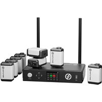
Wireless Tally System - Interphone Hollyland - Notice d'utilisation et mode d'emploi gratuit
Retrouvez gratuitement la notice de l'appareil Wireless Tally System Hollyland au format PDF.


| Type de produit | Système de signalisation sans fil (Tally Light) |
| Marque | Hollyland |
| Modèle | Wireless Tally System |
| Catégorie | Interphone / Signalisation studio |
| Alimentation | Batterie rechargeable lithium-ion (via USB-C) |
| Transmission | Sans fil, radiofréquence 2.4 GHz |
| Portée | Jusqu'à 100 mètres en champ libre |
| Fonctions principales | Signalisation visuelle (LED rouge/verte), sonnerie intégrée, appairage multiple |
| Entretien et nettoyage | Nettoyer avec un chiffon doux et sec, éviter les liquides |
| Sécurité | Utiliser uniquement avec l'adaptateur fourni, ne pas exposer à l'humidité |
| Pièces détachées et réparabilité | Batterie remplaçable, câble USB-C standard |
| Informations générales | Conçu pour les studios de télévision, événements en direct et productions vidéo |
FOIRE AUX QUESTIONS - Wireless Tally System Hollyland
Questions des utilisateurs sur Wireless Tally System Hollyland
0 question sur cet appareil. Repondez a celles que vous connaissez ou posez la votre.
Poser une nouvelle question sur cet appareil
Téléchargez la notice de votre Interphone au format PDF gratuitement ! Retrouvez votre notice Wireless Tally System - Hollyland et reprennez votre appareil électronique en main. Sur cette page sont publiés tous les documents nécessaires à l'utilisation de votre appareil Wireless Tally System de la marque Hollyland.
MODE D'EMPLOI Wireless Tally System Hollyland
Wireless Tally System
User Manual
V1.0
Contents
Contents....2
Safety Precautions....3
Tally Box Introduction......4
1.1 Overview....4
1.2 Interface....5
1.3 Installing the Tally Box....5
1.4 Operations....6
1.4.1 Learning the Sequence 6
1.4.2 Switcher IP Address....9
1.4.3 Adjusting the Brightness....10
1.4.4 Device IP Address 11
1.4.5 Upgrading the Tally Box 11
Tally Light Introduction....13
2.1 Overview....13
2.2 Installing the Tally Light....13
2.3 Operations....15
2.3.1 Tally Light Colors....15
2.3.2 Pairing the Tally Light....15
2.3.3 Upgrading the Tally Light 16
Compatibility List....17
Specifications....18
Disclaimer....19
Safety Precautions
For your safety, please read the following safety precautions before using the product to ensure its correct use:
- Do not place the device near or inside heating devices (including but not limited to microwave ovens, induction cookers, electric ovens, electric heaters, pressure cookers, water heaters, and gas stoves) to prevent the battery from overheating and exploding.
- Use the original charger and data cables.
- Using unauthorized or incompatible chargers, data cables, or batteries may cause electric shock, fire, explosion, or other dangers.
- Avoid stepping on or squeezing the power cable, especially at the plugs, outlets, and points where it extends from the device.
- Unplug the product during thunderstorms or when it is not in use for an extended period.
- Do not disassemble the device unless you are a qualified technician from Hollyland or under professional guidance.
- All repair work should be done by qualified technicians from the manufacturer.
Tally Box Introduction
1.1 Overview
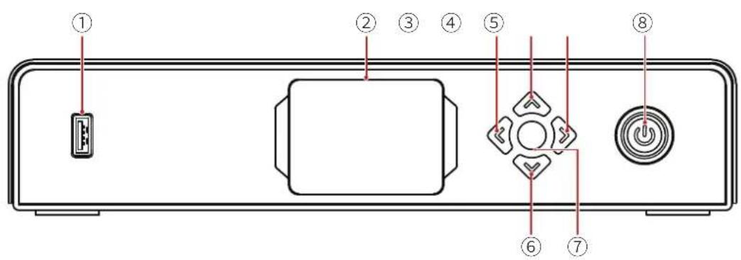
① USB Port
② Display Screen
③ Left Key
④ Up Key
⑤ Right Key
⑥ Down Key
⑦ Menu/Confirm Button (long press to enter the menu/press to confirm)
⑧ Power Button (red: off; green: on)
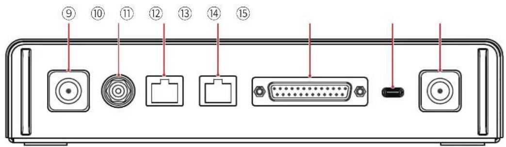
⑨ Antenna Connector
⑩ DC Input
⑪ Tally Input RJ45 Port
⑫ Switcher Loopout RJ45 Port
⑬ Tally Input Port (DB25 F)
⑭ USB-C Port (reserved)
⑮ Antenna Connector
Tally Box Introduction
1.2 Interface

① RJ45 Port Connection Status
② Tally Light Normal Status
③ Tally Light PGM Status
④ Tally Light PVW Status
1.3 Installing the Tally Box

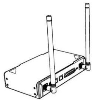
①
① Install the antennas as shown in the diagram.

②

③
② Connect the power adapter.
③ Press the power button to turn the Tally box on.
Tally Box Introduction
1.4 Operations
1.4.1 Learning the Sequence
① Preparing the devices
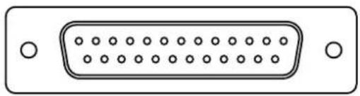
- Confirm the supported Tally port on the switcher.
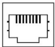
RJ45 DB25
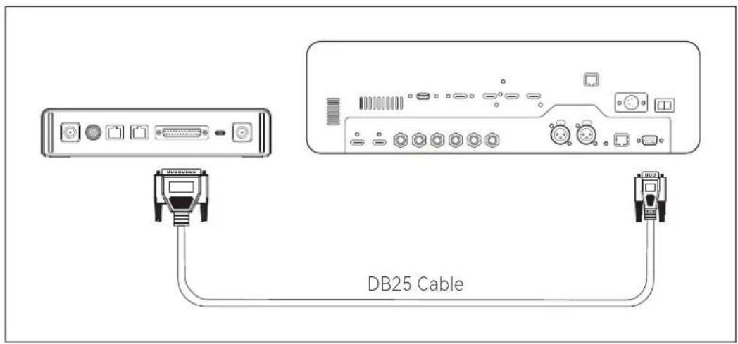
- Connect the Tally box and switcher using the corresponding cable.

• Power on the Tally box, Tally light, and switcher.
- Press any PGM and PVW buttons except for 1, for example, PGM 2 and PVW 3.
Tally Box Introduction
② Learning the PGM and PVW sequence
- Long press the menu button to enter the menu, choose the Sequence Learning function, and select the corresponding port based on the supported Tally port on the switcher.

![graph TD A["DB25"] --> B["RJ45"] B --> C["USB-C"] D["Return"] --> B](/content/2026/07/1442228/images/0913db2df8fcb8d4e85ed10e19163d67f9eaaf96d49f786996c764fe0cfc5433.jpg)
- Press any PGM button except PGM1 within 10 seconds to enter the PGM sequence learning interface.

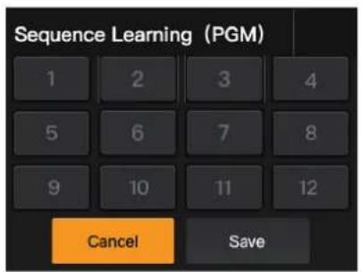
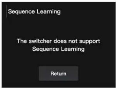
- Note that if there are no valid operations within 10 seconds, the interface will display "The switcher does not support Sequence Learning". In case of a timeout, repeat the previous steps.
Tally Box Introduction
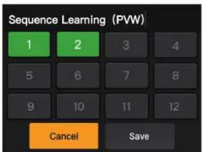
- After entering the PGM sequence learning interface, press the corresponding PGM button on the switcher that matches the number blinking on the learning interface. For example, if number 1 is blinking, press PGM1 on the switcher. After the first learning, the blinking number will sequentially switch to the next. For example, after the learning of PGM1, number 2 will start blinking. Continue with learning one by one.

Note: One number can only match one PGM button.
- After the PGM sequence learning is completed, the Tally box will display the PVW sequence learning interface. Press any PVW button except PVW1 within 10 seconds to enter the PVW sequence learning interface.

• After entering the PVW sequence learning interface, refer to the PGM sequence learning steps to complete the PVW sequence learning.
Tally Box Introduction
- If a key conflict is detected in the PVW sequence learning process, the Tally box will display "Please press PGM1 to avoid key conflicts". Follow the instruction to continue with the sequence learning.

- Continue with the sequence learning until "Sequence Learning Completed" is displayed.

1.4.2 Switcher IP Address
① Preparing the devices
- Connect the Tally box and switcher using an Ethernet cable.
• Power on the Tally box, Tally light, and switcher.
② Configuring the IP address
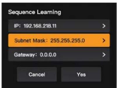
- Long press the menu button to enter the menu, and choose Switcher IP Address.

Tally Box Introduction
- Set the IP address, subnet mask, and gateway to the same as the switcher.
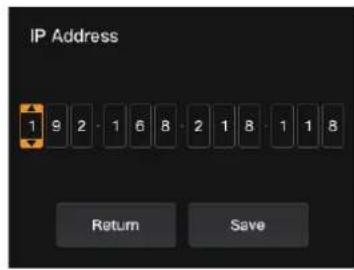


- Click Yes.


1.4.3 Adjusting the Brightness
- Long press the menu button to enter the menu, and choose Brightness Control.

• Four levels are available to adjust the brightness of all Tally lights.

Note: Brightness adjustment on the side of the Tally light will not affect brightness settings on the side of the Tally box.
Tally Box Introduction
1.4.4 Device IP Address
- Long press the menu button to enter the menu, choose Settings, and then select Device IP Address.


- The Tally box supports manual configuration of the IP address, subnet mask, and gateway.
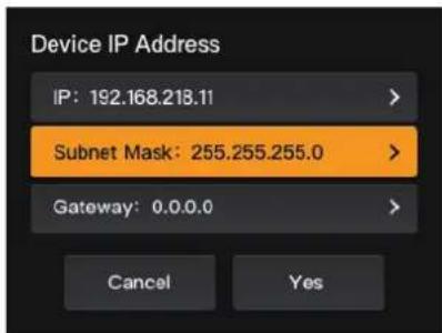
Note: When configuring the IP address through Switcher IP Address, the IP of the Tally box will automatically change to the same as the switcher.
1.4.5 Upgrading the Tally Box
- Download the firmware upgrade program and new firmware to your computer, and then open the program.
- Connect the box and computer through a USB-A to USB-C cable. Wait for the firmware upgrade program to detect the connection.
Tally Box Introduction

- Click Yes to start the upgrade process. Do not turn off the Tally box or unplug the cable during the process to avoid upgrade failures.

- After the upgrade process is completed, the program and box will display "Tally Upgrade Successful", and then you can unplug the cable.

Note: The firmware installation file for the Tally box can be obtained from Hollyland's technical support or official website.
Tally Light Introduction
2.1 Overview
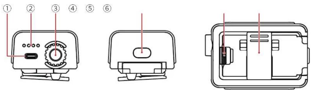
① USB-C Port (for charging, upgrading and pairing)
② Battery Level LED
③ Tally Light Number Control Dial
④ Power Button (press and hold for 3s to power on/off; double press after startup to adjust Tally light brightness)
⑤ Battery Compartment Switch
⑥ Back Clip
2.2 Installing the Tally Light

① Install the battery.
Tally Light Introduction
![graph LR A["Power outlet"] --> B["Radio station"] B --> C["Wireless sensor"] C --> D["Video camera 1"] C --> E["Video camera 2"] C --> F["Video camera 3"] C --> G["Video camera 4"] style A fill:#f9f,stroke:#333 style D fill:#ccf,stroke:#333 style E fill:#ccf,stroke:#333 style F fill:#ccf,stroke:#333…](/content/2026/07/1442228/images/7df74f0ce86e557ea12e4cab6182276c1136bc566c676cffe5199f2f608f6821.jpg)
② Install the Tally light on the shooting device as shown in the diagram.

③ Press the power button for 3 seconds to turn on the Tally light.
Tally Light Introduction
2.3 Operations
2.3.1 Tally Light Colors
| Solid | Colorless | Non-PGM/PVW |
| Red | PGM | |
| Green | PVW | |
| Quick Flash Green | Tally light upgrading | |
| Slow Flash Yellow | Tally light not connected, and brightness adjusted to the first level | |
2.3.2 Pairing the Tally Light
- Use a USB-C to USB-A cable to connect the Tally light to the Tally box.
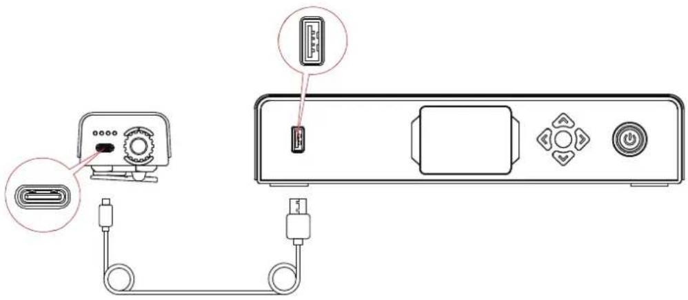
- Wait for the Tally box to display the pairing interface, and then clickYes.


Note: After pairing, you still need to manually select the number by rotating the number control dial.
Tally Light Introduction
2.3.3 Upgrading the Tally Light
- Use a USB-C to USB-A cable to connect the Tally light to the Tally box. Wait for the Tally box to display the upgrade interface.
- Click Yes to start the upgrade process. Do not turn off the Tally box or Tally light or unplug the USB cable during the process to avoid upgrade failures.

- During the upgrade process, the Tally light will flash green fast until the upgrade is completed.
- After the upgrade process is completed, the Tally box will display "Tally Upgrade Successful", and the Tally light will return to its former working state after a solid green light for 3 seconds.

Note: Before upgrading the Tally light, ensure the Tally box has been upgraded.
Compatibility List
| Brand Model Cable No. | |||
| Datavideo | SE2800 DB25 Male to DB25 Male | 2 | |
| HS1200 DB25 Male to HDB15 Female | 5 | ||
| Panasonic | AV-HS6000MC DB25 Male to DB25 Male | 2 | |
| AV-HS410MC DB25 Male to Dual DB15 Male | 6 | ||
| Sony | MCX-500 DB25 Male to DB9 Female | 3 | |
| BMD | ATEM Mini Pro Ethernet Cable | 1 | |
| ATEM Mini Extreme ISO Ethernet Cable | 1 | ||
| ATEM 1 M/E Constellation HD Ethernet Cable | 1 | ||
| ATEM Television Studio Pro 4K Ethernet Cable | 1 | ||
| ATEM 1 M/E Production Studio 8K Ethernet Cable | 1 | ||
| Roland | Roland V-60HD | DB25 Male to DB25 Male | 2 |
| Roland V-600UHD | DB25 Male to DB25 Male | 2 | |
| Roland V-800HD | DB25 Male to Dual HDB15 Male | 7 | |
| Roland V-1200HD | DB25 Male to DB25 Male | 2 | |
| vMix | vMix | Ethernet Cable | 1 |
| DeviceWell | DeviceWell HDS7305 | DB25 Male to HDB15 Male | 4 |
Cable
① CAT5 Cable
② Tally Cable (DB25 Male to DB25 Male)
③ Tally Cable (DB25 Male to DB9 Female)
④ Tally Cable (DB25 Male to HDB15 Male)
⑤ Tally Cable (DB25 Male to HDB15 Female)
⑥ Tally Cable (DB25 Male to Dual DB15 Male)
⑦ Tally Cable (DB25 Male to Dual HDB15 Male)
Specifications
| Tally Light Tally Box | ||
| LOS Range | 2,625ft (800m) | |
| Operating Frequency | 2.4 GHz | |
| Modulation Mode | LORA | |
| Receiver Sensitivity | < -115 dBm | |
| Latency | < 150ms | |
| Battery Life | >8 hours | |
| Dimensions(L × W × H) | 77.8 × 50.5 × 37.4mm | 142.5 × 232.8 × 50.1mm |
| Weight | ≈ 85g ≈ 1,262g | |
| Temperature | Working: 32°F to 113°F (0°C to 45°C)Storage: 14°F to 140°F (-10°C to 60°C) | |
Support
If you encounter any problems in using the product or need any help, please contact the Hollyland Support Team via the following ways:
Hollyland User Group
f HollylandTech
HollylandTech
YouTube HollylandTech
support@hollyland.com
www.hollyland.com
Statement
All copyrights belong to Shenzhen Hollyland Technology Co., Ltd. Without the written approval of Shenzhen Hollyland Technology Co., Ltd., no organization or individual may copy or reproduce part or all of any written or illustrative content and disseminate it in any form.
Trademark Statement
All the trademarks are owned by Shenzhen Hollyland Technology Co., Ltd.
Note
Due to product version upgrades or other reasons, this User Manual will be updated from time to time. Unless otherwise agreed, this document is provided as a guide for use only. All representations, information, and recommendations in this document do not constitute warranties of any kind, express or implied.
Manufacturer: Shenzhen Hollyland Technology Co., Ltd.
Address: 8F, 5D Building, Skyworth Innovation Valley, Tangtou Road, Shiyan Street, Baoan District, Shenzhen, 518108, China
MADE IN CHINA
HOLLYVIEW
Powered by Hollyland



- WIRELESS TALLY SYSTEM
- CONTENTS
- CONTENTS....2
- SAFETY PRECAUTIONS....3
- TALLY BOX INTRODUCTION......4
- TALLY LIGHT INTRODUCTION....13
- COMPATIBILITY LIST....17
- SPECIFICATIONS....18
- DISCLAIMER....19
- SAFETY PRECAUTIONS
- TALLY BOX INTRODUCTION
- 1.1 OVERVIEW
- 1.2 INTERFACE
- 1.3 INSTALLING THE TALLY BOX
- 1.4 OPERATIONS
- 1.4.1 LEARNING THE SEQUENCE
- ① PREPARING THE DEVICES
- ② LEARNING THE PGM AND PVW SEQUENCE
- 1.4.2 SWITCHER IP ADDRESS
- 1.4.3 ADJUSTING THE BRIGHTNESS
- 1.4.4 DEVICE IP ADDRESS
- 1.4.5 UPGRADING THE TALLY BOX
- TALLY LIGHT INTRODUCTION
- 2.1 OVERVIEW
- 2.2 INSTALLING THE TALLY LIGHT
- 2.3 OPERATIONS
- 2.3.1 TALLY LIGHT COLORS
- 2.3.2 PAIRING THE TALLY LIGHT
- 2.3.3 UPGRADING THE TALLY LIGHT
- COMPATIBILITY LIST
- CABLE
- SPECIFICATIONS
- SUPPORT
- STATEMENT
- TRADEMARK STATEMENT
- NOTE
- HOLLYVIEW
- POWERED BY HOLLYLAND
Marque : Hollyland
Modèle : Wireless Tally System
Catégorie : Interphone