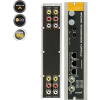
T.0X QUAD 563822 - Modulateur TV TELEVES - Notice d'utilisation et mode d'emploi gratuit
Retrouvez gratuitement la notice de l'appareil T.0X QUAD 563822 TELEVES au format PDF.


| Type de produit | Amplificateur multiswitch pour satellite et TNT |
| Marque | Televes |
| Modèle | T.0X QUAD 563822 |
| Dimensions (L x l x H) | 150 x 100 x 40 mm |
| Poids | 200 g |
| Alimentation | 12 V CC, 500 mA (via adaptateur secteur) |
| Nombre de sorties | 4 (Quad) |
| Entrées | 1 entrée satellite, 1 entrée terrestre (TNT) |
| Fréquence satellite | 950 – 2150 MHz |
| Fréquence terrestre | 47 – 862 MHz |
| Compatibilité DiSEqC | Oui, DiSEqC 1.0/2.0 |
| Fonctions principales | Distribution de signaux satellite et TNT vers 4 récepteurs, amplification intégrée, filtres intégrés |
| Entretien et nettoyage | Nettoyer avec un chiffon doux et sec. Ne pas utiliser de produits liquides ou abrasifs. |
| Sécurité | Utiliser uniquement en intérieur. Ne pas exposer à l'humidité ou aux intempéries. Débrancher avant tout entretien. |
| Pièces détachées et réparabilité | Aucune pièce détachable par l'utilisateur. Contacter le service après-vente Televes pour toute réparation. |
| Informations générales | Fabriqué par Televes, Espagne. Garantie : 2 ans. Température de fonctionnement : -5°C à +40°C. |
FOIRE AUX QUESTIONS - T.0X QUAD 563822 TELEVES
Questions des utilisateurs sur T.0X QUAD 563822 TELEVES
0 question sur cet appareil. Repondez a celles que vous connaissez ou posez la votre.
Poser une nouvelle question sur cet appareil
Téléchargez la notice de votre Modulateur TV au format PDF gratuitement ! Retrouvez votre notice T.0X QUAD 563822 - TELEVES et reprennez votre appareil électronique en main. Sur cette page sont publiés tous les documents nécessaires à l'utilisation de votre appareil T.0X QUAD 563822 de la marque TELEVES.
MODE D'EMPLOI T.0X QUAD 563822 TELEVES
Televes®

T. □> < SERIES
Ref. 563822

HDTV ENCODER/MODULATOR - Quad Composite to COFDM/QAM
QUICK
INSTALLATION GUIDE
Safety instructions
Caution statements
Product inspection - Inspect the equipment for shipping damage. Should any damage be discovered, immediately file a claim with the carrier.
Important Safety Instructions - To ensure proper installation and operation, take a moment to read this guide before proceeding with the installation. If you have any questions or comments about the T.OX Series - Encoders, please contact your dealer.
WARNING:
TO PREVENT FIRE OR ELECTRICAL SHOCK DO NOT EXPOSE TO RAIN OR MOISTURE.

CAUTION
RISK OF ELECTRIC SHOCK DO NOT OPEN

CAUTION:
TO REDUCE THE RISK OF ELECTRIC SHOCK, DO NOT REMOVE COVER.
NO USER-SERVICEABLE PARTS INSIDE.
REFER SERVICING TO QUALIFIED
PERSONNEL.

A product and cart combination should be moved with care. Quick stops, excessive force and uneven surfaces may cause the product and cart combination to overturn.

The lightning flash with arrow head symbol, within an equilateral triangle, is intended to alert the user to the presence of uninsulated "dangerous voltage" within the product's enclosure that may be of sufficient magnitude to constitute a risk of electric shock to persons.

The exclamation point within an equilateral triangle is intended to alert the user to the presence of important operating and maintenance (servicing) instructions in the literature accompanying the product.
WARNING:
TO REDUCE THE RISK OF FIRE OR ELECTRIC SHOCK, DO NOT EXPOSE THIS PRODUCT TO RAIN OR MOISTURE.
DO NOT OPEN THE CABINET,
REFER SERVICING TO QUALIFIED PERSONAL ONLY.
CAUTION:
TO PREVENT ELECTRIC SHOCK, DO NOT USE THIS (POLARIZED) PLUG WITH AN EXTENSION CORD RECEPTACLE OR OTHER OUTLET UNLESS THE BLADES CAN BE FULLY INSERTED TO PREVENT BLADE EXPOSURE.
Important Safety Instructions
-
Read and Follow All Instructions - All the safety and operating instructions should be read prior to and followed while operating this product.
-
Retain Instructions - The safety and operating instructions should be retained for future reference.
-
Heed Warnings - All warnings on the product and in the operating instructions should be adhered to.
-
Cleaning - Disconnect this product from any electrical source before cleaning. Use a damp cloth; do not use liquid or aerosol cleaners.
-
Attachments - Do not use attachments that are not recommended by the product manufacturer as they may cause hazards.
-
Water and Moisture - Do not use this product near any source of water.
-
Mounting - Do not place this product on an unstable cart, stand, tripod, bracket, or table. The product may fall, causing serious injury to persons or nearby objects, and serious damage to this product. Use only with a cart, stand, tripod, bracket, or table recommended by the manufacturer, or sold with the product. Any mounting of the product should follow the manufacturer's instructions, and should use a mounting accessory recommended by the manufacturer.
-
Ventilation - Slots and openings in the chassis or cabinet are provided for ventilation and to ensure reliable operation of the product. These openings should never be blocked or covered in any way. This product should not be placed in any case, cabinet, or rack unless proper ventilation is provided and the manufacturer's instructions have been adhered to.
-
Power Sources - This product should be operated only from the type of power source indicated on the label.
-
Grounding or Polarization - Do not bypass or defeat electrical plug polarization or grounding. Doing so will violate the warranty and may pose a risk of fire or electrocution.
-
Wire Protection - Ensure all connected wiring is routed correctly to avoid damage including pinching, excessive bends, or compression.
-
Electrical Supply, Grounding, and Surge Protection – Ensure that all local or national electrical codes are followed. Seek the advice of a licensed electrician, professional engineer, or other licensed expert.
-
Power Lines - Always use caution and avoid operating this or any connected equipment near uninsulated power line or any other hazards.
-
Object and Liquid Entry - Never allow objects or liquid of any kind into this product through openings. Doing so could result in fire or electric shock.
-
Servicing - There are no user serviceable parts. Do not attempt to service this product or remove covers. Doing so may expose you to dangerous voltage or other hazards. Refer all servicing to qualified service personnel. Examples of damage requiring service include but are not limited to:
• Damage to power-supply wiring.
- If liquid has been spilled, or objects have fallen into the product.
- If the product has been exposed to rain or water.
- If the product does not operate normally by following the operating instructions. Adjust only those controls that are covered by the operating instructions as an improper adjustment of other controls may result in damage and will often require extensive work by a qualified technician to restore the product to its normal operation.
- If the product has been dropped or physically damaged.
- When the product exhibits a distinct change in performance.
-
Replacement Parts - Ensure that repairs are performed by qualified technicians and that only manufacturer supplied or authorized parts are used.
-
Safety Check - Upon completion of any service or repairs to this product, ensure safety checks to determine that the product is functioning per manufacturer specifications are performed.
-
Heat - The product should be situated away from heat sources such as radiators, heat registers, stoves, or other products (including amplifiers) that produce heat. Ensure that ambient temperature is maintained in the manufacturer specified operating range.
Description of connectors
Front view

Rear view
![① ② ③ ④ ⑤ ⑥ ⑦ ⑧ Input 1 Input 2 [USB1 USB2] Input 3 Input 4](/content/2026/07/1437690/images/6882493edc39a21b20ba0cb59494f98fb7637148b4c447bf13b43b4d2280b5bc.jpg)
1.- Power connectors
2.- Ethernet connector
3.- Ethernet connector
4.- Programmer connector
5.- RF loop through input
6.- RF output
1.- CVBS input. Channel 1
2.- Analog (L/R) audio input. Channel 1
3.- CVBS input. Channel 2
4.- Analog (L/R) audio input. Channel 2
5.- CVBS input. Channel 3
6.- Analog (L/R) audio input. Channel 3
7.- CVBS input. Channel 4
8.- Analog (L/R) audio input. Channel 4
LED indicators
| Front LED alarms | TEMP | Color Internal temp Comment | ||
| Solid green Normal Safe | ||||
| Slow blink orange High Warning | ||||
| Fast blink red Very High Danger | ||||
| CH1/CH2 - CH3/CH4 | Color Channel status Comment | |||
| Off Disabled Channels disabled. | ||||
| Solid green Lock Inputs locked and unit encoding audio/video. | ||||
| Solid red Unlock Inputs unlocked and unit not encoding audio/video. | ||||
| Blinking red | Boot Unit starting up. | |||
| Solid yellow | Partial lock | Only one of the two inputs is locked and encoding audio/video. | ||
| OUTPUT | Color Output mode Comment | |||
| Solid green Normal Output RF channel is ON, broadcasting audio/video (normal mode). | ||||
| Slow blinking green | Carrier wave, null or muted | Output RF channel is OFF or in an alternate signal mode. | ||
| Solid orange/red | Normal Config bitrate doesn't fit in output | |||
| LOOP | Color | Output loop status | Comment | |
| Solid green | ON | Output loop-through enabled. Units may be daisy-chained using the internal combiner. | ||
| Off OFF | Output loop-through disabled. Units must be combined using an external combiner. | |||
Installation
- Install all units in the rack and connect them as shown in Figure 1.

Figure 1
- The audio and video input signals connect to the back of the modules.
![graph TD A["Top Panel"] --> B["Left Panel"] A --> C["Right Panel"] A --> D["Bottom Panel"] E["Left Panel"] --> F["Left Panel"] E --> G["Right Panel"] E --> H["Bottom Panel"] I["Right Panel"] --> J["Left Panel"] I --> K["Right Panel"] I --> L["Bottom Panel"]](/content/2026/07/1437690/images/b05a41a77c7fdb42cc0f2c0dbff10bde7ff70ce7321310c6135a75c4871e4f6a.jpg)
Figure 2
- If a network is available that provides IP addresses through DHCP, connect the encoders to the network as shown in Figure 3. If such a network is not available, then a computer will need to be connected as shown in Figure 4.
![graph TD A["Teles"] --> B["Server"] B --> C["Computer"] C --> D["Network with DHCP server"] D --> E["Client Rack"] style A fill:#f9f,stroke:#333 style B fill:#ccf,stroke:#333 style C fill:#cfc,stroke:#333 style D fill:#fcc,stroke:#333 style E fill:#ffc,stroke:#333](/content/2026/07/1437690/images/409ab7492f06fe595df959e08ec4ce49948d7d6b23672f484ddf1e6124dc086f.jpg)
Figure 3 - Rack with DHCP server.
- Power on the units.
![graph TD A["Base Station 1"] -->|Cable Link| B["Server"] C["Base Station 2"] -->|Cable Link| B D["Base Station 3"] -->|Cable Link| B E["Base Station 4"] -->|Cable Link| B F["Base Station 5"] -->|Cable Link| B G["Base Station 6"] -->|Cable Link| B H["Base Station 7"] -->|Cable Link| B I["Base Station…](/content/2026/07/1437690/images/a84f5c6224833d634a648f24ecdb864d6823b0c6dbe6280204545a679878b941.jpg)
Figure 4 - Rack without DHCP server.
- Connect the programmer to each unit and set a unique number in the "#ID" field according to the order of installation of the units in the rack.
![graph TD A["Teles"] --> B["Base Station 0001"] A --> C["Base Station 0007"] B --> D["Device"] C --> D style A fill:#f9f,stroke:#333 style B fill:#ccf,stroke:#333 style C fill:#ccf,stroke:#333 style D fill:#dfd,stroke:#333](/content/2026/07/1437690/images/8832e691480a00a7d81e085b332a31f29edc138e89d605847de3a45b9dcb9f14.jpg)
Figure 5 - Set a # number different for each unit.
- Connect the programmer to a unit, usually the first one, and read the IP address. Each unit can work as a master controller for the other units. All units can be configured by connecting to only one.
![graph TD A["Televes"] --> B["Network"] B --> C["IP ADDRESS: 101.101.103.89?"] C --> D["Device"]](/content/2026/07/1437690/images/20f7304645eef51142a7d5758edf71516adac97d082e4af12d39abd6fd6911a4.jpg)
Figure 6 - Read the IP address of one unit.
- If a network was connected in Step 3 then proceed to step 8. If not, set the address of you computer as follows:
IP value = 172.20.0.2
netmask = 255.0.0.0
gateway = 172.20.0.3
NOTE: The default factory configuration of the units has an IP address in this range (it should be different for each unit). If a unit was ever provided an address before, manually or through DHCP, this unique address may no longer exist. Resetting to IP factory defaults, will return the original unique private address though.
- In your web browser, enter the IP address from Step 6 as the URL. A login prompt will appear. By default the parameters are:
Login: encoder
Password: encoder
The Status > Summary page should appear as the first page. This provides a summary of all the units installed in the network and the units will be sorted by the number entered in Step 5.
The "Change Password" option only changes the password of the encoder currently logged in to. To change the password for the remaining modules, each one will need to be logged into with its unique IP address and the change made for each.
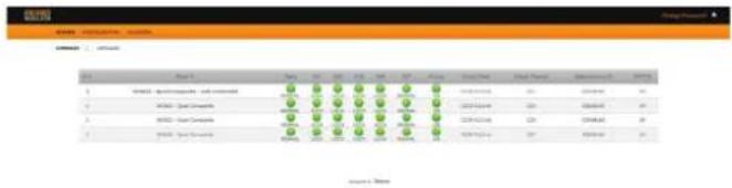
Figure 7 - Status > Summary tab.
Some items have an automatic configuration option, such as "Automatic channel numbering" shown in figure 10.

Figure 10 - Configuration > Transport tab.
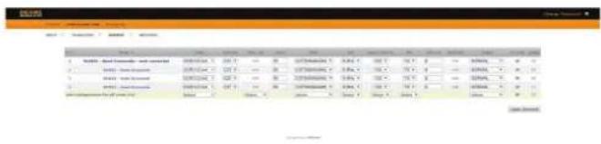
Figure 11 - Configuration > Output tab.
Figure 8 shows an example of a detailed status page.
| 序号 | Symbol | P | Description | Type | Sample/Panel | Description | Sample/Group |
| 1 | HMM1 - Boid Enzyme - Bcl pinnaeA2 | 20250 | 0000000000 | BCL C39 | 1. 16.878. 17.418. 17.418. 17.418. 17.418. 17.418. 17.418. 17.418. 17.418. 17.418. 17.418. 17.418. 17.418. 17.418. 20250 | HMM1 - Boid Enzyme - Bcl pinnaeA2 | DMS/Pc (control) |
| 2 | Hmcrb - Biot Conocort | 20250 | 0000000000 | BCL C39 | 1. 16.878. 17.418. 17.418. 17.418. 17.418. 17.418. 17.418. 17.418. 17.418. 20250 | Hmcrb - Biot Conocort | DMS/Pc (control) |
| 3 | HMM2 - Biot Conocort | 20250 | 0000000000 | BCL C39 | 1. 16.878. 17.418. 17.418. 17.418. 17.418. 17.418. 17.418. 17.418. 20250 | Hmcrb - Biot Conocort | DMS/Pc (control) |
| 4 | Hmcrb - Biot Conocort | 20250 | 0000000000 | BCL C39 | 1. 16.878. 17.418. 17.418. 17.418. 17.418. 20250 | Hmcrb - Biot Conocort | dMS/Pc (control) |
Figure 8 - Status > Detailed tab.
The network configuration page allows a change to the Number assigned in Step 5. This option also has an "Auto" assignment feature.
The "Auto" option will ask for confirmation since it will overwrite the settings of all units set in Step 5 and the ordering will likely not be as the units were placed in the rack.

Figure 12 - Configuration > Network tab.
9. Configure all units:
Select "CONFIGURATION". This page has 4 options, INPUT, TRANSPORT, OUTPUT, and NETWORK, shown in Figures 9, 10, 11, and 12 respectively. For each configuration page, the last column is "Select". Any changes made, will be saved only to the units with this associated "Select" box checked when "Apply Selected" is clicked. This applies to all 4 of the sections under the Configuration Menu.
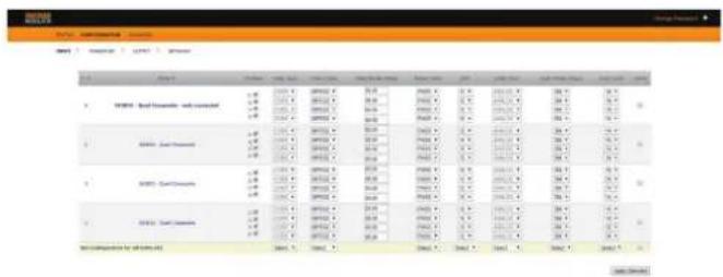
Figure 9 - Configuration > Input tab.
Clicking on the unit name, a new window is opened and show the unit settings summary.
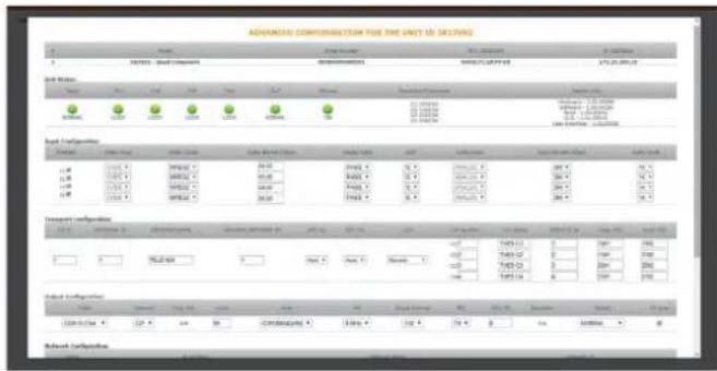
Figure 13 - Advanced configuration
Menu flow chart
For programming Unit operation
![graph TD A["MAIN"] --> B["SELECT A/V INPUT INPUT 1"] B --> C["INPUT 1 - STATUS ENABLED"] C --> D["INPUT 1 - ASSIGN PIDs VIDEO 1001 AUDIO 1002"] D --> E["INPUT 1 - SERU_NAME: TUES C1"] E --> F["INPUT 1 - SERVICE ID 00001"] F --> G["INPUT 1 - AUDIO CONFLEVEL: 14 RATE:384Kbps"] G --> H["INPUT 1 - VIDEO…](/content/2026/07/1437690/images/5bb0be03e6ec73c70e8ab259bd6bd4a17794285cf5a9785ed87503e571b91e3c.jpg)
Technical specifications
| References 563822 | ||||
| INPUTS | VIDEO Connectors | 4 sets - 1x RCA for Video (CVBS) | ||
| AUDIO Connectors 4 sets - 2x RCA for Analog Audio (L, R) | ||||
| OUTPUT | Connectors "F" Female (loop-through combiner input) | |||
| ENCODING PROFILE | VIDEO | Output Format MPEG-2 / H.264 | ||
| Resolution | 480I & 576iSupports auto-scan for input resolution | |||
| Aspect Ratio 4:3, 16:9 and pass through | ||||
| GOP 10, 12, 15, 16, 18, 20, 24 or 30 | ||||
| Transport rate Variable | ||||
| Video bit rate Variable | ||||
| AUDIO | Output format MPEG1 Layer 2 | |||
| Sampling rate kHz 48 | ||||
| Output bitrate | Variable | |||
| OUTPUT | RF | Connectors 1x "F" Female | ||
| Frequency Range | MHz | 46 - 862 | ||
| Max output level | dBμV | +115 (+103 with loop-through) | ||
| MER | dB | >40 (typ) | ||
| Spurious | dBc | -60 | ||
| Impedance | Ω | 75 | ||
| I/Q Phase Error | ° | <1 | ||
| I/Q Amplitude Imbalance | % | <1 | ||
| QAM | Modulation format | 16, 32, 64, 128, 256 | ||
| BaudRate | Mbaud | 6,9 | ||
| Roll-off | % | 15 | ||
| Code | Reed Solomon | |||
| Spectrum Mode | Normal / Inverted | |||
| Frequency Step | KHz | 250 | ||
| COFDM | Modulation format QPSK, 16QAM, 64QAM | |||
| Guard Interval 1/4, 1/8, 1/16, 1/32 | ||||
| FEC | 1/2, 2/3, 3/4, 5/6, 7/8 | |||
| Bandwidth | MHz | 6, 7, 8 | ||
| Cell_id | Editable | |||
| Frequency Step | KHz | 125 / 166 | ||
| PSI PARAMETERS | Transport Stream ID | Editable | ||
| Original Network ID | Editable | |||
| Network ID | Editable | |||
| Logical Channel Number | Editable | |||
| NIT Version | Manual / Automatic | |||
| SDT Version | Manual / Automatic | |||
| Type LCN | Generic / UK / NorDig V1 / NorDig V2 | |||
| Network Name | Editable | |||
| Service PID | Editable | |||
| Service Name | Editable | |||
| Service ID | Editable | |||
| MONITORING / CONTROL | Local control Full configuration with LCD handheld programmer | |||
| Local monitoring | LOOP status LED | |||
| OUTPUT status LED | ||||
| TEMP status LED | ||||
| CH1/CH2 - CH3/CH4 status LEDs | ||||
| Ethernet status LEDs | ||||
| Remote monitoring | Centralized web based remote control, management, alarms, and software upgrades | |||
| Control | Daisy-chain integrated ethernet switch | |||
| GENERAL | Power supply | Vdc 24 | ||
| Power disipation | W | <16 | ||
| Operating Temperature | °F / °C | 32 to 113 / 0 to 45 | ||
televes.com
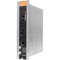
Marque : TELEVES
Modèle : T.0X QUAD 563822
Catégorie : Modulateur TV