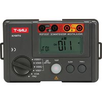
UT501A - équipements de mesure Uni-T - Notice d'utilisation et mode d'emploi gratuit
Retrouvez gratuitement la notice de l'appareil UT501A Uni-T au format PDF.


| Type de produit | Mégohmmètre numérique (testeur d'isolement) |
| Marque | Uni-T |
| Modèle | UT501A |
| Dimensions (L x l x h) | Environ 130 x 70 x 35 mm |
| Poids | Environ 200 g (sans piles) |
| Alimentation | 6 piles 1,5 V AA (LR6) |
| Tensions d'essai | 500 V / 1000 V |
| Plage de mesure d'isolement | 0,1 MΩ à 2000 MΩ |
| Continuité | Oui, avec alarme sonore |
| Fonctions principales | Test d'isolement, continuité, mesure de tension AC/DC (facultatif) |
| Affichage | Écran LCD rétroéclairé |
| Entretien et nettoyage | Nettoyer avec un chiffon humide, pas de solvants |
| Sécurité | CAT II 300 V, double isolation |
| Pièces détachées et réparabilité | Piles et fusibles remplaçables par l'utilisateur |
| Informations générales | Utilisation intérieure, altitude max 2000 m |
FOIRE AUX QUESTIONS - UT501A Uni-T
Questions des utilisateurs sur UT501A Uni-T
0 question sur cet appareil. Repondez a celles que vous connaissez ou posez la votre.
Poser une nouvelle question sur cet appareil
Téléchargez la notice de votre équipements de mesure au format PDF gratuitement ! Retrouvez votre notice UT501A - Uni-T et reprennez votre appareil électronique en main. Sur cette page sont publiés tous les documents nécessaires à l'utilisation de votre appareil UT501A de la marque Uni-T.
MODE D'EMPLOI UT501A Uni-T
UT501A
Operating Manual

Insulation resistance tester
I. Overview
UT501A Insulation Resistance Tester is designed with brand-new design and combination of massive integrated and digital circuits; it can measure insulation resistance, AC voltage, etc. and enjoys high degree of accuracy, stable performance, easy operation and reliability. It is used for insulation resistance measurement for insulation materials and various kinds of electric equipments such as transformer, electric machines, cables, switches, electrical appliances, a ideal tool for electric equipment maintenance, testing and inspection.
II. Safety Information
UT501A is designed and manufactured in compliance with: IEC61010-1 CATIII 600V, Double Insulation and Pollution Degree 2 standards. Operate as specified in the manual, otherwise the protection offered by the tester would be impaired.
Compliance Standards: EN61010-1:2010 ; EN61010-2-030:2010 ; EN61557-1:2007
EN61557-2:2007 ; EN61326-1:2013 ; EN61326-2-2:2013
Safety Symbols 1
| Danger | Identifies conditions and actions that may pose hazard to the users. | |
| Warning | Alerts users to avoid electric shock. | |
| Caution | Identifies conditions and actions that may cause damage to the instrument or affect accurate measurement. |
Danger
- Do not measure any AC circuit with voltages above 750V.
- Do not measure in flammable places. Spark may cause explosion.
- In case that the surface of the instrument is wet or the operator's hands are wet, please do not operate this instrument.
● Do not touch the electric conduction parts of test leads when testing.
● Do not open the battery cover when testing. - When insulation resistance is measured, do not touch the electric wire under test.
Warning
- Stop using the instrument if it works abnormally. For example: the equipment is damaged or metal parts are exposed.
● Operator must be careful when voltage exceeds 33Vrms, 46.7Vacrms or 70Vdc. Such kinds of voltage may cause electric shock. - Do not replace the battery in wet conditions.
- Ensure that all test wires are connected to the test ports of tester securely.
- When opening the battery cover, make sure that the instrument is turned off.
- Please read carefully and understand the manual before using the instrument.
- Use the instrument as specified in the manual at any time and store the manual for further reference.
- When the instrument is testing, misoperation may lead to an accident and damage of equipment.
Caution
● Before testing insulation resistance, the circuit under test must be completely discharged and completely isolated with other power circuits.
- In case the test pen is damaged and needs to be replaced, use only the test leads with the same model or identical electrical specifications.
- When the battery indicator (☐) indicates that the power runs out, do not use the instrument. Remove the battery and store the instrument if it is not in use for a long time.
- Do not store or use this instrument in heat, humid, flammable, explosive and strong electromagnetic field environments.
Safety Symbols 2
| The instrument has double insulation or reinforced insulation. | |
| ACV | AC Voltage |
| 1/2 | Ground |
| CE | Comply with European Union standards |
III. Technical Specification
| Accuracy | ±(a% reading + digits); calibration per year. |
| Ambient temperature: | (23 ± 5)° C |
| Environmental humidity: | 45% to 75% |
- Insulation Resistance Measurement
| Rated Voltage | 100V | 250V | 500V | 1000V |
| Test Range | 0.00MΩ~5.5GΩ(When it is about less than 4.0MΩ, buzzer outputs alarming sounds). Notes: (100V) 0.00MΩ~100MΩ | |||
| Opened Voltage | DC100V±10% | DC250V±10% | DC500V±10% | DC1000V±10% |
| Rated Test Current | When load is 100KΩ, the rated testing current is 0.9mA ~1.1mA. | When load is 250KΩ, the rated testing current is 0.9mA ~1.1mA. | When load is 500KΩ, the rated testing current is 0.9mA ~1.1mA. | When load is 1 MΩ, the rated testing current is 0.9mA ~1.1mA. |
| Shorted Current | About less than 1.8mA. | |||
| Accuracy | 0.00MΩ~99MΩ: ±(3%+5digits); 100MΩ~5.5GΩ: ±(5%+5digits) | |||
- Voltage Measurement
| AC Voltage | |
| Test Range | 30V~750V(50Hz/60 Hz) |
| Resolution | 1V |
| Accuracy | ± (2%+3digits) |
● Display: LCD, 1999 count.
● Low Battery Indication: " [REDACTED] "
● Overload Indication: ">5.5GΩ" for insulation resistance measurement; "OL V" for voltage measurement.
● Autoranging.
● Discharge voltage automatically.
● Backlight, suitable in dark site.
● Red warning light (warning light is on when high voltage outputs).
● Working conditions: 0°C\~35°C; relative humidity is 75% or less; altitude: 2000m.
● Storage conditions: -20°C\~60°C/ relative humidity is 80% or less.
● Dimensions: 150mm (L) × 100mm (W) × 71mm (D).
● Power supply: alkaline batteries, 1.5V (5#) ×6.
● Weight: 0.5kg (with battery).
● Accessories: test leads, instruction manual, carrying case, gallus.
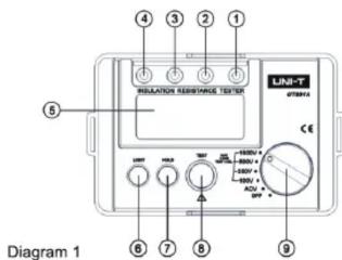
IV. Tester's Structure (See Diagram 1)
- EARTH : Insulation resistance input jack.
- G: Negative voltage input jack.
- V: positive voltage input jack.
- LINE: Insulation resistance input jack(high voltage output)
-
LCD screen
-
Backlight button
-
Data-hold button
- Insulation resistance test button
- Functional knob
V. Functions of Keys and Knobs
- HOLD: data hold;
- LIGHT: turn on or off the backlight source;
- TEST: turn on or off high voltage test;
- Test AC voltage when function knob points to ACV;
- Test DC voltage when function knob points to DCV;
- Test insulation resistance when the function knob points to 100V/250V/500V/1000V (select the desired output voltage).
VI. Voltage Measurement (See Diagram 2)
To measure AC voltage, do the following:
(1) Insert the red test lead into the "V" input port and the black test lead into the "G" input port.
(2) Place the function knob in the ACV function position to test AC voltage.

Caution
- Do not input AC voltage over 750Vrms. It is possible to display a higher voltage but it may cause damage to the instrument or electric shock.
● After all the testing operations, disconnect the test leads and the circuit under test, and remove the test leads from the instrument input jack.
● In case the battery cover is opened, do not conduct any test.
VII. Insulation Resistance Measurement (See Diagram 3)
Caution
a. When measuring insulation resistance, please strictly place the two test probes separately. Do not mix them up.
b. Neither short circuit the two test probes under high voltage output state nor measure insulation resistance after high voltage outputs.
c. In case the battery cover is opened, do not conduct any test.

Diagram 3
1. Turn the function knob to select one of test voltages 100V/250V/500V/1000V.
(1) Before testing insulation resistance, the circuit under test must be completely discharged and completely isolated from power supply circuit.
(2) Insert the red test wire into the "LINE" input port and the black test wire into the "EARTH" input port.
(3) Connect the red and black alligator clip to the circuit under test. The voltage is output from the LINE port.
2. Continuous Measurement
After function knob is set to one of test voltages 100V/250V/500V/1000V, press the TEST key, the instrument will be self-locked to measure continuously. The test voltage will be output and TEST button will light up. With the measurement finished, press TEST button to unlock and stop the measurement.
Caution
● Make sure the tested circuit is de-energized before measurement. Do not measure the insulation of any energized equipment or wire.
● After the measurement is completed, do not touch the circuit by your hand. The capacitance stored in the circuit can cause electric shock.
- Do not touch test wires when they are disconnected from tested circuit, wait until the test voltage is completely discharged.
● In case the battery cover is opened, do not conduct any test.
VIII. Battery Replacement (See Diagram 4)
| Low Voltage Symbol | Battery Voltage |
| 7V or less |
Please follow these steps to replace batteries:
(1) In order to avoid the risk of electric shock, firstly turn off the power source before replacing the battery (i.e. the function knob points at OFF) and remove the test wires.
(2) Unscrew the screws on the cover of battery compartment and remove the battery compartment. Replace six batteries.
(3) After the batteries are replaced, ensure to fasten the screws.
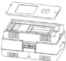
Diagram 4
Caution
- Please do not mix old and new batteries up.
- Please note battery's polarity when installing batteries.
Danger
● In case the battery cover is opened, do not conduct any test.
IX. Maintenance
Clean the casing:
- Clean the surface by a piece of moist soft cloth or sponge with clean water.
- To avoid any damage to the instrument, do not submerge it into water.
- When the instrument is wet, please dry it before storing.
- When there is need to calibrate or repair the instrument, please have it serviced by professional personnel or designated service center.
*END*
The manual information is subject to changes without prior notice.
UNI-T®
UNI-TREND TECHNOLOGY (CHINA) CO., LTD.
No6, Gong Ye Bei 1st Road,
Songshan Lake National High-Tech Industrial
Development Zone, Dongguan City,
Guangdong Province, China
Tel: (86-769) 8572 3888
http://www.uni-trend.com
- UT501A
- OVERVIEW
- SAFETY INFORMATION
- DANGER
- WARNING
- CAUTION
- TESTER'S STRUCTURE (SEE DIAGRAM 1)
- FUNCTIONS OF KEYS AND KNOBS
- VOLTAGE MEASUREMENT (SEE DIAGRAM 2)
- INSULATION RESISTANCE MEASUREMENT (SEE DIAGRAM 3)
- TURN THE FUNCTION KNOB TO SELECT ONE OF TEST VOLTAGES 100V/250V/500V/1000V
- CONTINUOUS MEASUREMENT
- BATTERY REPLACEMENT (SEE DIAGRAM 4)
- MAINTENANCE
- END
- UNI-T®
- UNI-TREND TECHNOLOGY (CHINA) CO., LTD
Marque : Uni-T
Modèle : UT501A
Catégorie : équipements de mesure