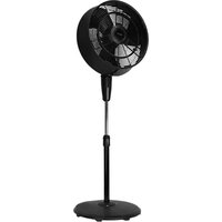
1VAFP18M - Ventilateur VisionAir - Notice d'utilisation et mode d'emploi gratuit
Retrouvez gratuitement la notice de l'appareil 1VAFP18M VisionAir au format PDF.


| Marque | VisionAir |
| Modèle | 1VAFP18M |
| Type de produit | Ventilateur sur pied |
| Dimensions (H x L x P) | 1350 x 450 x 420 mm |
| Poids net | 5,2 kg |
| Diamètre des pales | 40 cm (16 pouces) |
| Alimentation | 220-240 V ~ 50 Hz |
| Puissance nominale | 60 W |
| Vitesses | 3 vitesses (faible, moyen, fort) |
| Oscillation | Oui, automatique 90° |
| Inclinaison | Manuelle réglable |
| Hauteur réglable | Oui, avec tige télescopique |
| Grille de protection | Grille métallique amovible |
| Niveau sonore max | 55 dB(A) |
| Matériau des pales | ABS |
| Couleur | Blanc et gris |
| Longueur du câble | 1,5 m |
| Fonction de mise en veille | Non |
| Fonction de minuterie | Oui, jusqu'à 4 heures |
| Télécommande | Oui, incluse |
| Entretien et nettoyage | Débrancher avant nettoyage ; utiliser un chiffon humide ; ne pas immerger |
| Sécurité | Arrêt automatique en cas de basculement (non spécifié) |
| Pièces détachées disponibles | Pales, grille, moteur, télécommande |
| Réparabilité | Indice de réparabilité estimé 6/10 |
FOIRE AUX QUESTIONS - 1VAFP18M VisionAir
Questions des utilisateurs sur 1VAFP18M VisionAir
0 question sur cet appareil. Repondez a celles que vous connaissez ou posez la votre.
Poser une nouvelle question sur cet appareil
Téléchargez la notice de votre Ventilateur au format PDF gratuitement ! Retrouvez votre notice 1VAFP18M - VisionAir et reprennez votre appareil électronique en main. Sur cette page sont publiés tous les documents nécessaires à l'utilisation de votre appareil 1VAFP18M de la marque VisionAir.
MODE D'EMPLOI 1VAFP18M VisionAir
OWNER'S MANUAL
18" OUTDOOR MISTING FAN

MODEL 1VAFP18M
CONTENTS
RULES FOR SAFETY OPERATION....3
USER SERVICING INSTRUCTIONS .... 4
PART NAMES 4
PREPARATION 4
ASSEMBLY INSTRUCTIONS....5
OPERATING INSTRUCTION 6
GFCI OPERATION....6
CLEANING AND MAINTENANCE INSTRUCTIONS....6
TROUBLE SHOOTING....7
IMPORTANT NOTE:
Read the manual carefully. Make sure to save this manual for future reference. Illustrations in this manual are for explanatory purposes only, your actual product may look slightly different.

WARNING: Cancer www.P65Warnings.ca.gov
RULES FOR SAFETY OPERATION
- Fan should be used under rated voltage.
- Connect power after the fan is fully assembled.
- Never insert fingers, pencils, or any other object through the guard when fan is running.
- Unplug from outlet when: not in use, when moving fan from one location to another, before putting on or taking off parts, and before cleaning.
- Disconnect fan when removing grilles for cleaning.
- Be sure fan is on a stable surface when operating to avoid overturning.
- Do not operate any fan with a damaged cord or plug. Discard fan or return to an authorized service facility for examination and/or repair.
- Do not run cord under carpeting. Do not cover cord with throw rugs, runners, or similar coverings. do not route cord under furniture or appliances. Arrange cord away from traffic area and where it will not be tripped over.
- Press the TEST button (then RESET button) every month to assure proper operation.

WARNING
-
To reduce the risk of fire or electric shock, do not use this fan with any solid state speed control device.
-
This product must be grounded. If it should malfunction or break down, grounding provides a path of least resistance for electric current to reduce the risk of electric shock. This product is equipped with a cord having an equipment-grounding conductor and a grounding plug. Plug into an appropriate outlet that is properly installed and grounded in accordance with all local codes and ordinances.
-
This fan is provided with a ground fault circuit interrupter (GFCI) built into the power supply cord. This device provides additional protection from the risk of electric shock. Should replacement of the plug or cord become necessary, use only identical replacement parts that include GFCI protection.
-
Do not leave the fan running unattended.
-
This product employs overload protection (fuse). A blown fuse indicates an overload or short-circuit situation. If the fuse blows, unplug the product from the outlet. Replace the fuse as per the user servicing instructions (follow product marking for proper fuse rating) and check the product. If the replacement fuse blows, a short-circuit may be present and the product should be discarded or returned to an authorized service facility for examination and/or repair.
-
Risk of fire. Do not replace attachment plug. Contains a safety device (fuse,) that should not be removed. Discard product if the attachment plug is damaged.
USER SERVICING INSTRUCTIONS
a) Grasp plug and remove from the receptacle or other outlet device. Do not unplug by pulling on cord.
b) Open fuse cover. Slide open fuse access cover on top of attachment plug towards blades.
c) Remove fuse carefully. Insert the tip of your tool into fuse slot (close with the terminal), then prize the fuse gradually and slowly, but not overexert. If you feel tight, you can try it at several times and prize the fuse little by little. When one side of the fuse has been prized, then you can get the fuse out entirely.
d) Risk of fire. Replace fuse only with 5 Amp, 125 Volt fuse.
e) Close fuse cover. Slide closed the fuse access cover on top of attachment plug.
f) Risk of fire. Do not replace attachment plug. Contains a safety device (fuse) that should not be removed. Discard product if the attachment plug is damaged.

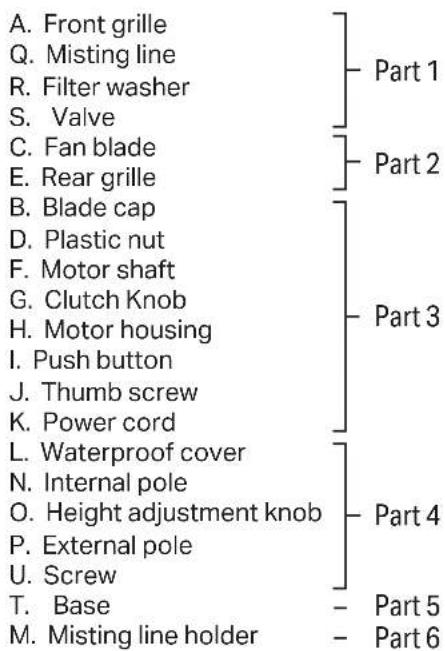
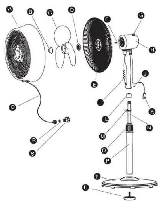
PARTS NAME
PREPARATION
Before beginning assembly of product, Please have screwdriver ready to use. Make sure all parts are present and compare parts with package contents list and diagram above. If any part is missing or damaged, do not attempt to assemble the product. Contact customer service for replacement parts.
ASSEMBLY INSTRUCTIONS
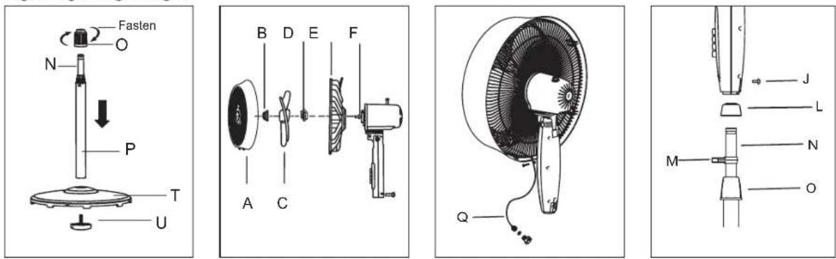
Step 1. Fan Base Assembly (Fig. 1)
- Unscrew the Screw (U) from the external Pole (P) and attach the external Pole (P) to the Base (T) by tightening the Screw(U).
- Remove the height adjustment Knob (O) by unscrewing it counterclockwise.
- Use your finger to pull out the internal Pole(N), slide height adjustment Knob (O) over internal Pole (N). Fasten it to external Pole (P) by turning the knob while holding the pole. Make sure the Knob (O) is tightly fastened.
Step 2. Fan Head Assembly (Fig. 2)
- Remove the blade Cap (B) by turning clockwise. Remove the plastic Nut (D) by turning counter clockwise.
- Position the rear Grille(E) over the motor Shaft(F), make certain the handle is at the top and the one notch in the rear of rear Grille(E) cover fit over the three prong on the motor Housing(G).
- Secure rear Grille(E) by turning the plastic Nut(D) clockwise and tightening firmly.
- Slide the fan Blade(C), with the hollow interior of the blade facing toward rear Grille(E), onto motor Shaft(F).
- Secure Fan Blade(C) onto motor Shaft(F) by turning the blade Cap (B) counterclockwise until it firmly in place.
- Loosen the bolt on the bottom of the Front Grille(A) and mount the Front Grille(A) with the logo right side up to the Rear Grille (E) by snapping both together firmly. Ensure all snaps around the Front Grille(A) are secure on the Rear Grille (E).
- Tighten the bolt on the bottom of the Front Grille(A).
Step 3. Final Assembly (Fig. 4)
- Loosen the thumb Screw (J) by turning it counter clockwise.
- Always keep the water proof Cover(L) match with the height adjustable Knob (O) when adjusting the internal Pole(N).
- Insert internal Pole(N) into the neck joint and tighten by turning thumb Screw(J) clockwise. Make sure it is tight enough to support the fan head.
- Attach the Misting Line Holder(M) onto the Internal Pole(N).
- Secure the Misting Line(Q) to the clip under the Front Grille(A) and the Misting Line Holder(M).
Fig. 1 Fig. 2 Fig. 3 Fig. 4
OPERATING INSTRUCTION
- Place the fan on a level surface. Plug the grounding type attachment plug into a standard 120V AC 3-Prong wall outlet.
- Attach the Valve(S) onto a standard outdoor hose. Turn your water on at the spigot and use the lever on the Valve(S) to turn water on and off. (if water flow is weak, double check the spigot is completely open.)
- To turn oscillation mode on, push the Clutch Knob (G). Pull the Clutch Knob (G) up to turn oscillation off.
- To adjust the air flow upward or downward, simply tilt the fan head with hand and move to desired angle.
- Control speed by pushing the desired button: 0 - OFF, 1 - low, 2 - medium, 3 - high
- The height of the fan can be adjusted by loosening the height adjustment Knob(O) and carefully adjusting the Internal Pole(N). the fan and re-tightening Height adjustment Knob(O). Always ensure the waterproof Cover(L) covers the Height adjustable Knob(O) after adjusting the Internal Pole(N).
GFCI OPERATION
The GFCI in the power supply cord of this fan has 2 buttons "TEST" and "RESET". If you wish to see if the GFCI circuit is functioning properly press the "TEST" button. The fan will immediately shut off as if the GFCI has been activated and the window between the button will change to black. This lets you know the GFCI circuit has been activated. Press the "RESET" button and the fan can be turned on again and the window between the buttons will show orange. This indicates the GFCI circuit has not been activated and the fan should operate normally.
CLEANING AND MAINTENANCE INSTRUCTIONS
The fan requires minimal maintenance. Do not attempt to fix it yourself; instead, refer it to qualified service personnel if servicing is needed.
- Before cleaning and assembling, unplug the machine from outlet.
- To ensure adequate air circulation to the motor, keep the vents at the rear of the motor housing free from dust, fluff, or any debris. Use a vacuum cleaner to clean these vents only after unplugging the fan. Do not disassemble the fan to remove dust, fluff, or any debris.
- Wipe the exterior parts with a soft cloth soaked in mild detergent, rinse with clean water, and air dry. Avoid using any abrasive detergents or solvents to prevent scratching the surface. Do not use gasoline, thinner, or any harsh chemicals as a cleaner.
NOTE: Never allow water or any other liquid to enter the motor housing or interior parts.
Misting Nozzle Maintenance:
- Use a pair of needle-nose pliers to gently twist each nozzle counterclockwise to remove them.
- Once removed, soak the nozzles in white vinegar for 2 hours.
- After soaking, rinse each nozzle with water and then place them back into the front fan grill.
- Twist the nozzles clockwise until they are securely in place. Avoid over-tightening them.
TROUBLE SHOOTING
1. Problem
Misting features sputters or does not mist at all.
Solution
- Ensure your outside water faucet is turned all the way on.
- Check the fan's valve lever and make sure it set open.
- Check water hose for kinks or buckles.
- The valves on the fan may be clogged. Follow the instructions in the "Misting Nozzle Maintenance" section above.
2. Problem
Fan will not run.
Solution
- Ensure the fan is plugged in.
- Check the GFCI on the fan's plug. If the window is black the GFCI has been tripped and needs to be reset.
- Press the "RESET" button on the plug. If the GFCI window is orange then the circuit is active and does not need to be reset.
3. Problem
Fan will not oscillate.
Solution
- Ensure the oscillation knob on the fan is pressed in.
4. Problem
GFCI continues to activate.
Solution
- Try using a different power outlet.
For your records, staple your sales receipt to this manual and record the following:
Date of Purchase:
Place of Purchase: ____
NOTE: Proof of purchase is required for all warranty claims.
NOTE: As a result of continual improvements, the design and specifications of the product within may differ slightly to the unit illustrated on the packaging.

4560 West 160th Street Cleveland, OH 44135
833-950-1185 | support@visionairproducts.com | www.visionairproducts.com

- OWNER'S MANUAL
- 18" OUTDOOR MISTING FAN
- CONTENTS
- IMPORTANT NOTE
- RULES FOR SAFETY OPERATION
- WARNING
- USER SERVICING INSTRUCTIONS
- PARTS NAME
- PREPARATION
- ASSEMBLY INSTRUCTIONS
- STEP 1. FAN BASE ASSEMBLY (FIG. 1)
- STEP 2. FAN HEAD ASSEMBLY (FIG. 2)
- STEP 3. FINAL ASSEMBLY (FIG. 4)
- OPERATING INSTRUCTION
- GFCI OPERATION
- CLEANING AND MAINTENANCE INSTRUCTIONS
- MISTING NOZZLE MAINTENANCE
- TROUBLE SHOOTING
- PROBLEM
- SOLUTION
Marque : VisionAir
Modèle : 1VAFP18M
Catégorie : Ventilateur