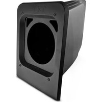
SLG-RSUB10 - Enceinte audio DS18 - Notice d'utilisation et mode d'emploi gratuit
Retrouvez gratuitement la notice de l'appareil SLG-RSUB10 DS18 au format PDF.


| Type de produit | Subwoofer pour système audio |
| Marque | DS18 |
| Modèle | SLG-RSUB10 |
| Diamètre du haut-parleur | 10 pouces (25 cm) |
| Impédance nominale | 4 ohms |
| Puissance nominale (RMS) | 250 watts |
| Puissance maximale (crête) | 500 watts |
| Réponse en fréquence | 30 Hz - 300 Hz |
| Sensibilité | 88 dB (1W/1m) |
| Matériau de la membrane | Polypropylène renforcé |
| Type d'aimant | Ferrite |
| Utilisation recommandée | Caisson de graves pour autoradio |
| Dimensions (Ø x H) | 260 mm x 150 mm |
| Poids | 3,5 kg |
| Alimentation | 12 V (système électrique véhicule) |
| Entretien et nettoyage | Dépoussiérer avec un chiffon doux ; éviter l'humidité |
| Sécurité | Ne pas exposer à l'eau ; respecter la puissance nominale |
| Pièces détachées et réparabilité | Disponibles via service après-vente DS18 |
| Informations générales | Conçu pour une utilisation en intérieur de véhicule |
FOIRE AUX QUESTIONS - SLG-RSUB10 DS18
Questions des utilisateurs sur SLG-RSUB10 DS18
0 question sur cet appareil. Repondez a celles que vous connaissez ou posez la votre.
Poser une nouvelle question sur cet appareil
Téléchargez la notice de votre Enceinte audio au format PDF gratuitement ! Retrouvez votre notice SLG-RSUB10 - DS18 et reprennez votre appareil électronique en main. Sur cette page sont publiés tous les documents nécessaires à l'utilisation de votre appareil SLG-RSUB10 de la marque DS18.
MODE D'EMPLOI SLG-RSUB10 DS18
DS18®
HYDRO
OWNER'S MANUAL
MANUAL DEL USUARIO
SLG-RSUB10
POLARIS SLINGSHOT 10" REAR STORAGE COMPARTMENT SUBWOOFER ENCLOSURE
CAJA DE SUBWOOFER DE 10" PARA EL
COMPARTIMIENTO TRASERO DEL POLARIS SLINGSHOT


POLARIS SLINGSHOT 10" REAR STORAGE COMPARTMENT SUBWOOFER ENCLOSURE
CAJA DE SUBWOOFER DE 10" PARA EL COMPARTIMIENTO TRASERO DEL POLARIS SLINGSHOT
INTRODUCTION
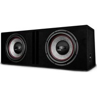
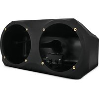
If you're looking to maximize sound in your Polaris Slingshot, you may consider adding this durable Polyethylene 10" Subwoofer Enclosure by DS18. This enclosure allows you to mount one 10" subwoofer using the rear storage compartment to give you the bass that your stereo system deserves. This enclosure comes in black textured finish to match the factory's look. Easy to Install using supplied bolts and brackets directly into place.
FEATURES
- Fits any 10" ds18 subwoofer (not included)
- easy to install - all hardware and wiring included.
- Ofc tinned 12ga wiring for more power handling and durability.
- 6 core 3.2 ft / 1m input wires for rgb lighting and speaker.
■ Fits slingshot models from 2015 or later. - Works for both driver and/or passenger side storage compartment.
- Coated metal bracket for better resistance to the elements.
- Black oem finish.
- Durable (pe) waterproof enclosure with uv protection.
- 0.75ft3 / 21l ported / vented enclosure type.
- Damping material for better subwoofer performance.
WHAT'S IN THE BOX
■ Empty Subwoofer Enclosure
- Face Plate
- Mounting Brackets
■ 6 x M6x16mm Screws and Washers
- 4 x M6x40mm Screws and Washers
- 6 x M6 Clip-On Nut
- Speaker Wiring
INTRODUCCIÓN
Si está buscando maximizar el sonido en su Polaris Slingshot, puede considerar agregar esta caja para Subwoofer de 10" de polietileno duradero de DS18. Esta caja le permite montar un subwoofer de 10" usando el compartimiento de almacenamiento trasero para brindarle el bajo que su sistema estereo merece. Esta caja viene en un acabado texturizado negro para que coincida con el aspecto de fábrica. Fácil de instalar utilizando los pernos y soportes suministrados directamente en su lugar.
CARACTERÍSTICAS
- Se adapta a cualquier subwoofer DS18 de 10". (NXL-10SUB/BK recomendado)
- Fácil de instalar con todo el hardware y cableado incluidos.
- Cableado OFC estañado 12Ga para mayor manejo de potencia y durabilidad.
- Cables de entrada de 6 núcleos de 1 m/3,2 pies para iluminación RGB y altavoz.
- Se adapta a todos los SlingShots de 2015 en adelante.
- Funciona tanto para el compartimento de almacenamiento del lado del conductor como del pasajero.
- Soporte de metal revestido para una mejor resistencia a los elementos.
- Acabado OEM negro.
- Caja resistente al agua (PE) duradera con protección UV.
- Tipo de caja con puerto / ventilado de 0.75ft3 / 21L.
- Material de amortiguación para un mayor rendimiento de los subwoofers.
QUÉ HAY EN LA CAJA
- Caja de subwoofer vacía
- placa frontal
■ Soportes de montaje
■ 6 tornillos y arandelas M6x16mm
■ 4 tornillos y arandelas M6x40 mm
■ 6 tuercas con clip M6.
■ Cableado de altavoz
INSTALLATION
Starts by moving the seats all away forward to get easy access to this area, it is optional if you want to remove the seats for running wires or easy installation on both driver and passenger side of the vehicle. (Picture 1)
INSTALACIÓN
Comience moviendo todos los asientos hacia adelante para tener fácil acceso a esta área, es opcional si desea quitar los asientos para pasar cables o facilitar la instalación en el lado del conductor y del pasajero del vehículo. (Imagen 1)

Remove the Passenger rear deck hump using a T25 TORX socket to extract the (2) screws on front bottom of the piece and pull it to the front, (Picture 2)
Retire la joroba de la plataforma trasera del Pasajero usando una punta TORX T25 para extraer los (2) tornillos en la parte inferior delantera de la pieza y tire de ella hacia el frente, (Imagen 2)

INSTALLATION
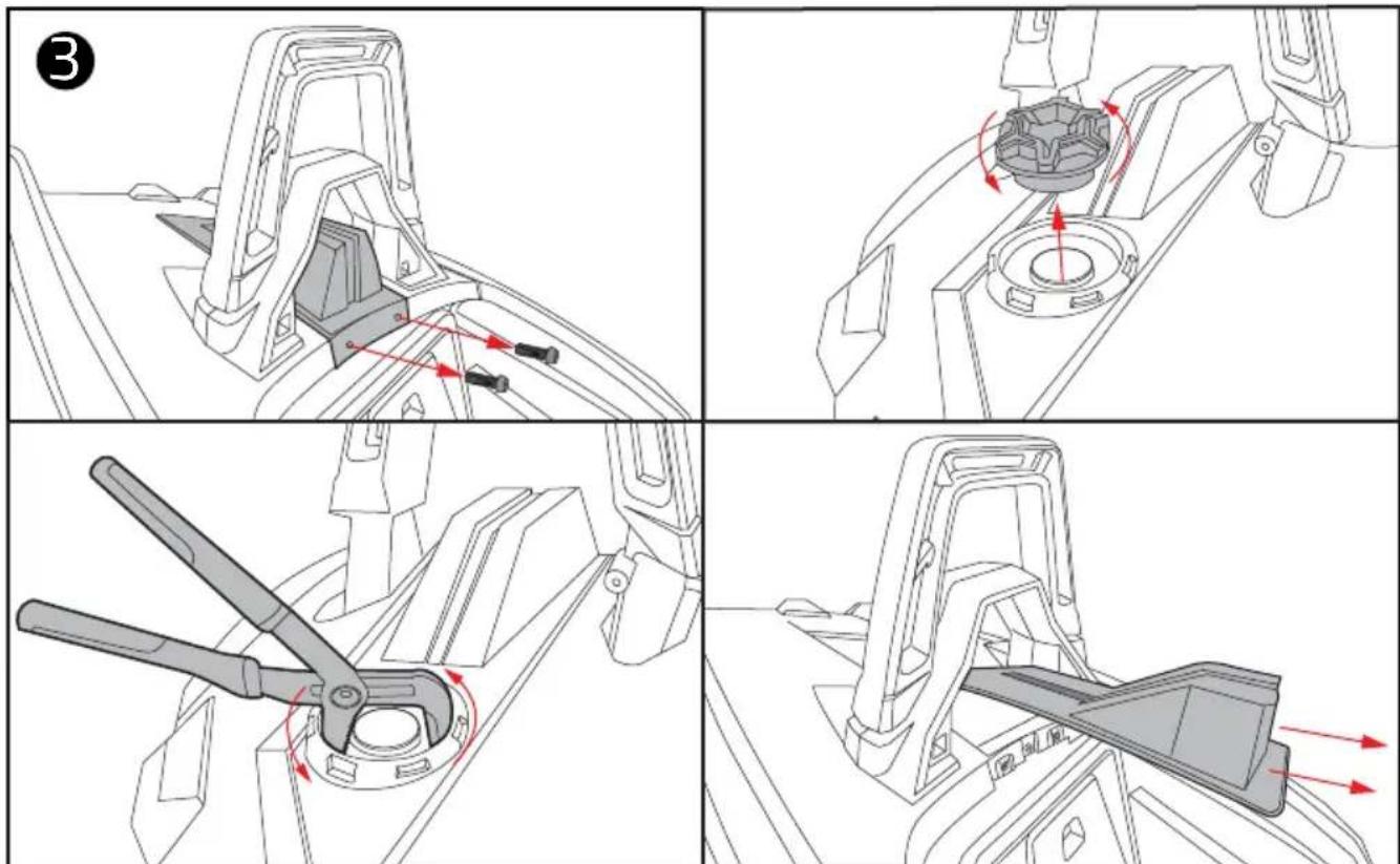
Remove the Driver rear deck hump using a T25 TORX socket to extract the (2) screws on front bottom of the piece, then remove the gas cap and using an oversized pliers, un-screw the Ring-Nut that holds the gas tube in place, after this you can pull out the piece. (Picture 3)
INSTALACIÓN
Retire la joroba de la plataforma trasera del conductor con una punta TORX T25 para extraer los (2) tornillos en la parte inferior delantera de la pieza, luego retire la tapa de la gasolina y, con unos alicates de gran tamaño, desatornille la tuerca anular que sujeta el tubo de gasolina en su lugar, después de esto puedes sacar la pieza. (Imagen 3)
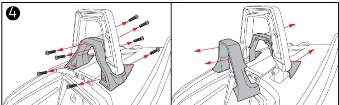
Remove both driver and passenger side rear hoop accent using a T40 TORX socket to extract the (2) screws on bottom of the piece and a T25 TORX to extract the (2) screws on top of the piece and pull it to the font, then using the T40 TORX to extract the (2) screws in the back of the piece and pull it to the back. (Picture 4)
Quite el acento del aro trasero del lado del conductor y del pasajero usando una punta TORX T40 para extraer los (2) tornillos en la parte inferior de la pieza y un TORX T25 para extraer los (2) tornillos en la parte superior de la pieza y jálelo hacia la fuente, luego utilizando el T40 TORX para extraer los (2) tornillos en la parte posterior de la pieza y tirar de ella hacia atrás. (Imagen 4)
INSTALLATION
Remove screws that were located underneath the head covers once the humps are removed.
(Picture 5)
INSTALACIÓN
Retire los tornillos que estaban ubicados debajo de las cubiertas de la cabeza una vez que se quitaron las jorobas. (Imagen 5)

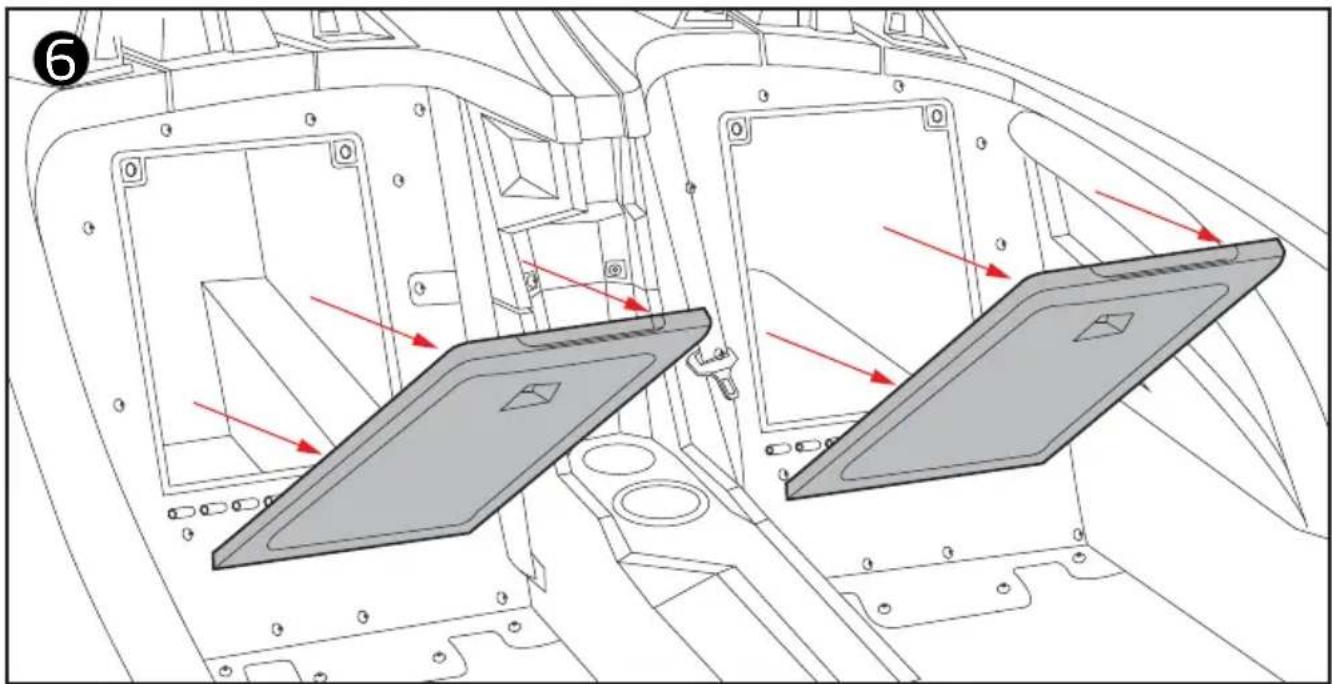
Remove the doors that cover both driver and passenger side rear storage compartment.
(Picture 6)
Retire las puertas que cubren el compartimiento de almacenamiento trasero del lado del conductor y del pasajero. (Imagen 6)
INSTALLATION
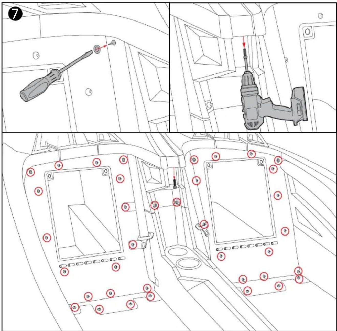
Remove all T40 TORX screws and (2) push clips that are located on back panel. (Picture 7)
INSTALACIÓN
Retire todos los tornillos TORX T40 y los (2) clips de presión que se encuentran en el panel posterior. (Imagen 7)
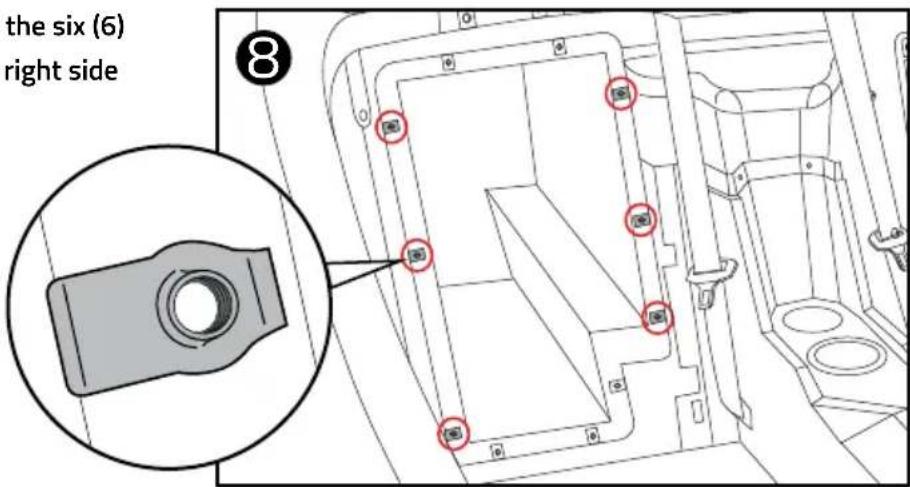
For 2017 and newer models, use the six (6) supplied clip nuts on the left and right side to mount the cabinet. (Picture 8)
Para los modelos de 2017 en adelante, use las seis (6) tuercas con clip suministradas en el lado izquierdo y derecho para montar el gabinete.(Imagen 8)
INSTALLATION
This kit needs an aftermarket amp pre-installed with the speaker wires in this location, only after this step can you connect the speakers using the aftermarket amp's speaker wire and RGB LED wires (optional) of the LED module (LED -BTC not included). (Picture 9)
INSTALACIÓN
Este kit necesita un amplificador del mercado de accesorios preinstalado con los cables de los altavoces en esta ubicación, solo después de este paso puede conectar los altavoces usando el cable del altavoz del amplificador del mercado de accesorios y los cables LED RGB (opcional) del módulo LED (LED -BTC no incluido). (Imagen 9)
9

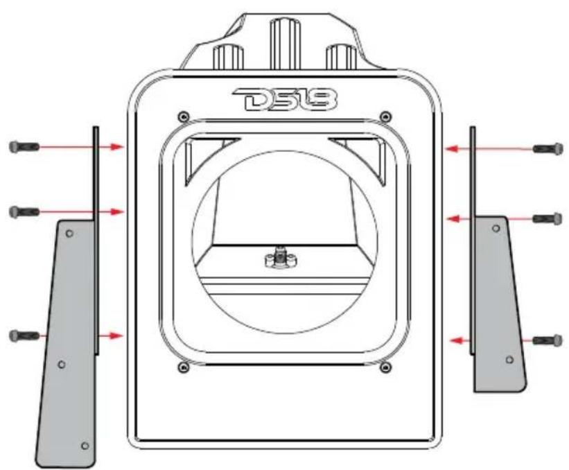
If the enclosure does not have the Subwoofer and the brackets installed already, go ahead, and put it in place and secure it using the supplied bolts and washers, be careful not to overtighten or the hole may be damaged and not properly secure the parts. (Picture 10)
Si la caja no tiene el Subwoofer y los soportes instalados, siga adelante, colóquelo en su lugar y asegúrelo con los pernos y arandelas suministrados, tenga cuidado de no apretar demasiado o el orificio podría dañarse y no asegurar correctamente las piezas. (Imagen 10)
10
INSTALLATION INSTALACIÓN
Grab the top and bottom of the enclosure and slide the Subwoofer box into place in the rear compartment. (Picture 11)
Tome la parte superior e inferior del gabinete y deslice la caja de Subwoofer en su lugar en el compartimiento trasero. (Imagen 11)

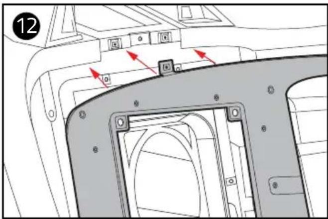
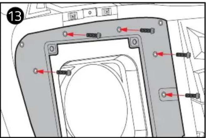
Once finished, re-install the rear panel, and install the factory T40 TORX screws back to secure SLG-RSUB10 enclosure. (Picture 12) (Picture 13)
Una vez que haya terminado, vuelva a instalar el panel posterior e instale los tornillos TORX T40 de fábrica para asegurar la carcasa SLG-RSUB10. (Imagen12) (Imagen13)
Attach the face plate using the T30 TORX screws. (Picture 14)
Fije la placa frontal con los tornillos TORX T30. (Imagen 14)
Re-install everything back in order from the rear hump and hoop accent in the same way that was pulled out. This concludes the installation of the SLG-RSUB10 and it is ready to enjoy your new sound system upgrade!

Vuelva a instalar todo en orden desde la joroba trasera y el acento del aro de la misma manera que lo sacó.
¡Esto concluye la instalación del SLG-RSUB10 y está listo para disfrutar de su nueva actualización del sistema de sonido!

MEASUREMENTS / MEDIDAS:

MEASUREMENTS / MEDIDAS:
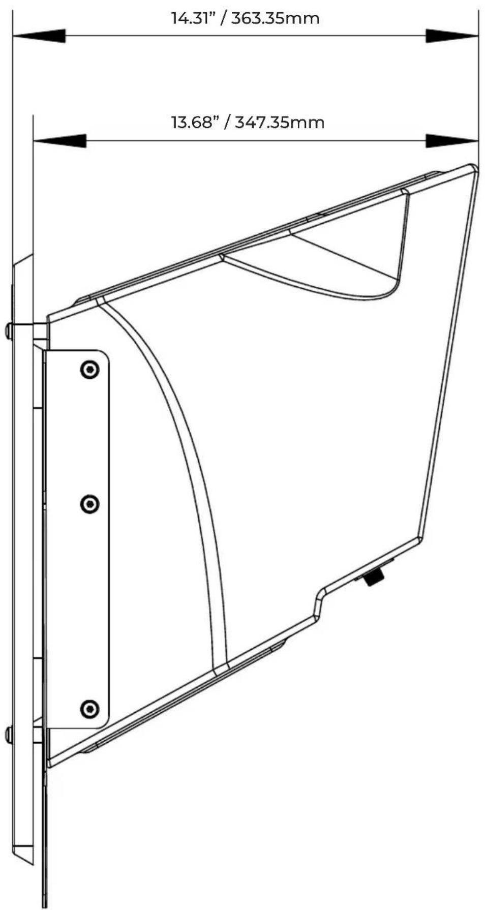
MEASUREMENTS / MEDIDAS:

WARRANTY
Please visit our website DS18.com for more information on our warranty policy.
We reserve the right to change products and specifications at any time without notice. Images may or may not included optional equipment.

WARNING:
Cancer and Reproductive Harm.
www.P65Warning.ca.gov
GARANTÍA
Visita nuestra página web DS18.com para obtener más información sobre nuestra garantía.
Nos reservamos el derecho de cambiar productos y especificaciones en cualquier momento sin previo aviso. Las imágenes pueden incluir o no equipo opcional.

ADVERTENCIA:
Cáncer y Daño Reproductivo.
www.P65Warning.ca.gov
FOR MORE INFORMATION
PLEASE VISIT
DS18.COM
- DS18®
- OWNER'S MANUAL
- MANUAL DEL USUARIO
- SLG-RSUB10
- POLARIS SLINGSHOT 10" REAR STORAGE COMPARTMENT SUBWOOFER ENCLOSURE
- INTRODUCTION
- FEATURES
- WHAT'S IN THE BOX
- INTRODUCCIÓN
- CARACTERÍSTICAS
- QUÉ HAY EN LA CAJA
- INSTALLATION
- INSTALACIÓN
- INSTALLATION INSTALACIÓN
- WARRANTY
- WARNING
- GARANTÍA
- ADVERTENCIA
- FOR MORE INFORMATION
- PLEASE VISIT
- DS18.COM
Marque : DS18
Modèle : SLG-RSUB10
Catégorie : Enceinte audio