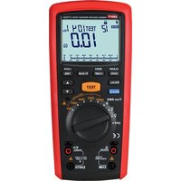
UT505A - équipements de mesure Uni-T - Notice d'utilisation et mode d'emploi gratuit
Retrouvez gratuitement la notice de l'appareil UT505A Uni-T au format PDF.


| Type de produit | Testeur de résistance d'isolement (mégohmmètre) |
| Marque | Uni-T |
| Modèle | UT505A |
| Dimensions (approx.) | 200 x 100 x 50 mm |
| Poids (approx.) | 500 g |
| Alimentation | Piles 1,5 V AA (x8) ou batterie rechargeable 9 V (selon version) |
| Fonctions principales | Mesure de résistance d'isolement jusqu'à 2000 MΩ, test de continuité, mesure de tension AC/DC jusqu'à 600 V |
| Tension de test | 500 V, 1000 V, 2500 V (sel gamme) |
| Affichage | Écran LCD rétroéclairé |
| Entretien et nettoyage | Nettoyer avec un chiffon sec et non abrasif. Ne pas utiliser de solvants ou de produits chimiques. |
| Sécurité | Catégorie de mesure CAT III 600 V, double isolation |
| Pièces détachées et réparabilité | Fils de test, pinces crocodiles, fusible de protection. Réparation uniquement par un technicien qualifié. |
| Informations générales | Appareil de mesure portable pour tests d'isolement électrique. Livré avec sacoche de transport, cordons de test, manuel d'utilisation. |
FOIRE AUX QUESTIONS - UT505A Uni-T
Questions des utilisateurs sur UT505A Uni-T
0 question sur cet appareil. Repondez a celles que vous connaissez ou posez la votre.
Poser une nouvelle question sur cet appareil
Téléchargez la notice de votre équipements de mesure au format PDF gratuitement ! Retrouvez votre notice UT505A - Uni-T et reprennez votre appareil électronique en main. Sur cette page sont publiés tous les documents nécessaires à l'utilisation de votre appareil UT505A de la marque Uni-T.
MODE D'EMPLOI UT505A Uni-T

UT505A
UNI-T
UT505A OPERATING MANUAL
UNI-T
OPERATING MANUAL
Contents
I. OVERVIEW 1
II. UNPACKING INSPECTION 1
III. SAFETY CODES 2
IV. ELECTRICAL SYMBOL 3
V. EXTERNAL STRUCTURE 4 XL LCD SCREEN
XI. EUD SCREEN VII. KEY FUNCTION
-
SAVE/CLEAR
-
RECALL 5
-
HOLD/BACKLIGHT 5
-
COMP 6
-
PI/DAR 6
-
LOCK/TIME 6
-
TEST 6
-
UP AND DOWN REGULATION 5
VIII. DESCRIPTION OF MEASUREMENT OPERATION 7
-
MEASUREMENT OF AC VOLTAGE 7
-
DC VOLTAGE MEASUREMENT 8
-
MEASUREMENT OF LOW-RESISTANCE 8
-
MEASUREMENT OF INSULATION RESISTANCE 10
-
USE OF COMPARISON FUNCTION
-
USE OF DATA STORAGE FUNCTION
-
USE OF DATA STORAGE FUNCTION
-
POWER GEAR
-
AUTOMATIC POWER-OFF FUNCTION 1
IX. TECHNICAL INDICATOR....12
-
GENERAL SPECIFICATION....12
-
ELECTRICAL SPECIFICATIONS 12
-
TECHNICAL INDICATOR 13
X. MAINTENANCE AND UPKEEP 15
-
GENERAL MAINTENANCE 15
-
INSTALLATION OR REPLACEMENT OF BATTERY/FUSE 15
UNI-T
UT505A OPERATING MANUAL
UNI-T
OPERATING MANUAL
I. Overview
UT505A is a digital insulation test meter featuring brand-new design, large-scale integrated circuit and digit circuit, capable of measuring such parameters as the insulation resistance, DC voltage and AC voltage; it is designed with complete functions, higher accuracy, stable performance and convenient operability. Therefore, it can be used for measuring the insulation resistance of electric equipments and insulation materials such as the transformers, motors, cables, switches and electric appliances, and for the service, maintenance, test and verification of various electrical equipments. UT505A is the ideal choice for you.
II. Unpacking inspection
Unpack and take out the insulation test instrument, please check carefully if the following attachment are complete or intact, if any lack or damage were found, please contact with your supplier.
| UTS05A bars instrument | 1 |
| Test line (Red + black) | 2 |
| Alligator clip (Red + black) | 2 |
| Test probe (Red + black) | 2 |
| Uni-trend warranty certificate (in both Chinese and English) | 1 |
| 1.5V AA alkaline battery | 6 |
| User Manual | 1 |
| Black neutral bag | 1 |
| Optional Components: | |
| One remote-controlled test pen | 1 |
III. Safety Codes
The instrument is designed and produced strictly in accordance with the safety requirements for GB4793 electronic measuring instrument and IEC61010-1 safety standard. It meets the double insulation over-voltage standard CAT IV 600V and pollution degree II. If fail to use the instrument under the relevant operation instructions, the protection provided shall be weakened or lost.
- Check the instrument and test pen before using to guard against any damage or abnormal phenomenon. If any abnormal condition were found: bare test pen, damaged chassis, no display or random display in LCD, please do not use it. It is forbidden to use the instrument without rear cap or rear cap not in place, or otherwise there will be electric shocking.
- Damaged test pen should be replaced with the one of same type or electric specification.
- Do not contact the bare wire and connector, unused input terminal or the circuit being measured when the instrument is in operation.
- Be careful in measuring voltage higher than DC 42V or AC 30V and keep finger within the scope of test pen finger protection position to guard against electric shocking.
- Set the function range switch at the maximum range position if the scope of measured value couldn't be defined.
- Refrain from applying between terminals or the terminals and grounding the voltage or current over the rating value labeled on the instrument.
- Function switches shall be set at the correct position in measurement. Before converting function switches, connection between the table pen measured circuits shall be broken off and gear conversion in measurement shall be prohibited to guard against damage to the instrument.
- Before measuring on-line resistance, the power of circuits to be measured shall be powered off and all capacitors shall release out all residues of electric charges.
UNI-T
UT505A OPERATING MANUAL
- Refrain from storing or using the instrument in the explosive and flammable environment with high temperature, high humidity and strong electromagnetic field.
- Refrain from changing the internal wiring in the instrument to guard against damage to the instrument and danger.
- When LCD display shows the icon *■*, it is required to replace the battery in time to ensure the measurement accuracy.
Note: do not measure the insulation resistance when the battery voltage is less than 7.8V indicated by low-voltage symbol; replace the battery immediately when the battery is lower than 7.2V indicated by the flashing low-voltage symbol.
- Power off immediately after measurement. Take out battery when the clamp ammeter will not be in use for a long time.
IV. Electrical symbol (See Table 1)
| Warning & caution safety label | |
| Double insulation | |
| DC (Direct Current) | |
| AC (Alternative Current) | |
| Low battery | |
| Dangerous high voltage! | |
| Buzzing on-off | |
| Earthing | |
| Comply with European Union standards |
3
UNI-T
OPERATING MANUAL
V. External structure (See Figure 1)
LCD display area: displaying the measured data and functional symbols.
Functional key area: selecting basic functions. Rotary switch: selecting the measurement function gear.
Measurement port area:
- Positive end of low-resistance jack;
- Negative end of low-resistance jack;
- Positive end of input jack for AC/DC voltage measurement and insulation resistance measurement;
- Negative end of input jack for AC/DC voltage measurement and insulation resistance measurement;
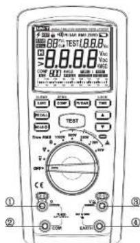
Figure 1
UNI-T
UT505A OPERATING MANUAL
XI. LCD screen (See Figure 2)

Figure 2
![graph TD A["1 CLEAR"] --> B["2 RECALL"] C["3 HOLD 0"] --> B D["4 ZERO"] --> E["5 PIDAR"] F["6 LOCK"] --> G["7 TEST"] H["8 ▲"] --> G I["9 TIME"] --> G J["10 SAVE"] --> B K["11 COMP"] --> E L["12 KEY"] --> G M["13 错误"] --> G N["14 错误"] --> G O["15 错误"] --> G P["16 错误"] --> G Q["17 错误"] --> G R["18 错误"…](/content/2026/07/1417521/images/567035c72e8b60193df97c700ed90d55764117d11572c44762dde723adeb0ebe.jpg)
VII. Key function (See Figure 3)
- SAVE/CLEAR
With a short press, select SAVE (Save) function to save the current measured data; Under the RECALL interface, with a long press on the button "SAVE/CLEAR" about 3s, all saved data will be cleared when "CLR" occurs on the display screen.
- RECALL
With a short press on the button, the previously saved measured values are retrieved, and exit the function after another press.
- HOLD/
With a short press on the button, enter the reading hold measurement mode, and after another press, exit the mode.
With a long press on the button, the backlight is turned on and remains on constantly, after another long press, it will be turned off.
5
UNI-T
OPERATING MANUAL
- COMP
The button is used to define the pass/fail comparison value for insulation measurement. "PASS" will be displayed when the measured insulation value is larger than the set value, and "NG" will be displayed when the former value is less than the later one; press the button to select the required comparison value, such as 100K, 200K,300K,400K,500K 1M, 2M, 3M, 4M, 5M, 10M, 20M, 30M, 40M, 50M, 100M, 200M, 300M, 400M, 500M, 1G, 2G, 3G, 4G, 5G and 10G.
- PI/DAR
The button is used to configure the testing instrument to conduct insulation polarization index or absorption ratio test. With a short press on the button, the screen displays DAR (absorption ratio), time ratio (TIME2:TIME1) is simultaneously set as 1min: 15s; with the second short press, the time ratio (TIME2:TIME1) for insulation polarization index is set as 1min: 30s; with the third short press, the screen displays PI (polarization index) and currently the time ratio (TIME2:TIME1) is set as 10min: 60s; and with the fourth short press, the PI/DAR (polarization index/absorption ratio) test function is canceled. The test can be conducted by pressing the test button after selecting a required time ratio.
- LOCK/TIME
It is a multiplex button. With a short press on the button, you can set the test time, while pressing down TEST (test) button, it begins timing until the expiration of your set time, accompanied by a buzzer sound and red indicator going out; the available time for timing measurement includes: 15S, 30S, 60S, 75S, 90S and 10min. With a long press on LOCK, the lock test function is activated, and after another long press, the lock is lifted.
- TEST
When rotary switch is located at INSULATION (insulation), the insulation test is activated. The test instrument provides high-voltage and measures the insulation resistance. When the rotary switch is located at Ω (ohm) gear, the low-resistance test is activated.
- Up and down regulation
Function 1: used to set the insulation measurement voltage output.
Function 2: used to save the up and down retrieval while recalling the measured data.
UNI-T
UT505A OPERATING MANUAL
VIII. Description of measurement operation
- Measurement of AC voltage (See Figure 4)
① Insert red test pen in "≈▼" jack (red hole) and black
test pen in "EARTH" jack (black hole).
② Push the rotating switch to the gear "v" and connect test pen in parallel with the power source or to both ends of the load to be measured.
③ Directly read the measured voltage value from display.
④ To save the measured voltage value during measurement just push the button "SAVE".
Note: - Do not input the voltage higher than 1000V since higher voltage may cause damage to the instrument.
● Take special care to avoid electric shocking while measuring high voltage and if necessary, wear the insulation gloves.
● After completing measurement operation, disconnect the test pen from the circuits to be measured. - When the measured voltage is higher than the safety voltage 42V/DC, the meter display screen will display high voltage warning prompt “ 5/8 ± ; when the input overvoltage is higher than 1000V, the meter will automatically output high voltage warning prompt “ 5/8 ± , which would flash on the top left corner of screen for warning.
7
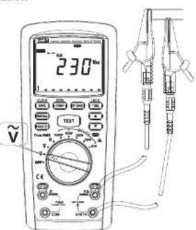
Figure 4
UNI-T®
OPERATING MANUAL
- DC voltage measurement (See Figure 5)
① Insert red test pen in "▽" jack (red hole) and black test pen in "EARTH" jack (black hole).
② Push the rotating switch to the gear "▽" and connect test pen in parallel with the power source or to both ends of the load to be measured.
③ Directly read the measured voltage value from display. ④ To save the measured voltage value during measurement, just push the button "SAVE".
Note:
● Do not input the voltage higher than 1000V since higher voltage may cause damage to the instrument.
● Take special care to avoid electric shocking while measuring
high voltage and if necessary, wear the insulation gloves. ● After completing measurement operation, disconnect the test pen from the circuits to be measured. - When the measured voltage is higher than the safety voltage 60V/DC, the meter display screen will display high voltage warning prompt "S"±; when the input overvoltage is higher than 1000V, the meter will automatically output high voltage warning prompt "S"±, which would flash on the top left corner of screen for warning.
- Measurement of low-resistance (See Figure 6) ① Insert the red test pen in "Ω" jack (red hole), with another end connected with the alligator clip; and
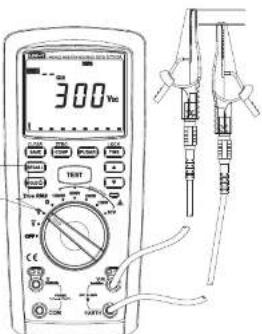
Figure 5
UNI-T
UT505A OPERATING MANUAL
Insert the black test pen in COM jack (black hole),
② Push the rotating switch to the gear "Ω" and connect
test pen in parallel with the circuit to be measured.
③ Press down "TEST", after waiting for current measured value on the display.
④ To save the current measured value during measurement,
just push the button "SAVE".
To ensure the measurement accuracy, the test pen of the instrument should be returned to zero prior to measurement so as to remove the error caused by the test pen; detailed operation procedures are as follows: short circuit the aligator clip of test pens, after pressing down "TEST", the screen displays the resistance value less than 2.000, and after another long press on "COMP" 3s, the symbol "ZERO" appears on the right upper corner of screen and the screen displays "0.000", indicating successful to return zero.
Note:
- It is required to ensure prior to measurement that the object to be measured is electrically neutral, or otherwise resulting in inaccurate measurement.
- Prior to test, the instrument will judge if the object to be measured is electrified higher than 2V, if so, LCD displays high-voltage symbol and measurement is forbidden.
- When the resistance exceeds the maximum display range, the instrument screen would display the symbol > and the maximum resistance of the current range.
9

Figure 6
UNI-T®
OPERATING MANUAL
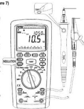
- Measurement of insulation resistance (See Figure 7)
① Insert red test pen in "×V" jack (red hole) and black test pen in "EARTH" jack (black hole).
pen in EARTH JACK (black hole). ②. Relate the rotary switch to INSU
(3) Rotate the rotary switch to INCUATION (Insulation resistance area), select the required test voltage and connect the test pen in parallel with the circuit to be measured.
③ After pressing down "TEST" (test), view the current resistance value from the main display area on the display and the test voltage in the auxiliary display area. Meanwhile, the screen will flash and display the high-voltage warning symbol "5" when the test voltage is higher than 30V, then you can press down the test button.
④ After pressing down "TEST" button, LCD screen will blink displaying high-voltage warning symbol "S" in case of high-voltage output, in addition, the red alarm light beside the alarm symbol on the case is turned on
⑤ To save the current measured value during measurement, just push the button "SAVE"
Note: - It is required to ensure prior to measurement that the object to be measured is electrically neutral, or otherwise resulting in inaccurate measurement.
- Prior to test, the instrument will judge if the object to be measured is electrified higher than 25V, if so, LCD displays high-voltage symbol and measurement is forbidden.
- When the resistance exceeds the maximum display range, the instrument screen would display the symbol > and the maximum resistance of the current range.
10
UNI-T
UT505A OPERATING MANUAL
- Polarization index or insulation absorption ratio (See Figure 7)
The wiring measurement method is quite similar to the insulation resistance measurement, just set it as polarization index or absorption ratio;
With a short press on the button, the screen displays DAR (absorption ratio), time ratio (TIME2:TIME1) is simultaneously set as 1min: 15s; with the second short press, the time ratio (TIME2:TIME1) for insulation polarization index is set as 1min: 30s; with the third short press, the screen displays PI (polarization index) and currently the time ratio (TIME2:TIME1) is set as 10min: 60s; and with the fourth short press, the PIDAR (polarization index/absorption ratio) test function is canceled. The test can be conducted by pressing the test button after selecting a required time ratio.
- Use of comparison function (See Figure 7)
The wiring measurement method is quite similar to the insulation resistance measurement, just need to set it as the comparison function. "PASS" will be displayed when the measured insulation value is larger than the set value, and 'NG' will be displayed when the former value is less than the later one; press the button to select the required comparison value, such as 100K, 200K,300K,400K,500K 1M, 2M, 3M, 4M, 5M, 10M, 20M, 30M, 40M, 50M, 100M, 200M, 300M 400M, 500M, 1G, 2G, 3G, 4G, 5G and 10G. Comparison value.
① Save the measured value: with a short press on "SAVE", save the current measured value, meanwhile the saved number on the display screen increases by one group, with a maximum of 99 groups:
② Recall the measured value: enter the data recall mode by pressing "RECALL", then view the saved data by means of the "Up/Down" button.
③ Clear the saved measured data: press "RECALL"± to enter the data recall mode, after a long press on "SAVE/CLEAR"about 3s, the screen would display"CLR"±, indicating all saved data being cleared.
- Power gear
To power off, turn the rotary switch to "OFF".
- Automatic power-off function
There will be blanking display on the screen and the instrument enters micro-power consumption state if not turning rotary switch of pressing the button within 3 min. If need to awake the instrument, just turn the rotary switch to "OFF"± and then to another measurement gear.
11
UNI-T®
OPERATING MANUAL
IX. Technical indicator
- General specification
● Display: LCD display, with maximum reading being 9999;
● Low battery alarm: See Table 1
● Overranging indication: * >20.0 GΩ* within the scope of insulation resistance;
● Automatic range function
- Unit display: displaying the function and electric quantity unit symbol;
● Working condition: 0°C \~ 40°C/ relative humidity 85% or less;
● Storage condition: -20°C \~ 60°C/ relative humidity 90% or less;
● Overall dimensions: mm (225L)X mm (103W)X mm(59D): Current consumption: about 500mA (in case of maximum output 1000V) (about 10mA at ordinary times);
- It is designed and produced in strict compliance with safety standard IEC61010, overvoltage standard
(CAT IV 600V) and pollution grade II.
● Battery: AA 1.5V ×6
- Battery life: a group of new alkaline batteries may last for more than 800 times of insulation resistance test when positioning the selector switch in insulation resistance test position. (Test 1 MΩ at 1000V for 5S with an interval period of 25S); a group of new alkaline batteries may last for more than 230 times of low resistance test when positioning the selector switch in low resistance test position. (Test 1 Ω for 5S with an interval period of 25S):
● Automatic release of voltage;
● Backlight allows for operation in the dark environment.
● Red warning light.
IP Level: IP 40
- Accessory: test wire, alligator clip, alkaline battery 1.5V (AA) × 6, user manual and a carrying case;
● Weight: 0.7kg (inclusive of battery).
● Compliance Standards: EN61010-1:2010; EN61010-2-030:2010; EN61010-2-033:2012; EN61557-1:2007; EN61557-2:2007; EN61557-4:2007; EN61326-1:2013; EN61326-2-2:2013
UNI-T
UT505A OPERATING MANUAL
2. Electrical specifications
-
Limit of error: ± (a% reading + word count), with calibrating interval being one year;
● Environmental temperature: 23±5℃
● Environmental humidity: 45\~75%RH;
● Temperature coefficient: 0.1° (accuracy) /°C; -
Technical indicator (See Figure 2)
| Output voltage | 50V stepping 10% | 50%-120% | 0%~+10% | 250V | 50V output range: 25V-60V |
| 100V stepping 10% | 100V output range:50V-120V | ||||
| 250V stepping 10% | 250V output range:125V-300V | ||||
| 500V stepping 10% | 500V output range:250V-600V | ||||
| 1000V stepping 10% | 1000V output range:500V-1200V | ||||
| Rated current | 1mA | 0%~+10% | 250V | 50V: load resistance 50KΩ | |
| 1mA | 100V: load resistance 100KΩ | ||||
| 1mA | 250V:load resistance 250KΩ | ||||
| 1mA | 500V:load resistance 500KΩ | ||||
| 1mA | 1000V:load resistance 1MΩ | ||||
| Short-circuit current | Less than 2mA | High-voltage output terminal is short circuited with EARTH terminal. | |||
UNI-T®
OPERATING MANUAL
| Measurement of insulation resistance | (50V)0.01M~19.99M20.0M~50.0M | 0.01MQ0.1MQ | 0.01MQ~50.0MQ:3%+5 | 25V | 1. Short-circuit current less than 2mA;2. Range of measurement is described below: 50V:0.01MQ-50.0MQ, there will be buzzing alarm output in case of less than 1MQ;100V: 0.01MQ-100.0MQ, there will be buzzing alarm output in case of less than 1MQ;250V: 0.01M-200.0MQ, there will be buzzing alarm output in case of less than 4MQ;500V: 0.01MQ-500 MQ, there will be buzzing alarm output in case of less than 4MQ;1000V: 0.0MQ- 10.0 MQ, there will be buzzing alarm output in case of less than 4MQ. |
| (100V)0.01M~19.99M20.0M~100.0M | 1MQ0.01GΩ | 0.01MQ~100.0MQ:3%+5 | |||
| (250V)0.01M~19.99M20.0M~200.0M | 0.01MQ0.1MQ | 0.01MQ~200.0MQ:1.5%+5 | |||
| (500V)0.01M~19.99M20.0M~199.9M200M~500M | 0.01MQ0.1MQ1MQ | 0.01MQ~500MQ1.5%+5 | |||
| (1000V)0.01M~19.99M20.0M~199.9M200M~2000M2.0GΩ~20.0GΩ | 0.01MQ1MQ0.1GΩ | 0.01MQ~200.0MQ:1.5%+5200MQ~200.0MQ:1.5%+52.0GΩ~10.0GΩ:10%+310.0GΩ~20.0GΩ:20%+10 | |||
| Measurement of low resistance | 20.00KΩ | 0.01Ω | ±1.5%+3 | 2VAC/DC | Open-circuit voltage is about 5.0V;Short-circuit current is higher than 200mA; |
| Voltage measurement | 600.0V AC | 0.1V | ± (2%+3) | 600V AC | 1. Input impedance: 10 MQ2. Minimum measured voltage: 0.1V;3. Frequency: DC/50Hz~400Hz |
| 600.0V DC | 0.1V | ± (2%+3) | 600V DC |
UNI-T
UT505A OPERATING MANUAL
UNI-T
OPERATING MANUAL
X. Maintenance and upkeep
Warning: prior to open the upper cover of instrument, be sure the power is shut down and test pen is away from input port and circuit-under-test.
1. General maintenance
● Clean the surface with wet cloth or sponge.
- Do not immerse the instrument in water to prevent damage.
- For the wet instrument, dry it prior to storage. - The clamp ammeter, if required, should be calibrated or serviced by qualified professional serviceman or designated maintenance department.
2. Installation or replacement of battery/fuse (See Figure 8)
6 1.5V(AA) batteries, as shown in Figure 8, provide power for the product. Please install or replace batteries as follows:
① Turn the rotary switch to OFF (shut down) and take off the test wire from the terminal.
② Remove three screws from the battery cover with the standard cross screwdriver, take off the cover and
take out the batteries, then install the new batteries as per the indication of polarity.
③ It is required to install batteries of the same model. Do not install the improper batteries.
① Take out the damaged fuse as per the methods specified in Figure 8, and replace them with the fuse of
the same specification (specification: 500mA/800V).
⑤ After installing new battery, put the battery cover in place and screw on three screws.

Figure 8
UNI-T
UNI-T
UT505A OPERATING MANUAL
OPERATING MANUAL
The operating instruction is subject to change without any further notice.
17
UNI-T.
UNI-TREND TECHNOLOGY (CHINA) CO., LTD.
No6, Gong Ye Bei 1st Road,
Songshan Lake National High-Tech Industrial
Development Zone, Dongguan City,
Guangdong Province, China
Tel (86-769) 8572 3888
http://www.uni-trend.com
18
- UNI-T
- CONTENTS
- OVERVIEW
- UNPACKING INSPECTION
- SAFETY CODES
- UT505A OPERATING MANUAL
- EXTERNAL STRUCTURE (SEE FIGURE 1)
- KEY FUNCTION (SEE FIGURE 3)
- DESCRIPTION OF MEASUREMENT OPERATION
- UNI-T®
- OPERATING MANUAL
- TECHNICAL INDICATOR
- ELECTRICAL SPECIFICATIONS
- MAINTENANCE AND UPKEEP
- GENERAL MAINTENANCE
- INSTALLATION OR REPLACEMENT OF BATTERY/FUSE (SEE FIGURE 8)
Marque : Uni-T
Modèle : UT505A
Catégorie : équipements de mesure