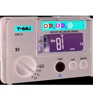
UT582 - équipements de mesure Uni-T - Notice d'utilisation et mode d'emploi gratuit
Retrouvez gratuitement la notice de l'appareil UT582 Uni-T au format PDF.


| Type de produit | Multimètre numérique |
| Marque | Uni-T |
| Modèle | UT582 |
| Dimensions | Environ 150 x 70 x 30 mm |
| Poids | Environ 200 g (avec pile) |
| Alimentation | Pile 9 V type 6F22 |
| Affichage | Écran LCD rétroéclairé, 4000 points |
| Fonctions principales | Mesure de tension AC/DC, courant AC/DC, résistance, capacité, fréquence, test de diode et de continuité |
| Plage de tension DC | 400 mV / 4 V / 40 V / 400 V / 1000 V |
| Plage de tension AC | 400 mV / 4 V / 40 V / 400 V / 750 V |
| Plage de courant DC | 400 µA / 4000 µA / 40 mA / 400 mA / 10 A |
| Plage de résistance | 400 Ω / 4 kΩ / 40 kΩ / 400 kΩ / 4 MΩ / 40 MΩ |
| Catégorie de sécurité | CAT III 1000 V, CAT IV 600 V |
| Indice de protection | IP20 |
| Entretien et nettoyage | Nettoyer avec un chiffon sec et doux. Ne pas utiliser de solvants. |
| Sécurité | Utiliser les cordons de test appropriés. Respecter les tensions maximales indiquées. |
| Pièces détachées et réparabilité | Pile remplaçable. Fusible de protection accessible. Pour toute réparation, contacter un service agréé. |
| Documents fournis | Notice d'utilisation, cordons de test, pile |
FOIRE AUX QUESTIONS - UT582 Uni-T
Attention : ne pas dépasser les limites de sécurité.
Questions des utilisateurs sur UT582 Uni-T
0 question sur cet appareil. Repondez a celles que vous connaissez ou posez la votre.
Poser une nouvelle question sur cet appareil
Téléchargez la notice de votre équipements de mesure au format PDF gratuitement ! Retrouvez votre notice UT582 - Uni-T et reprennez votre appareil électronique en main. Sur cette page sont publiés tous les documents nécessaires à l'utilisation de votre appareil UT582 de la marque Uni-T.
MODE D'EMPLOI UT582 Uni-T
UT582+
Digital RCD (ELCB) Tester User Manual
I. Safety Warning
This manual contains warning information and safety regulations. Please read them carefully and observe them strictly to ensure the safety of the user and instrument.
Note:
- Please read and understand the contents of the manual before using the instrument.
- Please use the instrument in strict accordance with the test procedure described in the manual.
- Please be sure to understand the safety aspects of the manual in detail
- This instrument must be operated by a trained and qualified technician and used under the conditions specified in the manual.
- Uni-Trend is not responsible for any damage caused by improper use or violation of the safety regulations in the manual.
Safety symbol “⚠️” has three meanings in the manual. Users should pay special attention to the operation for the symbol when reading.
Danger----identifies conditions and actions that are likely to pose serious or fatal hazards.
Warning—identifies conditions and actions that may pose serious or fatal hazards
Caution—identifies conditions and actions that may pose minor injury or damage the instrument.
Danger
- The RCD test function of this instrument is only applicable to single-phase 230V /50Hz (power voltage range: 195\~253V) circuits;
the measuring voltage range of this instrument is 30V\~600V, 45Hz\~65Hz. - Before using the instrument, please check the test lead carefully. If the test lead is cracked and the metal wires are bare, do not use it. Otherwise, serious or fatal hazards are likely to be posed.
- When testing, only under safe conditions can you finger the test lead.
- When testing, do not touch any exposed leads.
- After completing the test, please disconnect the test lead from the power immediately
Warning
- During the test, never open the casing of the instrument because of the dangerous voltage in it. In the event of a malfunction, please refer it to a professional for inspection and repair.
- If there are any anomalies (such as imperfect display, unexpected test value, damaged casing, noise during testing, etc.) of the instrument, please hand it over to a professional for repair before use.
- Do not use the instrument if your hands are wet.
Caution
- To ensure safety, please use the certified test lead provided by Uni-Trend. It is forbidden to use other test leads.
- Do not expose the instrument to harsh environments such as the sun, extreme temperatures and humidity.
- Please clean the instrument with a dry cloth. Do not use a damp cloth, abrasive or solvent to clean it.
- If the instrument is wet, dry it before storage.
Warnings:
-
If a possible voltage between the protective conductor and earth will influence the measurements.
-
It needs to test the connection between the neutral point of the distribution system and earth before the test is started. A possible voltage between the N-conductor and the earth may influence the measurements.
- The leakage currents in the circuit following the residual current protection device may influence the measurements.
- When the fault voltage is over 50V, "Uf Hi" will be displayed and the test will stop. The voltage relates to the residual operating current of the protective device.
- The earth electrode resistance of the measuring circuit probe cannot surpass 5Ω.
- The potential fields of other earthing installations may influence the measurement.
- Special conditions in residual current protective devices of a particular shall be taken into consideration.
- Equipment is connected downstream of a residual current protective device may cause a considerable extension of the operating time.
The meaning of the symbols associated with this instrument:
| ⚠️ | Danger, warning or caution | ☐ | Double or reinforced insulation |
| ⊥ | Grounding | CE | Conforms to EU standards |
II. Features
- Intelligent microprocessor chip control: High accuracy, reliability and stability
- RCD Test Wiring Check:
1) When the wiring is correct, the L-PE and L-N symbols on the left side of the LCD are always on.
2) If the power is abnormal or no power, the L-PE and L-N symbols on the left side of the LCD flash simultaneously.
3) If the power socket is not well grounded or not grounded, the L-PE and N-PE symbols on the left side of the LCD flash simultaneously.
4) If the null line of the power socket is not well connected or not connected, the L-N and N-PE symbols on the left side of the LCD flash simultaneously.
5) If the live wire phase and null line phase of the power socket are inversely connected, the L-PE, L-N, and N-PE symbols on the left side of the LCD flash simultaneously.
| Item | Scene | L-PE | L-N | N-PE |
| 1 | If the wiring is correct | on | on | off |
| 2 | If the power is abnormal or no power, | flash | flash | off |
| 3 | If the power socket is not well grounded or not grounded | flash | off | flash |
| 4 | If the null line of the power socket is not well connected or not connected | off | flash | flash |
| 5 | If the live wire phase and null line phase of the power socket are inversely connected | flash | flash | flash |
-
Phase angle selection: The RCD test can be selected to start from a positive (0°) or a negative (180°) half cycle.
-
Contact voltage alarm: The contact voltage can be limited to UL25V or UL50V. When the contact voltage is larger than the selected limit value during the RCD test, the RCD test will be stopped and the LCD will display "Hi" and "Uf".
-
Auto data hold: After RCD test, the measurement results are kept displayed until keystroke or gear switch.
-
Over range indication: When the test value exceeds the maximum or minimum value of the current test range, the LCD will display ">current maximum value" (such as >300ms) or "<current minimum value" (such as <30V).
-
AUTO RAMP test: Test the trip current and trip time simultaneously.
- Battery powered: 1.5V AA alkaline battery (6 pcs). There will be Low voltage indication when the battery voltage is approximate 7.2V.
- Auto Power Off function: The instrument will be power off automatically after no operation for 5 minutes.
- Fuse safeguard
- Double or reinforced Insulation for safe design.
- Backlight function: Press the "LIGHT" key and power on the instrument to turn the backlight on; In the "VOLTS" position, press the "LIGHT" key to turn the backlight on/off.
- L-N voltage measurement: Display L-N input voltage. The display range is 30V\~600V. “----” is displayed when there is no input or the input is extremely small, “<30V” is displayed when the input is less than 30V, and “>600V” is displayed when the input is larger than 600V. Press the “L-N/L-PE” key to switch to L-PE voltage display.
- L-PE voltage measurement: Display L-PE input voltage. The display range is 30V\~600V. “----” is displayed when there is no input or the input is extremely small, “<30V” is displayed when the input is less than 30V, and “>600V” is displayed when the input is larger than 600V. Press the “L-N/L-PE” key to switch to L-N voltage display.
- Frequency measurement: Display the input frequency of the L-PE terminal. In the "VOLTS" position, press the "VOLT/FREQ" key to switch the voltage/frequency display.
III. Technical Specifications
- Measurement Range and Measurement Accuracy (Temperature: 23±5°C; Humidity: 45%\~75% RH; Altitude ≤2000m)
Voltage measurement function:
| Function | Voltage Range | Frequency Range | Display Resolution | Accuracy Error |
| VOLTS | 30V~600V | 45Hz~65Hz | 1V/1Hz | ± 3%rdg ± 3dgt (Frequency display is for reference only) |
RCD test function:
| Function | Voltage (AC) | Trip Current (lAn) | Trip Time (MAX) | Accuracy | |
| × 1/2 | 230V(Tolerance: -15%~+10%) | 10/20/30/100/300/500mA | 2000mS | Trip Current | Trip Time |
| ×1 | 10/20/30/100 /300 mA | 1000mS | Tolerance:-10%~0% | ±2%rdg ±2dgt | |
| ×5 | 500mA | 300mS | Tolerance:0%~+10% | ||
| AUTO RAMP Test | Frequency: 50Hz | 10/20/30mA | 40mS(RAMP increase step 10%) I n from 20%~110%300*10 mS | Tolerance:-10%~+10% | |
| 10/20/30/100/300/500mA | |||||
Factors that might affect the measurement results:
| No. | Designation code | Variable descriptions |
| 1 | A | Intrinsic uncertainty |
| 2 | E1 | Reference position ± 90° |
| 3 | E2 | Voltage supply at the limits stated by the manufacturer |
| 4 | E3 | 0°C and 35°C temperature |
| 5 | E5 | Resistance of the probes within the limits stated by the manufacturer |
| 6 | E8 | 85% to 110% of the nominal system voltage |
- Measurement Range (Function)
| VOLTS | Voltage measurement, 30V~600V, 45Hz~65Hz |
| × 1/2 | Non-tripping test, check RCD sensitivity |
| × 1 | Measure trip time |
| × 5 | Measure fast trip time at IΔn × 5 trip current |
| AUTO RAMP test | Measure trip current |
3. Application Standard:
IEC 61010-1; IEC 61010-2-030; IEC 61010-2-033; IEC 61557-1;
IEC 61557-6; EN 61326-1; EN 61326-2-2
CAT III 600V
Pollution Degree: 2
4. RCD Test Operating Voltage:
230V/50Hz (voltage range: 195\~253V)
5. Working Environment:
Temperature: 0°C\~40°C
Relative humidity: ≤80%RH
Altitude: ≤2000 meter
6. Storage Condition:
Temperature: -20°C\~60°C
Relative humidity: ≤75%RH
7. Product size: 160mmx70.5mmx100mm
- Product weight: About 400g
9. Standard Accessories:
3 terminals test lead (1.5 meter) ----1pc
User manual 1 pc
Shell/strap/cloth bag 1 set
Test lead 1 set
IV. Instrument Appearance and Main Accessory
(See Figure 1, 2, 3)

Figure 1
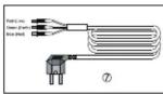
Figure 2

Figure 3
1. LCD
- PHASE/UL key (RCD function) L-N/L-PE key
(voltage measurement function)
-
IΔn key (RCD function) LIGHT key (Backlight function)
-
TEST key (RCD function) VOLT/FREQ key
(voltage measurement function)
5. Function
-
Test ports
-
There terminals test lead
8. Test lead
V. Voltage Measurement
Please use the test leads which meet CAT III 600V, IEC 61010-031:2015 requirement to test the voltage (The maximum voltage which being tested should be less than 600V). Test Lead connection method: Insert the red test lead into L ports and black test lead into N ports of the instrument being measured. (If the voltage is less than 250V, you can also use the 3 terminals of the test lead (but it is not recommend). Test Lead connection method: Insert the three terminals of the test lead into the three corresponding ports of the instrument: Red into L, green into E and blue into N.)
- Turn the dial to the corresponding test gear (VOLTS) of the voltage measurement function and start up the instrument.
- Press the "L-N/L-PE" key to switch to L-N/L-PE voltage display.
- Press the "VOLT/FREQ" key to switch to voltage/frequency display.
VI. RCD Test
1. Test Lead Connection
Insert the three terminals of the test lead into the three corresponding ports of the instrument: Red into L, green into E and blue into N. Turn the dial to the corresponding test gear ( ×1/2 , ×1 , ×5 and AUTO RAMP) of the RCD test function and start up the instrument. Then connect the plug of the test lead to the circuit to be tested (power socket 230V/50Hz).
2. Wiring Check
Check the wiring status by identifying the L-PE, L-N and N-PE symbols. When the wiring is correct, the L-PE and L-N symbols on the left side of the LCD are always on and the N-PE is off. Otherwise, the wiring is incorrect; check and correct the relevant wiring until correct wiring indication is obtained.
Caution: Reverse connection between E and N ports during wiring check may cause RCD to trip. In this case, please check and correct the relevant wiring until the wiring indication is obtained before you proceed to next operation.
Danger
If the wiring is incorrect, do not proceed with the test (press the TEST
key). Otherwise, it very likely causes false test results or other hazards
- Press the "l△n" key to switch so that the trip current (l△n) matches the rated trip current indicated on the RCD (residual current device). The set trip current value will be displayed at the bottom of the LCD.
Default value: IΔn---- 30mA
0 0°
4. Taking RCD Test
1) Set test parameters.
Non-tripping test —×1/2: Maximum trip time up to 2000ms
Tripping test ---- ×1: Maximum trip time up to 1000ms
(except 500mA)
Tripping test —— ×1(500mA): Maximum trip time up to 300ms
Fast tripping test ——×5 (only for 10, 20, 30mA): Maximum trip
time up to 40ms
AUTO RAMP test ---- 20%\~110% of rated trip current (I△n)
Maximum trip time up to 300ms
2) Press the "TEST" key.
Non-tripping test — The RCD should not trip.
Tripping test — The RCD should trip.
×5 fast tripping test — The RCD should trip.
AUTO RAMP test — The RCD should trip; trip time and trip
current should be displayed simultaneously.
3) Press the "PHASE/UL" key to alter the phase and repeat step 2 above to determine the fastest trip time (When the "PHASE/UL" key is pressed, the set value is cyclically switched in the order of UL25V 0° , UL25V 180° , UL50V 180° and UL50V 0° ).
4) Press the "PHASE/UL" key to alter the phase and repeat step 2) again.
5) After completing the test, please disconnect the test lead from the power immediately.
Danger
- Do not touch any exposed metal or leads during the operation of these tests.
- Internal components in the instrument may get hot during testing. If the instrument is operated continuously for a long time, it very likely causes damage to the device or other hazards. Therefore, it is not recommended to use the instrument for a long period of continuous testing on production lines in RCD factories. It is only suitable for sampling precision testing.
- Trip current of 300mA/500mA test (high current tripping test) only can be conducted every five minutes.
VII. Maintenance and Repair
1. Cleaning the Casing
2. Repair
Clean the casing of the instrument gently with a dry cloth. Do not use
alcohol or solvent as it is corrosive to the casing, especially the LCD.
Please prevent the instrument from being wet.
Please contact the after-sales service center or agent of Uni-Trend if the
following issues occur.
A. The casing of the instrument is broken or the components are damaged.
B. LCD displays abnormally.
C. Unexpected test data occur under normal use.
D. The keys do not function normally.
E. Noise occurs during the test.
This instruction manual is subject to change without notice.
UNI-T®
UNI-TREND TECHNOLOGY (CHINA) CO., LTD.
No6, Gong Ye Bei 1st Roa
Songshan Lake National High-Tech Industrial
Development Zone, Dongguan City,
Guangdong Province, China
Tel: (86 769) 8572 3888
http://www.uni-trend.com
http://www.dri-trend.com

- UT582
- DIGITAL RCD (ELCB) TESTER USER MANUAL
- SAFETY WARNING
- NOTE
- DANGER
- WARNING
- CAUTION
- WARNINGS
- FEATURES
- TECHNICAL SPECIFICATIONS
- APPLICATION STANDARD
- RCD TEST OPERATING VOLTAGE
- WORKING ENVIRONMENT
- STORAGE CONDITION
- PRODUCT SIZE: 160MMX70.5MMX100MM
- STANDARD ACCESSORIES
- INSTRUMENT APPEARANCE AND MAIN ACCESSORY
- LCD
- FUNCTION
- TEST LEAD
- VOLTAGE MEASUREMENT
- RCD TEST
- TEST LEAD CONNECTION
- WIRING CHECK
- TAKING RCD TEST
- SET TEST PARAMETERS
- PRESS THE "TEST" KEY
- MAINTENANCE AND REPAIR
- CLEANING THE CASING
- REPAIR
- UNI-T®
- UNI-TREND TECHNOLOGY (CHINA) CO., LTD
- NO6, GONG YE BEI 1ST ROA
Marque : Uni-T
Modèle : UT582
Catégorie : équipements de mesure