
RS-TR337 - Lecteur de cassette TECHNICS - Notice d'utilisation et mode d'emploi gratuit
Retrouvez gratuitement la notice de l'appareil RS-TR337 TECHNICS au format PDF.

| Type de produit | Lecteur/enregistreur de cassettes double plateau |
| Marque | TECHNICS |
| Modèle | RS-TR337 |
| Dimensions (approx.) | 430 x 130 x 300 mm |
| Poids (approx.) | 6 kg |
| Alimentation | Secteur 110-240 V (sélectionnable), 50/60 Hz |
| Réduction de bruit | Dolby NR, HX Pro |
| Fonctions de lecture | Lecture bidirectionnelle, recherche rapide avance/recul, arrêt, pause |
| Fonctions d'enregistrement | Enregistrement bidirectionnel, silence automatique, synchronisation (Synchro Start) |
| Calibration de bande | Calibration automatique (ATC) avec détection de type (Fe, CrO2, Metal) |
| Copie de cassette | Copie de plateau 1 à plateau 2 avec sélection de vitesse (x1, x2) |
| Mode de retournement | Sélectionnable : simple face, continu, auto-reverse |
| Compteurs | Deux compteurs à remise à zéro |
| Entretien et nettoyage | Nettoyer les têtes et galets avec un coton-tige imbibé d'alcool isopropylique. Démagnétiser les têtes périodiquement. |
| Sécurité | Débranchez l'appareil avant tout entretien. N'utilisez pas de nettoyants abrasifs. Utilisez des pièces de rechange spécifiées par le fabricant. |
| Pièces détachées et réparabilité | Les composants marqués d'un symbole de sécurité doivent être remplacés par des pièces d'origine TECHNICS. Consultez un technicien qualifié. |
| Informations générales | Notice complète disponible en PDF sur notice-facile.com. Référez-vous au schéma de principe et à la liste des pièces. |
FOIRE AUX QUESTIONS - RS-TR337 TECHNICS
Questions des utilisateurs sur RS-TR337 TECHNICS
0 question sur cet appareil. Repondez a celles que vous connaissez ou posez la votre.
Poser une nouvelle question sur cet appareil
Téléchargez la notice de votre Lecteur de cassette au format PDF gratuitement ! Retrouvez votre notice RS-TR337 - TECHNICS et reprennez votre appareil électronique en main. Sur cette page sont publiés tous les documents nécessaires à l'utilisation de votre appareil RS-TR337 de la marque TECHNICS.
MODE D'EMPLOI RS-TR337 TECHNICS
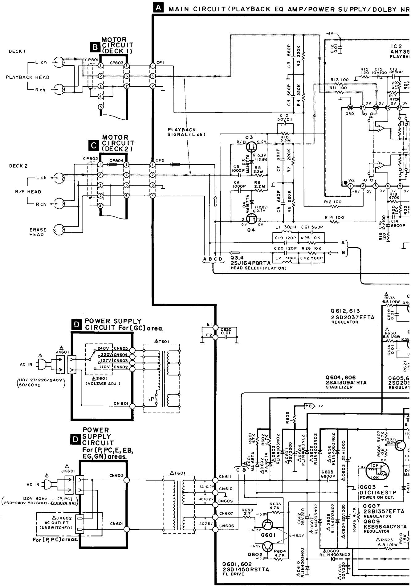
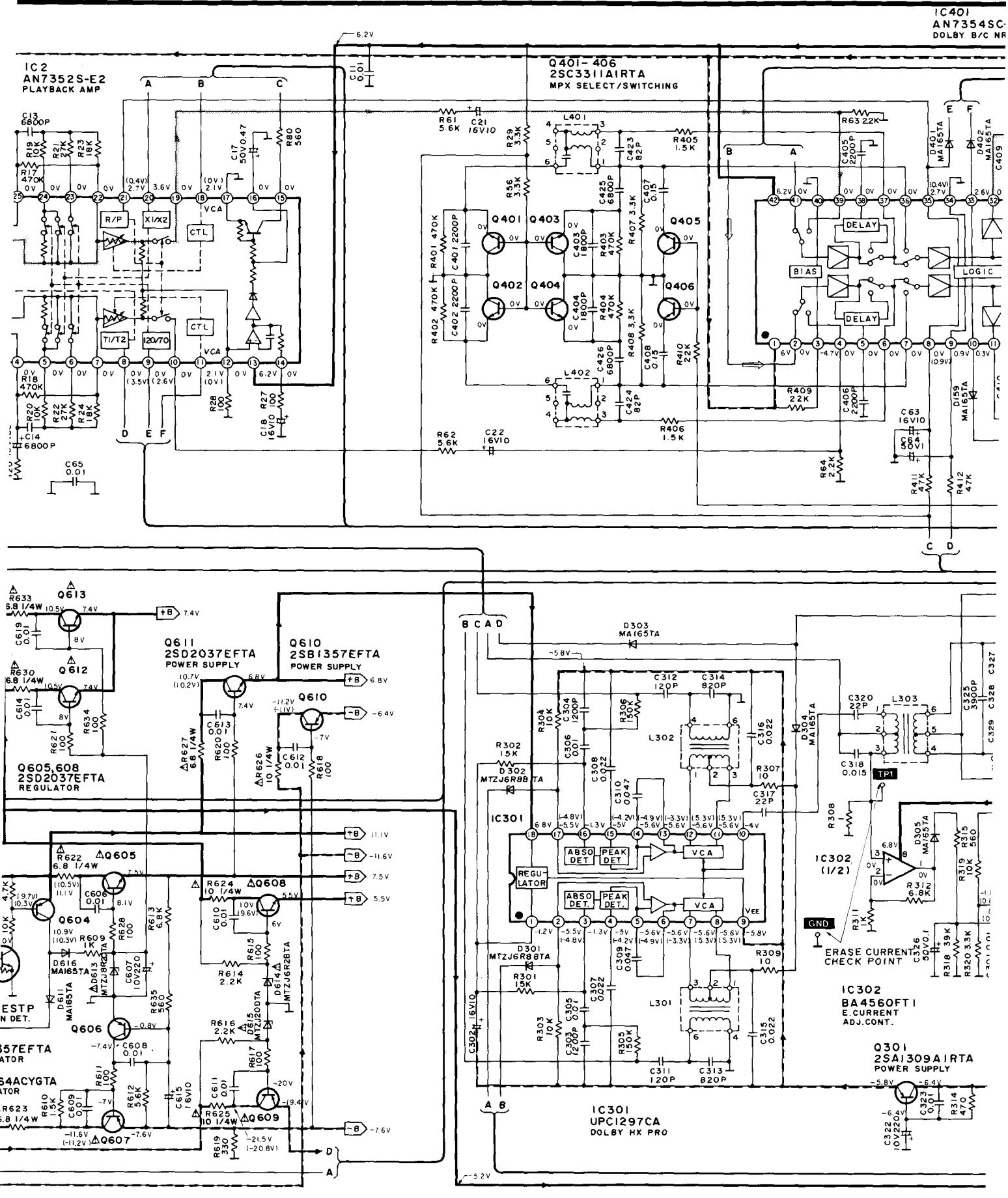
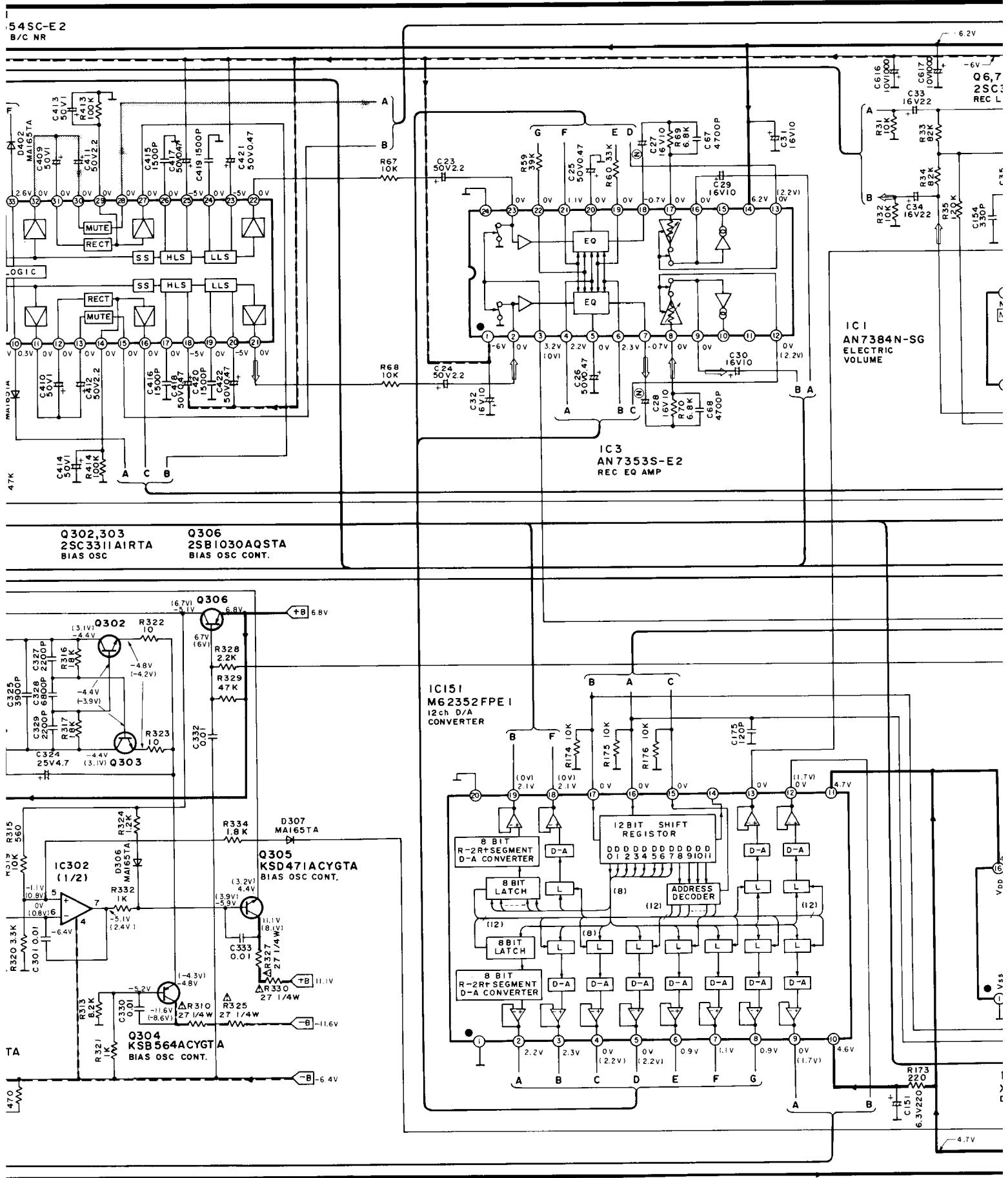
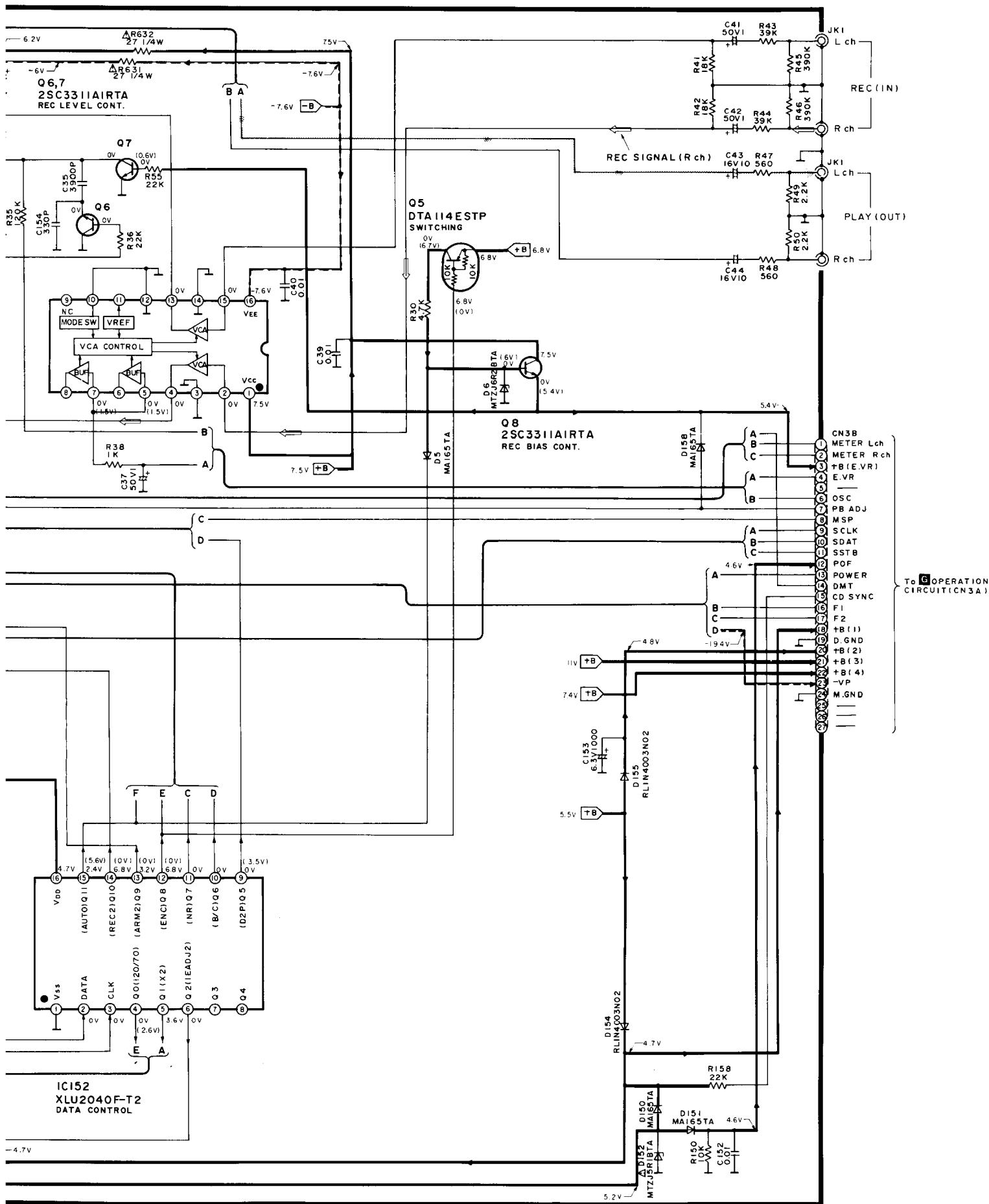
BY NR/HX PRO/BIAS OSC/REC EQ AMP/CONTROL/ELECTRIC VOLUME)
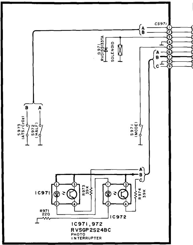
E MECHANISM CIRCUIT (DECKI)
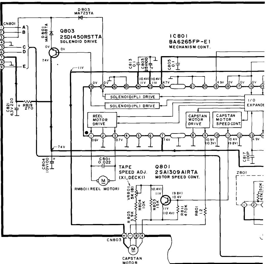
B MOTOR CIRCUIT (DECKI)
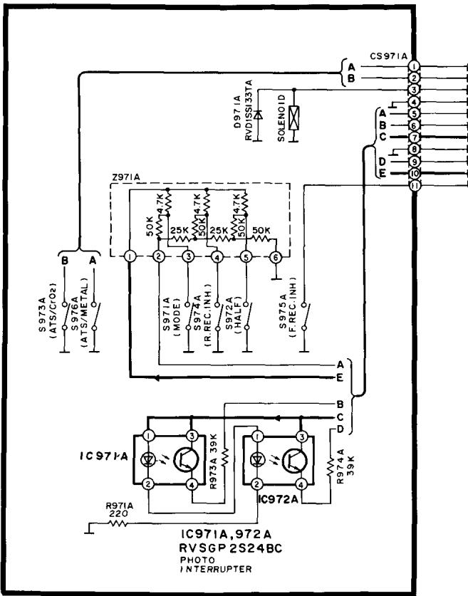
F MECHANISM CIRCUIT (DECK2)
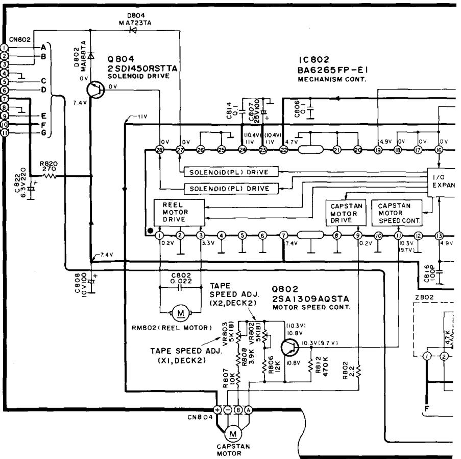
C MOTOR CIRCUIT (DECK2)
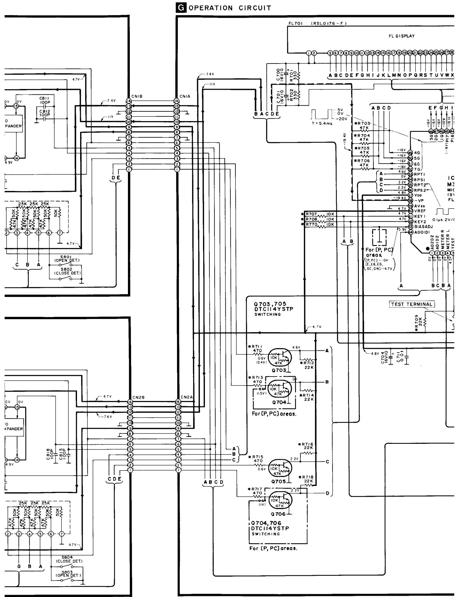
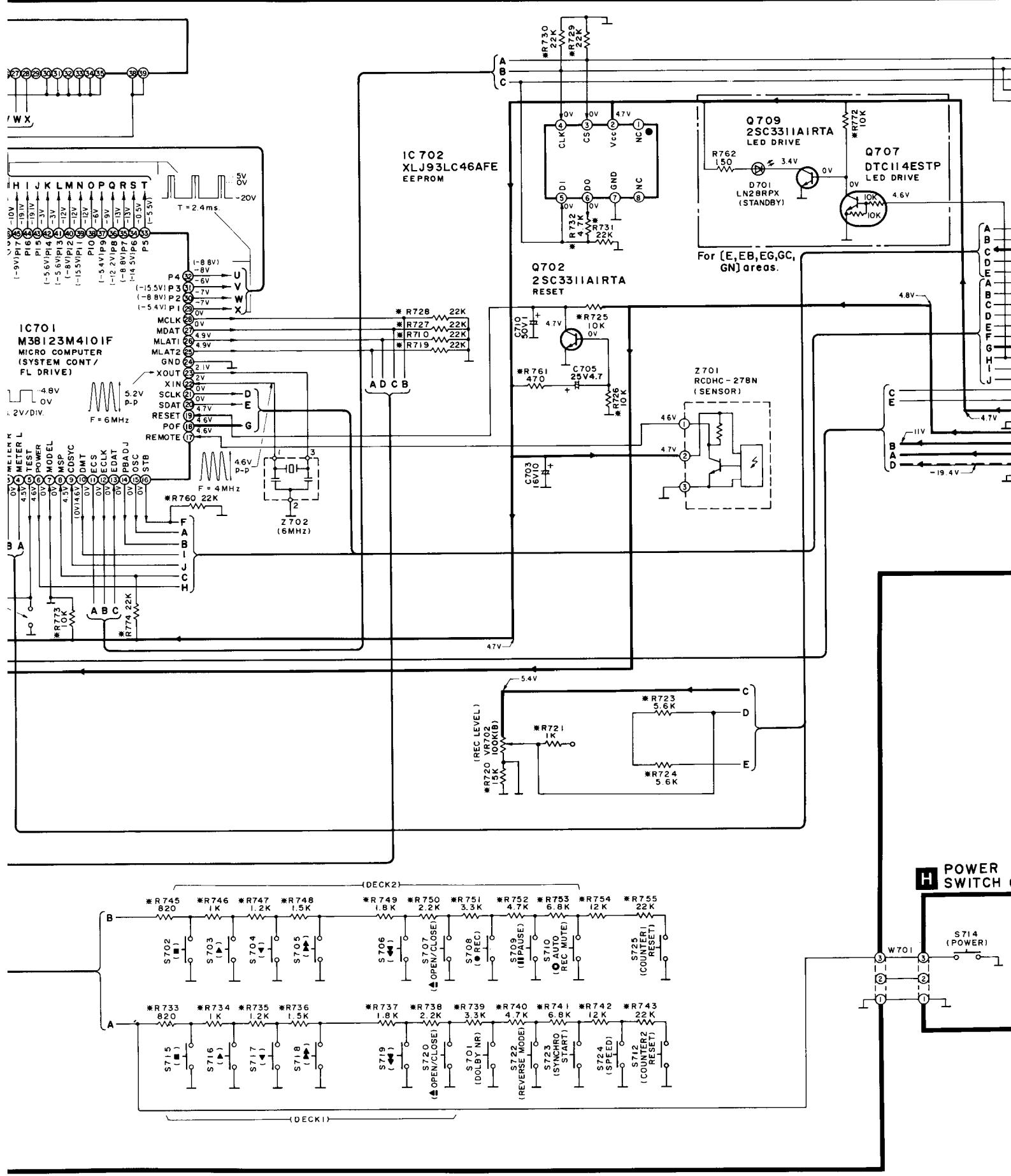
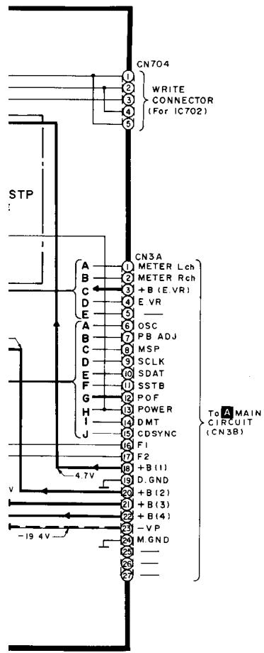
SCHEMATIC DIAGRAM (Parts list on pages 57~60.)
(This schematic diagram may be modified at any time with the development of new technology.)
Note 1:
S601 : Voltage selector in "240V" position. (For [GC] area only.) (110V 127V 220V 240V)
S701 : Dolby noise-reduction switch (DOLBY NR; ⑧, ⑨).
-
S702 : DECK 2 Stop switch (■).
-
S703 : DECK 2 Forward-side playback switch (▶).
-
S704 : DECK 2 Reverse-side playback switch (▲).
S705 : DECK 2 Fast-forward search switch (▶ TPS).
S706 : DECK 2 Rewind search switch (▲ TPS)
- S707 : DECK 2 Open/close switch (▲ OPEN/CLOSE).
S708 : DECK 2 Record switch (●REC).
S709 : DECK 2 Pause switch (PAUSE).
S710 : DECK 2 Automatic-record-muting switch ( AUTO REC MUTE).
S712 : DECK 2 Counter reset switch (COUNTER 2 RESET).
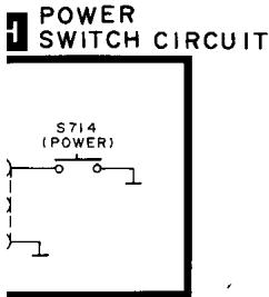
- S714 : Power "STANDBY /ON" switch (POWER, STANDBY /ON).
S715 : DECK 1 Stop switch (■)
S716 : DECK 1 Foward-side playback switch (▶).
- S717 : DECK 1 Reverse-side playback switch (▲).
S718 : DECK 1 Fast-forward search switch (▶ TPS).
S719 : DECK 1 Rewind search switch ( TPS).
- S720 : DECK 1 Open/close switch (▲ OPEN/CLOSE).
S721 : Auto tape calibration switch (ATC).
- S722 : Reverse-mode select switch (REVERSE MODE).
S723 : Synchro-start switch (SYNCHRO START).
S724 : Tape-to-tape recording-speed switch (SPEED; X1, X2).
S725 : DECK 1 Counter reset switch (COUNTER 1 RESET)
S801 : DECK 1 Cassette holder open detection switch in “off” position.
S802 : DECK 1 Cassette holder close detection switch in “off” position.
S803 : DECK 2 Cassette holder open detection switch in "off" position.
S804 : DECK 2 Cassette holder close detection switch in "off" position.
- S971 : DECK 1 Mode switch in "off" position.
S971A: DECK 2 Mode switch in "off" position.
S972 : DECK 1 Half switch in "off" position.
S972A:DECK2Half switch in"off"position.
S973 : DECK 1 ATS (CrO_2) switch in "off" position.
S973A: DECK 2 ATS (CrO_2) switch in "off" position.
S974A:DECK2Reverse rec.inhibit switch in"off"position.
S975A: DECK 2 Forward rec. inhibit switch in "off" position.
S976A:DECK2ATS(Metal) switch in "off" position.
- Resistance are in ohms () , 1/4 watt unless specified otherwise.
1K=1,000 (Ω), 1M=1,000k (Ω)
- Capacity are in micro-farads ( F) unless specified otherwise.
- All voltage values shown in circuitry are under no signal condition and playback mode with a volume control at minimum position otherwise specified.
( ).....Voltage values at record mode.
For measurement us EVM.
- Important safety notice
Components identified by mark have special characteristics important for safety. When replacing any of these components, use only manufacturer's specified parts.
- (一 + B) indicates + (bias).
- (= = = < -B > = = =) indicates -B (bias).
- ( ) indicates the flow of the playback signal.
( ) indicates the flow of the record signal. - The supply part number is described alone in the replacement parts list,
| Ref. No. | Production Part No. | Supply Part No. |
| IC152 | XLU2040F-T2 | XLU2040F-T1 |
| IC302 | BA4560FT1 | SVIBA4560FT1 |
※ marks indicate printed resistor.
Caution!
IC and LSI are sensitive to static electricity.
Secondary trouble can be prevented by taking care during repair.
- Cover the parts boxes made of plastics with aluminum foil.
Ground the soldering iron.
- Put a conductive mat on the work table.
- Do not touch the legs of IC or LSI with the fingers directly.
Marque : TECHNICS
Modèle : RS-TR337
Catégorie : Lecteur de cassette