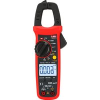
UT204R - équipements de mesure Uni-T - Notice d'utilisation et mode d'emploi gratuit
Retrouvez gratuitement la notice de l'appareil UT204R Uni-T au format PDF.


| Type de produit | Pince ampèremétrique numérique |
| Marque | Uni-T |
| Modèle | UT204R |
| Affichage | LCD numérique, 3 ¾ digits (6000 points) |
| Fonctions principales | Courant AC/DC 600 A, tension AC/DC 600 V, résistance 60 MΩ, capacité 100 mF, fréquence 10 MHz, test de continuité, diode, température avec thermocouple K |
| Mesure True RMS | Oui, pour courant et tension alternatifs |
| Ouverture de pince | 40 mm max. |
| Alimentation | Pile 9 V type 6F22 |
| Autonomie approximative | 200 heures (avec pile alcaline) |
| Dimensions | 230 × 80 × 40 mm |
| Poids | 300 g (avec pile) |
| Sécurité | Catégorie de surtension CAT III 600 V, double isolation |
| Entretien et nettoyage | Essuyer avec un chiffon humide, ne pas utiliser de solvants. Retirer la pile si inutilisé longtemps. |
| Réparabilité | Pièces détachées disponibles (fusibles, pointes de test, thermocouple). Réparation par centre agréé recommandée. |
| Accessoires fournis | Pointes de test, pince crocodile, thermocouple K, pile 9 V, manuel d'utilisation |
FOIRE AUX QUESTIONS - UT204R Uni-T
Questions des utilisateurs sur UT204R Uni-T
0 question sur cet appareil. Repondez a celles que vous connaissez ou posez la votre.
Poser une nouvelle question sur cet appareil
Téléchargez la notice de votre équipements de mesure au format PDF gratuitement ! Retrouvez votre notice UT204R - Uni-T et reprennez votre appareil électronique en main. Sur cette page sont publiés tous les documents nécessaires à l'utilisation de votre appareil UT204R de la marque Uni-T.
MODE D'EMPLOI UT204R Uni-T
UT203R/UT204R AC/DC Clamp Meters User Manual
Preface
Thank you for purchasing the new clamp meter. In order to use this product safely and correctly, please read this manual thoroughly, especially the Safety Instruction part.
After reading this manual, it is recommended to keep the manual at an easily accessible place, preferably close to the device, for future reference.
Limited warranty and liability
Uni-Trend guarantees that the product is free from any defect in material and workmanship within one year from the purchase date. This warranty does not apply to damages caused by accident, negligence, misuse, modification, contamination and improper handling. The dealer shall not be entitled to give any other warranty on behalf of Uni-Trend. If you need warranty service within the warranty period, please contact your seller directly.
Uni-Trend will not be responsible for any special, indirect, incidental or subsequent damage or loss caused by using this device. As some countries or regions do not allow limitations on implied warranties and incidental or subsequent damages, the above limitation of liability may not apply to you.
1. Overview
The UT203R/UT204R are portable true RMS AC/DC clamp meters with automatic range. They are designed according to EN61010-1 CAT II 600V/CAT III 300V safety standards, and come with full-function protection which ensures users a safe and reliable measurement experience. Aside from basic measurement functions, they also have high precision current scale and high voltage frequency measurement extension.
2. Features
• True RMS measurement
• Audio visual NCV electric field detection
- High voltage frequency range: 10Hz\~60kHz; low voltage frequency range: 60Hz\~10MHz
- UT203R AC/DC current range: 40A, 400A, frequency response: 45Hz\~400Hz
- UT204R AC/DC current range: 60A, 600A, frequency response: 45Hz\~400Hz, live/neutral wire detection
- ACA/DCA mode memory function for current measurement
- Large capacitance (UT203R: 40mF, UT204R: 60mF) and temperature Tmeasurement (U 204R)
- Large LCD and fast refresh rate (3 times/s), capacitance measurement response time:
≤1mF: less than 3s; ≤10mF: about 6s; ≤60mF: about 8s
• Full-function false detecting protection for up to 600V (3.6kVA) energy surge; overvoltage and overcurrent alarm
- The power consumption without backlight is about 1.8 mA. The circuit has an automatic power saving function. The consumption in sleep state is <11uA, which effectively extends the battery life to 400 hours.
Please read the safety and warning parts in this manual thoroughly.
Caution: Please read the safety instructions carefully before use.
3. Standard Accessories
Open the package and check the below items, if any is missing or damaged, please contact your supplier immediately:
User manual 1 pc
Test leads 1 pair
K-type temperature probe ---- 1 pc (Only UT204R) Cloth bag ---- 1 pc
4. Safety Instructions
WARNING
To ensure safe operation and service of the tester, follow these instructions. Failure to observe these warnings can result in severe injury or death.
The meter is designed according to EN61010-1, 61010-2-032/033 and electromagnetic radiation protection EN61326-1 safety standards, and conforms to double insulation, CAT II 600V, CAT III 300V and pollution grade II. In case the meter is not used properly as instructions the protection provided may be weakened or lost.
- Before each use verify tester operation by measuring a known voltage.
- Before use, please check if there is any item which is damaged or behaving abnormally. If any abnormal item (such as bare test lead damaged meter casing, broken LCD, etc.) is found, or if the meter is considered to be malfunctioning, please do not use the motor.
- Do not use the meter if the rear cover or the battery cover is not covered up, or it will pose a shock hazard!
- Keep fingers behind the finger guards and away from the metal probe contacts when making measurements.
- The function switch should be placed in the correct position before measurement. It is forbidden to change the position during measurement to avoid damage to the meter!
- Do not apply voltage over 600V between any meter terminal and earth ground to prevent electric shock or damage to the meter.
- Use caution when working with voltages above AC 30Vr.m.s, 42Vpeak or DC 60V. Such voltages pose a shock hazard.
-
Never input voltage or current which exceeds the specified limit. Maximum range should be selected if measured value is unknown. Before measuring resistance, diode and continuity, please disconnect all power and fully discharge all capacitors to avoid inaccuracy.
-
When the “☐” symbol appears on the LCD, please replace the batteries in time to ensure measurement accuracy. Batteries should be removed If the meter is long-term idle.
- Do not change the internal circuit of the meter to avoid damage to the meter and user!
- Do not expose the meter in high temperature/humidity, flammable, explosive or intense magnetic environments.
-
Clean the meter casing with a soft cloth and mild detergent. Do not use abrasives or solvents!
-
Symbols
| Symbol | Description |
| Caution, possibility of electric shock | |
| Alternating current | |
| Direct current | |
| Equipment protected throughout by DOUBLE INSULATION or REINFORCED INSULATION | |
| Earth (ground) TERMINAL | |
| Warning or Caution | |
| Conforms to UL STD 61010-1, 61010-2-032, 61010-2-033,Certified to CSA STD C22.2 No. 61010-1, 61010-2-032,61010-2-033. | |
| CAT II | It is applicable to test and measuring circuits connected directly to utilization points socket outlets and similar points of the low voltage MAINS installation |
| CAT III | It is applicable to test and measuring circuits connected to the distribution part of the building's low voltage MAINS installation |
6. General Specifications
• Max LCD display counts: 4099 (U 203R), 6099 (U 204R)T T
• Polarity display: Auto
• Overload display: "OL" or "-OL"
- Low battery indication: "☐" means low battery
- Low battery shutdown prompt: The "Lo.bt" interface appears on LCD and lasts for about 10s, the buzzer beeps 3 times, and the meter automatically shuts down.
- Test position error: If the source under test is not placed at the center of the clamp jaws when measuring current, ± 1.0% additional error in reading may be produced.
- Drop protection: 1m
• The maximum size of jaw opening: 28mm in diameter
- Battery: AAA 1.5V battery × 2
- Auto power off (adjustable): The meter will auto power off if there is no operation for 15 min.
• Dimensions: 215mm × 63.5mm × 36mm
• Weight: About 235g (including batteries)
• Altitude: 2000m
- Operating temperature and humidity: 0°C\~30°C (≤80%RH), 30°C\~40°C (≤75%RH), 40°C\~50°C (≤45%RH)
- Storage temperature and humidity: -20°C\~+60°C (≤80%RH)
- Electromagnetic compatibility: RF=1V/m, overall accuracy=specified accuracy+5% of range; RF>1V/m, no specified calculation
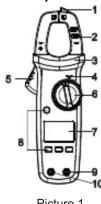
7. External Structure (Picture 1)
1) NCV sensing end
2) Clamp jaws
3) Hand guard
4) LED indicator
5) Jaw opening trigger
6) Function scale level
6) Function sea
1) LOD display
8) Function buttons
9) Signal input jack (red and positive +)
10)COM input jack (black and negative -)
8. Button Description
SELECT Button
In composite scale, press this button to switch between the corresponding functions or ranges;
HOLD/BACKLIGHT Button
Short press this button to enter/exit the data hold mode, and long press (about 2s) this button to turn on/off the backlight.
MAX/MIN Button
(valid for ACV/DCV, ACA/DCA, "C"/F, resistance and capacitance scales) Short press this button to enter the maximum/minimum measurement mode and long press this button to exit.
REL Button
(valid for ACV/DCV, DCA, "C/"F and capacitance scales).
Press this button to store the current reading as a reference for future readings. When the LCD display value is reset to zero, the stored reading will be subtracted from the future readings. Press this button again to exit the relative value mode.
9. Operating Instructions
9.1 AC/DC Current Measurement (Picture 2)
- Select the corresponding current range.
- Press the trigger to open the clamp jaws, and fully enclose one conductor.
- Only one conductor can be measured at a time, or the measurement reading will be wrong.
Caution:
- Do not insert the testing leads during current measurement to avoid electric shock.
• The current measurement must be taken with safeguard protection.
- Press the REL button to return to zero before the DC current measurement, and meanwhile the center hole of jaw should be perpendicular to the current direction to ensure accuracy.
- The open circuit zeroing reading may be relatively large after (high) DC current measurement. Please perform the AC current detection again to counteract the remanence signal by alternating electric field.

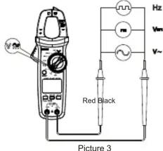
9.2 AC/DC Voltage and Voltage Frequency (% duty cycle) Measurement (Picture 3)
- Select the corresponding function scale.
- Insert the red test lead into the "positive" jack, and the black into the "COM" jack.
- Connect test leads with both ends of the measured objects.
Caution:
- Do not input voltage above 600V to prevent electric shock or damage. The input impedance of each range scale is 10MΩ, this load effect in high resistance measurement may cause error. If the input impedance is lower than 10kΩ, the error can be ignored (≤0.1%).
- Be cautious to avoid electric shock when measuring high voltage.
- Please check the functions by applying a known voltage before use.
9.3 Continuity Test/Resistance/Diode/Capacitance
Measurement (Picture 4)
- Select the corresponding function scale.
- Insert the red test lead into the "V+Ω+Hz" jack, and the black into the "COM" jack.
- Connect test leads with both ends of the measured object.
Caution:
- Do not input voltage above DC 60V or AC 30V to avoid personal injury.
- Please disconnect all the other parts of the circuit to avoid inaccuracy.
- Before the resistance online measurement, please do disconnect all the power and fully discharge all capacitors to avoid injury or device damage.
- If the resistance is over 0.5Ω when the test leads are short-circuited, please check the test leads for looseness or other abnormalities
- If the measured resistor is open or the resistance exceeds the maximum range, the LCD will display "OL".
- Measured value = displayed value – probe short circuit value
- It is recommended to use "REL" measurement mode for capacitance less than 100nF.

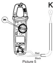
9.4 Temperature Measurement (UT202R only, Picture 5)
- Select the temperature measurement function scale.
- Insert K-type thermocouple to the meter, fix the temperature probe on the measured object, and read after the value is stable.
9.5 NCV AC Electric Field Serving (Picture 6a)
The electric field are an overall city divided into junctions.
(“EIFH” and EPLo). The motor defaults to EIFH. Users can select different sensitivity levels according to the intensity of the measured electric field. Select “EIFH” of NCV when electric field is around 20V AC SIN/65Hz. Bring the NCV arrangement down to a charged electric field (packet, isolated wire, etc.). The LCD will display the segment “with beeps and notLED flashing. As the intensity of the measured electric field increases, the more segments (—) display, the higher frequency of buccal beeps and LED flashes. Select EFLo when the electric field is around 110 VAC SIN/65Hz.
Caution
Use the NC V sensing and to approach measured electric field, otherwise as the measurement sensitivity will be affected. When the measured electric field voltage is over 100VAC, observe whether the conductor is inhaled to avoid personal injury

Picture 6a
9.6 Others
- Also power off: The motor will automatically power off to save power if there is no operation for 15 hrs. You can walk up by pressing any button or set back. After Amortization is able to OFF.
- Press and hold the SELECT button in off state-end then turn on the meter again to edit the autopower diffunction, feedat themler after what it down to resume the function.
- Buzzer: When any button is pressed or the function switch is turned, if it is valid, the buzzer estimate one beep (about 0.256). The buzzer will also keep intermittently to indicate the over range during the voltage or current measurement.
- Low battery detection: The battery voltage will be automatedly detected as long as the meter is on. If it is lower than 2.6V, the LCD will display the "▲3" symbol.
- Low battery shutdown function: When the battery voltage is lower than 2.5V, the LCD displays the “☐” symbol, the “Lo tf” interface appears and lasts for about 10s, the buzzer w/les a consecutive beeps 3 times, and then the meter automatically shuts down (no interference is displayed).
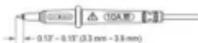
10. Probe usage
TESTING IN CAT III MEASUREMENT LOCATIONS Ensure the test lead shield pleased firmly in place. Failure to use the CAT III shield illnesses and flash risk.
▲Caution
• Accuracy guarantees range: 5%-100% of range
- When the measured current reaches the warning value, there will be a proof that (1/T2079, 4103) is T2049, 5103).
- 15th DC current DGA mode LCE may display groups
In open circuit state, users can prive "FEL" function to dear display
to zero before each two agreement
10.2 Voltage Measurement
DC Voltage
| Range | Resolution | Accuracy | |
| UT2.03R | UT204R | ||
| 400.0mV | 600.0mV | 0.1mV | ± 0.7 +3 |
| 4.000V | 6.000V | 0.001V | ± 0.5 +2 |
| 40.0kV | 60.0kV | 0.01V | |
| 400.0V | 600.0V | 0.1V | |
| 600V | 1V | ||
AC Voltage/Voltage Frequency
| Range | Resolution | Accuracy | |
| UT203R | UT 204R | ||
| 4.00V | 6.00V | 0.01V | ± 11.0 - 15 |
| 41.00V | 60.00V | 0.01V | ± 12.8 - 15 |
| 430.0V | 600.0V | 0.1V | |
| 6.00V | 1V | ||
| Voltage Frequency10 Ω-600 Ω | 0.01Hz~0.07Hz | ± 10 (5Hz) | |
▲Cution
- UT203R: short press "SELECT" in AC voltage/Hz scale to enter the Hz
FUNCTION:
Otras-4PC long press -SICL2C 1-10 entwelt the RA function, thermal range over 5V.
• The input impedance is about (OMC)
- Current voltage frequency response: 45Hz \~400Hz; displays true RMS
value ■ Accuracy measures group: 5%+100%
- AC crest factor of non-sinu apoidal wave can reach 310 at 4000 counts
while can only reach 1.8 at € 000 counts, the additional error should be adjusted for the previous year's estimates and details.
added for the corresponding green factory operations. A hold 3% when the green factory is 1 >2
B. Add 5% when the peak factor is 2 \~2.5
C. Add 7% when the peak factor is 2.5\~3
10.3 Commodity Credit Measure Note
| Function | Range | Resolution | Accuracy |
| 40.00/600.00 | 0.10 | ± 100 . Consecutive beeps2/30. No beepThe median uncertain | |
| 40.00/60.00/6 | 0.001V | The open circuit voltage is about 4VFor the silicon PN junction diode, the voltage value is generally about 0.5~0.8V |
10.4 Resistance Measurement
| Range | Resolution | Accuracy | |
| 0.120R | 0.120R | ||
| 400.0Ω | 600.0Ω | 0.1Ω | ±0.0-0.2 |
| 4.030Ω | 6.000Ω | 0.001KΩ | |
| 40.00Ω | 60.000Ω | 0.01KΩ | ±0.8-0.2 |
| 400.1Ω | 600.1Ω | 0.1KΩ | |
| 4.000Ω | 6.000Ω | 0.001MΩ | ±(2.5V+5) |
| 40.00Ω | 60.000Ω | 0.01MΩ | |
Dutyrate is only applicable to c10% for square wave measurement
with a range of 1'4p-p
IFrequency: Hard, daily cycle write 10.0%-48.0%, if two were facilities, did only sell to 30.0%-79.0%.
- Valgazetop - No 2, Lasj. Optar and de Sotro-3018
10.8 Temperature Measurement (UT204R only)
| Range | Resolution | Accuracy |
| -40°C~40°C | 1°C | ± 4°C |
| 40°C~500°C | ± (0.55 × 5) | |
| 500°C~1000°C | ± (2.05 × 5) | |
| -40°F~104°F | 1°F | ± 6°F |
| 104°F~932°F | ± (2.05 × 5) | |
| 932°F~1832°F | ± (2.05 × 5) |
Caution
The name displays "CL" after startup, 8 monthly infrastructureType
thermocouple (Nickel-Chelvare + Nickel-Silicon temperature
sermorytal bevperolara ramaarsetzemi Innoe 1000/CF10032/F.
10.9 NCV
| Range | Electric field sensitivity sensitivity level | Accuracy |
| MCV | EFLa | The electric field sensitivity sensitivity is divided into two levels (TFLA, TFLb). The reader defaults to TFLc at AC voltage above 20V/Hz cable ranges (TFLa) model is recommended when the power frequency voltage is 115V. |
| EPH | To TFLc can be set in 22V condition, AC voltage above 16V/Hz can be measured by getting clients seen and identify whether the main socket is charged to judge the instrument side of socket according either in density of sensing. | |
| #None Test results may be affected by different socket designs or wire I radiation thickness. |
11. Maintenance
1 By virtue: Reflexopressivity macrocryst of make, common but
lauch to meidlofodric; nheck
11.1 General Maintenance
- Clean the meter casing with a soft cloth and mild detergent. Do
risk use abrasives or advened
- Chg. Roll costs (for limited to total needs) if they apply to /aven, any above royalty.
• File or system
- Transportation and thermal heat de Implementation by organized professionals or designated departments.
11.2 Battery Replacement (Picture 7)
When the 'C' symbol appears on the LCD, please replace the
Batteries, infineolensure measurement accuracy. Batteries
- Standard SAA 1-IV Computer
Deutschia
- Turnoff the reader and return the tool leads from the input terminals - Unknown the screen of the ontology correspondence, return the ontology cover, and filter out the unambiguities as straws.
- UT203R/UT204R AC/DC CLAMP METERS USER MANUAL
- PREFACE
- LIMITED WARRANTY AND LIABILITY
- OVERVIEW
- FEATURES
- STANDARD ACCESSORIES
- SAFETY INSTRUCTIONS
- WARNING
- GENERAL SPECIFICATIONS
- EXTERNAL STRUCTURE (PICTURE 1)
- BUTTON DESCRIPTION
- SELECT BUTTON
- HOLD/BACKLIGHT BUTTON
- MAX/MIN BUTTON
- REL BUTTON
- OPERATING INSTRUCTIONS
- 9.1 AC/DC CURRENT MEASUREMENT (PICTURE 2)
- CAUTION
- 9.2 AC/DC VOLTAGE AND VOLTAGE FREQUENCY (% DUTY CYCLE) MEASUREMENT (PICTURE 3)
- 9.3 CONTINUITY TEST/RESISTANCE/DIODE/CAPACITANCE
- MEASUREMENT (PICTURE 4)
- 9.4 TEMPERATURE MEASUREMENT (UT202R ONLY, PICTURE 5)
- 9.5 NCV AC ELECTRIC FIELD SERVING (PICTURE 6A)
- 9.6 OTHERS
- PROBE USAGE
- ▲CAUTION
- ▲CUTION
- MAINTENANCE
- 11.1 GENERAL MAINTENANCE
- 11.2 BATTERY REPLACEMENT (PICTURE 7)
- DEUTSCHIA
Marque : Uni-T
Modèle : UT204R
Catégorie : équipements de mesure