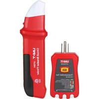
UT25B - Coupe-circuits Uni-T - Notice d'utilisation et mode d'emploi gratuit
Retrouvez gratuitement la notice de l'appareil UT25B Uni-T au format PDF.


| Type de produit | Coupe-circuits (disjoncteur) |
| Marque | Uni-T |
| Modèle | UT25B |
| Dimensions (L x H x P) | 18 x 80 x 70 mm |
| Poids | 100 g |
| Tension nominale | 230 V AC |
| Courant nominal | 16 A |
| Pouvoir de coupure | 6 kA |
| Norme | IEC 60898 |
| Fonctions principales | Protection contre les surcharges et courts-circuits, commutation manuelle marche/arrêt |
| Entretien et nettoyage | Nettoyer avec un chiffon sec, vérifier périodiquement le fonctionnement |
| Sécurité | Débrancher l'alimentation avant toute intervention, utiliser des outils isolés |
| Pièces détachées et réparabilité | Non réparable, remplacer l'unité en cas de défaut |
| Informations générales | Disjoncteur unipolaire pour installation domestique, montage sur rail DIN |
FOIRE AUX QUESTIONS - UT25B Uni-T
Questions des utilisateurs sur UT25B Uni-T
0 question sur cet appareil. Repondez a celles que vous connaissez ou posez la votre.
Poser une nouvelle question sur cet appareil
Téléchargez la notice de votre Coupe-circuits au format PDF gratuitement ! Retrouvez votre notice UT25B - Uni-T et reprennez votre appareil électronique en main. Sur cette page sont publiés tous les documents nécessaires à l'utilisation de votre appareil UT25B de la marque Uni-T.
MODE D'EMPLOI UT25B Uni-T
UT25A, UT25B, UT25A/B Operations Manual
UT25A, UT25B as circuit breaker finder/receiver UT25A/B as socket tester/transmitter
Overall Appearances of Circuit Breaker Finder & GFCI Socket Tester:

Product Description
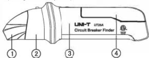
Receiver
- NCV indicator light (only for UT25B)
- LED indicator light with line-tracking
- ON/OFF switch that can also adjust sensitivity
- 9VDC, battery type 1604/6F22
Attention: The battery information on the battery compartment and the method of opening the battery compartment
Transmitter
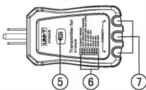
- GFCI test button
- Indicator light description
- LED status indicator
| When this symbol appears, the operator should refer to the Operations Manual to avoid personal injury or damaging the meter. | |
| WARNING | When this symbol appears, it hints that there could be potential danger which might lead to severe injury or death or if the danger is not avoided. |
| CAUTION | When this symbol appears, it hints that there is potential danger which might damage the product if the danger is not avoided. |
| Conforms to UL STD. 61010-1, Certified to CSA STD C22.2 NO. 61010-1 |
Product Specification for UT25A and UT25B
| NCV working voltage | 80V(only for UT25B) |
| Operating voltage | 90-120V |
| Operating frequency | 50-60Hz |
| Power | 9VDC, battery type 1604/6F22 |
| Operating temperature | 41°F - 104°F (5°C - 40°C) |
| Storage temperature | 4°F - 140°F (-20°C - 60°C) |
| Operating humidity | at most 80% at temperature of 87°F (31°C) to 50% at temperature of 104°F (40°C) Storage humidity |
| Operating altitude | 7000 feet (2000m) at most product weight |
| 133g (UT25A, UT25B) | |
| 80g (UT25A/B) | |
| Product size | L:192xW:54xH:28mm (UT25A, UT25B) |
| L:103xW:56xH:30mm (UT25A/B) | |
| Product certification | ETL |
| ETL list | ETL mark does not indicate the accuracy of estimated readings |
Operations
Warning: Make sure that the circuit
is functioning properly before using.
Warning: Make sure the user
understands about the equipment.
Find the location of circuit breaker or circuit protector on the power frequency circuit loop, the transmitter will then send out a signal which will be received by the receiver. The receiver will detect this signal which is making beeping sounds, the exact position of circuit breaker or circuit protector can be found by adjusting the positivity
by adjusting the sensitivity.
- Plug the receiver into a live socket; two green LEDs will shine.
- Unscrew the sensitivity adjusting knob on the receiver from the close position to the highest position, the red LED will be turned on. If the red LED did not turn on, please change the battery. It is also necessary to change the battery if the NCV indicator light and line-tracking light are both blinking (only for UT25B).
- During the testing process, when the receiver is close to the transmitter, the receiver will make beeping sounds and the LED will blink. UT25B (only) will firstly determine if there is electricity or not. If there is an AC voltage higher than 80V, the NCV indicator light will blink and make beeping sounds. When it detects signal sent out by the transmitter, it will automatically test the line-tracking function.
- On the circuit breaker panel, adjust the sensitivity to the highest position, hold the receiver and detect from top to bottom, as shown in the figure above.
- Along with the surface of circuit breaker, move the receiver until it detects the portion of interest.
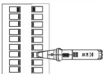
(Detection Image of Receiver)
(No text)
con LEDs will china
then EEDS Will Shine.
If the receiver from the close position turned on. If the red LED did not turn on, ssary to change the battery if the NCV 6th blinking (only for UT25B).
Receiver is close to the transmitter, the LED will blink. UT25B (only) will not. If there is an AC voltage higher than and make beeping sounds. When it will automatically test the
ensitivity to the highest position, hold
as shown in the figure above.
move the receiver until it detects the
- When moving the receiver, the sensitivity can be reduced to find the exact circuit breaker of interest.
Product Specification for UT25A/B
| Working voltage | 110-125V |
| Operating frequency | 50-60Hz |
| Fuse | 1A, 250V, ∅4x11mm |
WARNING: If the equipment is used in a manner not specified by the
manufacturer, the protection provided by the equipment may be impaired.
Indicator Light Description:
| CORRECT WIRING.... | ● | ○ | ● |
| GFCI TESTING IN PROGRSS.... | ● | ● | ● |
| HOT ON NEU WITH HOT OPEN.... | ○ | ● | ○ |
| HOT & GND REV.... | ○ | ● | ● |
| HOT & NEU REV.... | ● | ● | ○ |
| OPEN HOT.... | ○ | ○ | ○ |
| OPEN NEU.... | ○ | ○ | ● |
| OPEN GND.... | ● | ○ | ○ |
| ○ OFF ● ON |
- Plug the transmitter into the socket.
- The operator can determine the status of circuit connection according to the 3 LEDs. The picture above shows all of the circumstances that can appear on the detected circuit. The picture is observed from the side of GFCI buttons. If it is observed from the other side, the order of LED indicator lights will be mirrored.
- This equipment cannot detect the ground connection if there are 2 hot wires, a combination circuit, or the ground and neutral wires are reversed
GFCI Test on Socket:
- Before using this equipment, press GFCI button to check if it can return to the original position. If not, please do not plug the equipment into electrical circuit, and ask for a professional electrical engineer for help. If the button works, please press the button on the socket.
- Plug the transmitter into socket and check if the circuit is connected correctly.
- Press GFCI button for at least 8 seconds, the indicator light will be turned off when the GFCI button is released.
- If the circuit did not reset the GFCI button, it could be that the GFCI button is correct, but the wire connection is not. Or it could be that the wire connection is correct, but the GFCI button is not.
Changing Battery:
- When the battery voltage is lower than the working voltage, the indicator lights on the receiver will not be turned on, please change the battery. If the NCV indicator and the line-tracking lights are both blinking (only for UT25B), please change the battery as well.
- Slide open the battery cover according to the arrow direction on the battery cover and take out the used battery.
- Install a new 9V battery while paying close attention to the battery polarity
- Close the battery cover.
- Put the used battery in a special battery disposal area.
UNI-T.
UNI-TREND TECHNOLOGY (CHINA) CO., LTD.
No6, Gong Ye Bei 1st Road,
Songshan Lake National High-Tech Industrial
Development Zone, Dongguan City,
Guangdong Province, China
Tel: (86-769) 8572 3888
http://www.uni-trend.com
Marque : Uni-T
Modèle : UT25B
Catégorie : Coupe-circuits