LX-2200 - Projecteur de film Elmo - Notice d'utilisation et mode d'emploi gratuit
Retrouvez gratuitement la notice de l'appareil LX-2200 Elmo au format PDF.


| Type de produit | Visualiseur (document camera) |
| Marque | Elmo |
| Modèle | LX-2200 |
| Résolution maximale | 1920 x 1080 pixels (Full HD) |
| Grossissement optique | 12x |
| Grossissement numérique | Jusqu'à 4x |
| Écran intégré | Non (sortie HDMI/VGA) |
| Connectivité | HDMI, VGA, USB, entrée audio |
| Source lumineuse | LED intégrée |
| Dimensions (L x P x H) | 320 x 240 x 120 mm |
| Poids | 1,5 kg |
| Alimentation | Adaptateur secteur 12V 2A |
| Consommation électrique | 15 W |
| Température de fonctionnement | 5°C à 35°C |
| Fonctions principales | Capture de documents, zoom, mise au point automatique, rotation d'image, annotation |
| Formats d'image supportés | JPEG, PNG, BMP |
| Entretien et nettoyage | Nettoyer l'objectif avec un chiffon doux et sec. Éviter les solvants. |
| Sécurité | Ne pas exposer à l'humidité. Débrancher avant nettoyage. |
| Pièces détachées et réparabilité | Disponibles auprès du service après-vente Elmo. |
| Garantie | 2 ans |
| Accessoires inclus | Adaptateur secteur, câble HDMI, câble USB, guide de démarrage rapide |
| Utilisation prévue | Présentations en classe, réunions, vidéoconférences |
FOIRE AUX QUESTIONS - LX-2200 Elmo
Questions des utilisateurs sur LX-2200 Elmo
0 question sur cet appareil. Repondez a celles que vous connaissez ou posez la votre.
Poser une nouvelle question sur cet appareil
Téléchargez la notice de votre Projecteur de film au format PDF gratuitement ! Retrouvez votre notice LX-2200 - Elmo et reprennez votre appareil électronique en main. Sur cette page sont publiés tous les documents nécessaires à l'utilisation de votre appareil LX-2200 de la marque Elmo.
MODE D'EMPLOI LX-2200 Elmo
ELMO
16mm XENON-ARC LAMP SOUND PROJECTORS
LX-1100/LX-2200
INSTRUCTION MANUAL

CONTENTS
Page
I. INTRODUCTION 1
II. COMPONENTS 1
III. SPECIFICATIONS 2
IV. NOMENCLATURE 3
V. FUNCTION OF MAJOR COMPONENT PARTS 14
- Projection Control Switches 14
- Sound System Controls 15
- Other Controls 17
- Electric Bulbs 19
- Magnetic Playback System 19
- Film Transport Mechanism 19
- Others 20
VI. OPERATION PROCEDURE 21
- Lighting Xenon-Arc Lamp 21
- Film Threading 22
- Preparation before Projection 22
- Starting Projection 23
- Cautions during Projection 23
- After Projection 23
- Other Operation Hints 24
VII. MAINTENANCE HINTS 25
- Cleaning Projector 25
- Lubrication 25
- Replacing Major Component Parts 26
VIII. ELMO SCOPE LENS HOLDER 29
I. INTRODUCTION
Elmo 16mm Xenon-arc Lamp Sound Projectors, Models LX-1100/LX-2200 are stationary-type high-performance sound projectors equipped with 1000W (LX-1100) or 2000W (LX-2200) Xenon-arc lamp as light source and powerful 50W monaural (LX-1100) or 50W + 50W stereo (LX-2200) amplifier for both optical and magnetic playback, and are best suited for theater/auditorium use.
LX-1100/LX-2200 offer such superb features as outstanding screen brightness throughout its lamp's long service life and excellent sound performance in terms of frequency response, distortion, S/N ratio and so forth.
The operation is as simple as the operation with the conventional projectors and the Xenon-arc lamp ON/OFF can be done by just simple switching. Only one different point in operation is that the Xenon-arc lamp must be turned on before starting film run. Thanks to the safety shutter interlocked with film transportation and the specially-designed reflector incorporated into the lamp system, the film will be never damaged by heat.
To operate the projector in most effective way, please read through this instruction manual.
The following precaution must be faithfully exercised.
-
Avoid exerting shock against the projection lamp. The bulb of the Xenon-arc lamp is highly pressured. Particularly, when it is on, the interior pressure is further raised, and, therefore, no shock or impact should be given to the lamp.
-
Do not allow excessive electric current other than the specified one to the lamp. The lamp current is always kept constant so that no current fluctuation occurs while the operation is under way. The lamp circuit is pre-adjusted to the normal current setup at factory. If the current adjustment is necessitated by all means for good reason, adjust the current level by turning the rod in the lamp current adjusting hole. Don't raise the level of the lamp current beyond the red mark on the lamp ammeter.
-
When the Xenon-arc lamp is turned on, a high voltage of some 30,000V is applied. The lamp ignition circuit is safety-proofed; it is so arranged that no current is admitted if the lamphouse cover is removed. Don't remove the safety switch nor tamper the safety circuit. Any trouble or accident attributed to tampering of this circuit by unauthorized person will exempt us from any obligation or responsibility.
-
Don't insert metal piece or the like into the openings in the projector nor peep into the projector through the openings.
II. COMPONENTS
| Projector | : Projector properPedestalFeed reel arm |
| Attachment | : Power cord .... 1 pce.Elmo scope lens holder .... 1 pce.Reel holding knob .... 2 pcs. |
| Option | : Sound output cord2-strand sealed cord (5 m) with plug |
III. SPECIFICATIONS
| Powersupply | : Single phase AC 100-260V, 50 or 60 Hz. LX-1100Single phase AC 200-260V, 50 or 60 Hz. LX-2200 |
| Power consumption | : 3.4KVA . . . . LX-11004.6KVA . . . . LX-2200 |
| Film | : 16mm optical and magnetic sound films and 16mm optical sound film recorded with laser recording system, plus 16mm optical stereo/2-track sound films (LX-2200 only) |
| Projection speed | : 24 fps |
| Reverse projection | : Possible |
| Remote projection | : Possible (with optional remote control) |
| Changeover projection | : Possible (with optional connection cable) |
| Rewinding | : High-speed rewinding without changing over reels |
| Film break interlock switch | : Provided. In case film breaks during projection by accident, projector stops automatically. |
| Hour meter | : Built-in |
| Loop restorer | : Automatic |
| Reel capacity | : 1800 m (6000 ft) |
| Tilting | : -15° to +5° |
| Projector body | : Substantially casting aluminum alloy and steel sheet |
| Projection lamp | : 1000W Ozone-free Xenon-arc lamp . . . LX-11002000W Ozone-free Xenon-arc lamp . . . LX-2200 |
| Lamp current | : Max. 50A . . . . . . . . . . . . . . . . . . . . . . . . . . . . . . . . . . . . . . . . . . . . . . . . . . . . . . . . . . . . . . . . . . . . . . . . . . . . . . . . . . . . . . . . . . . . . . . . . . . . |
| Max. 80A . . . . . . . . . . . . . . . . . . . . . . . . . . . . . . . . . . . . . . . . . . . . . . . . . . . . . . . . . . . . . . . . . . . . . . . . . . . . . . . . . . . . . . . . . . . . . . . . . | |
| Light condensing system | : Multi-reflective with Oval mirror and Cold mirror installed in the lamphouse |
| Projection lens | : F/1.2 f-50mm Elmo projection lens as standard(Available a variety of projection lenses as option) |
| Film transport mechanism | : 3 sprockets; Intermittent film feeding apparatus provided with shutter and installed in a casing having therein Quadruple cam/Cylinder cam/Film transmitting claw/Gears; Film sending reel-arm; and Film winding device.Grease lubrication system. Automatic loop setter provided. Capable for reverse film-feeding. |
| Xenon-arc lamp actuator | : Generator for high voltage with high frequency ampere controller and monitor ammeter, which are built in the projector body. |
| Exciter lamp | : 4V-0.75A DC |
| Amplifier | : Pre/Main amplifier 1 pce. . . . . . . . . . . . . . . . . . . . . . . . . . . . . . . . . . . . . . . . . . . . . . . . . . . . . . . . . . . . . . . . . . . . . . . . . . . . . . . . . . . . . . . . . . . . . . . . . . . . . Pre/Main amplifier 2 pcs. . . . . . . . . . . . . . . . . . . . . . . . . . . . . . . . . . . . . . . . . . . . . . . . . . . . . . . . . . . . . . . . . . . . . . . . . . . . . . . . . . . . . . . . . . . . . . . . . . . |
(Specifications and design are subject to change without notice.)
IV. NOMENCLATURE

Fig. 1 (LX-2200 illustrated)

Fig. 2 (LX-2200 illustrated)
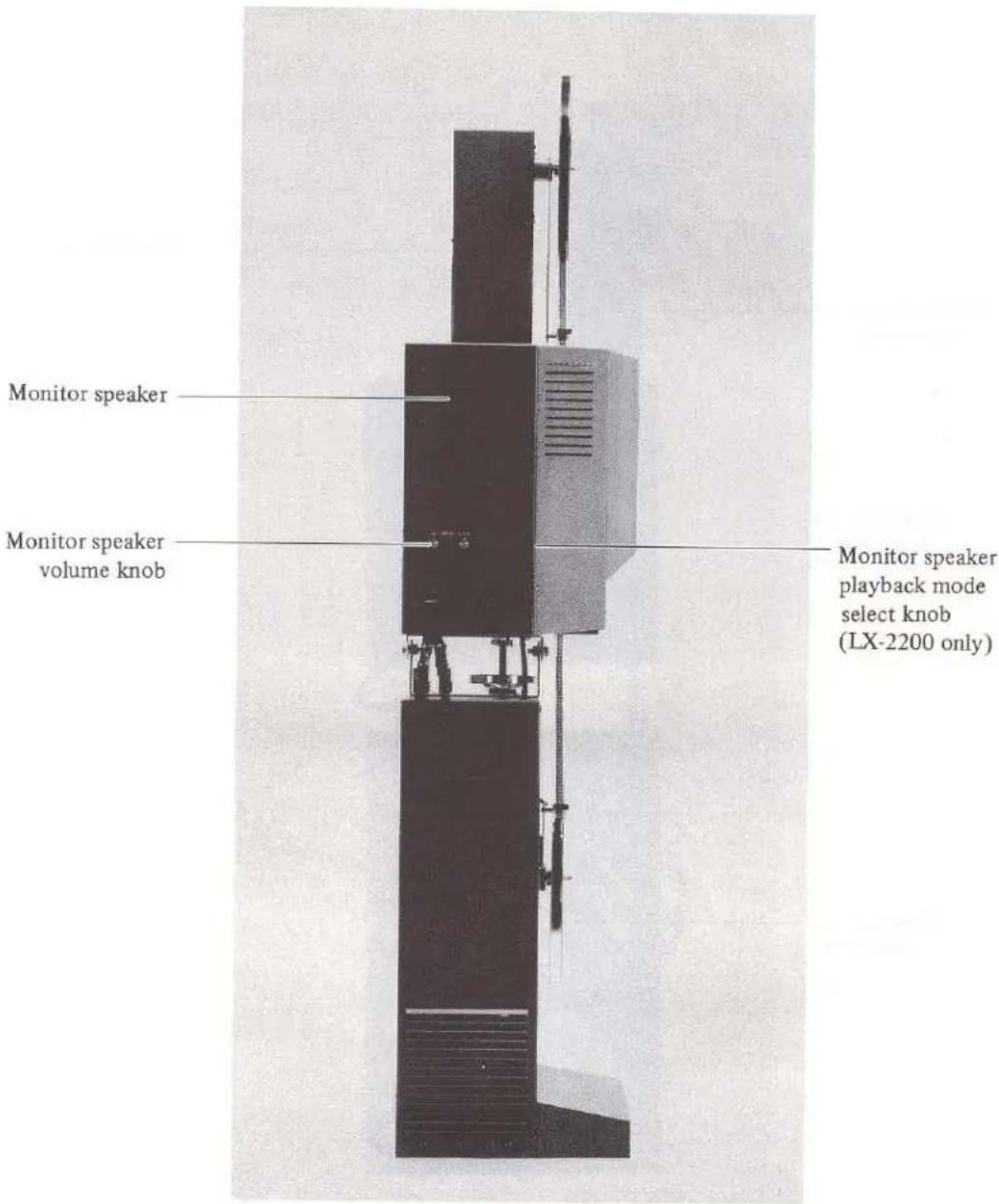
Fig. 3 (LX-2200 illustrated)
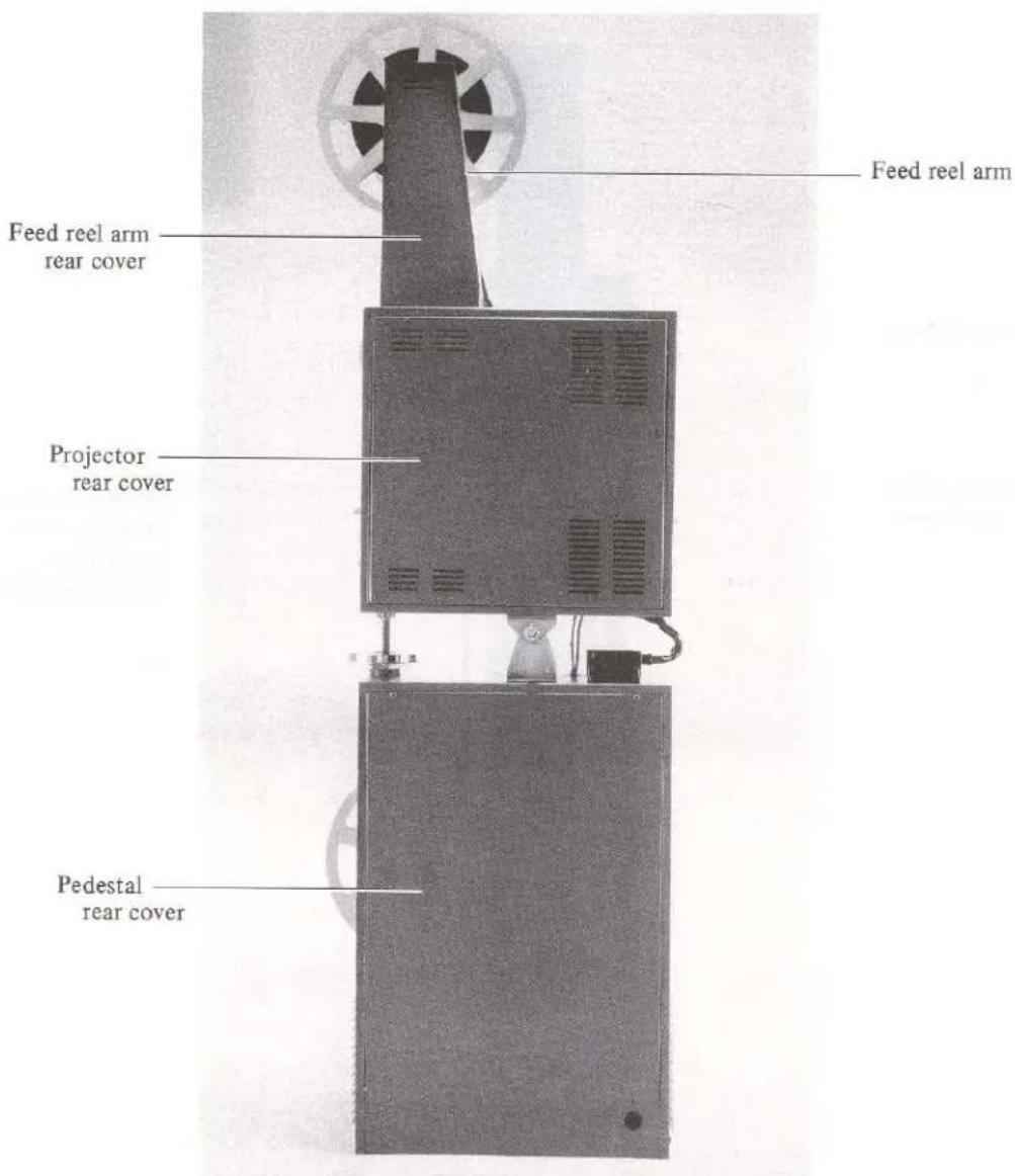
Fig. 4
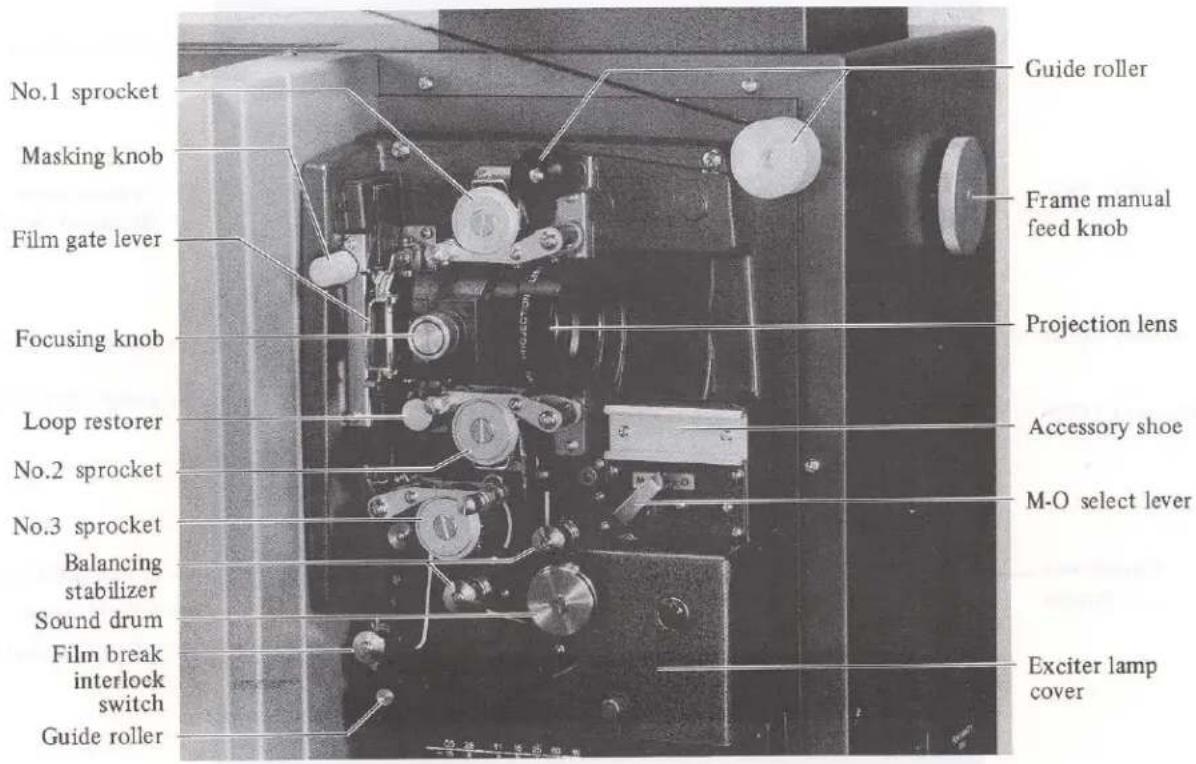
Fig. 5

Fig. 6-1 (LX-1100)
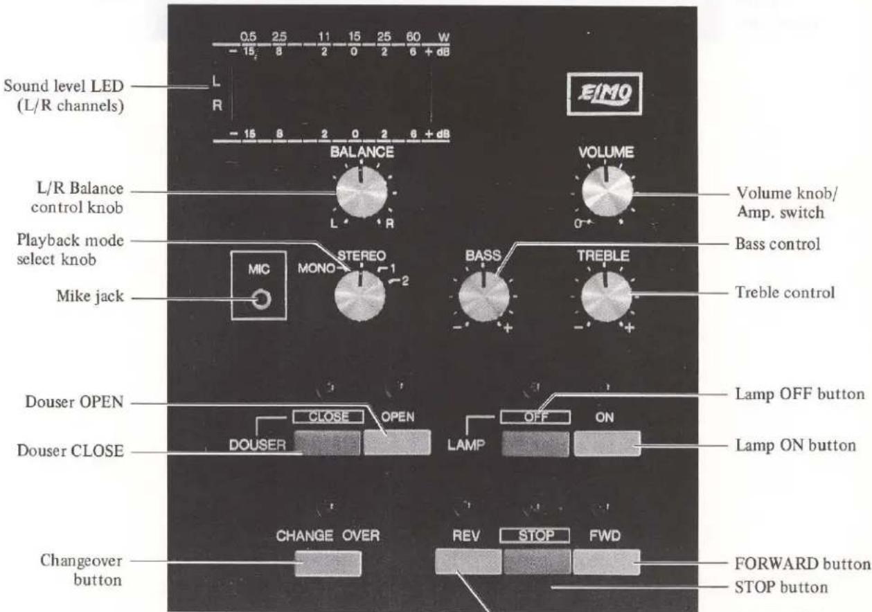
Fig. 6-2 (LX-2200)
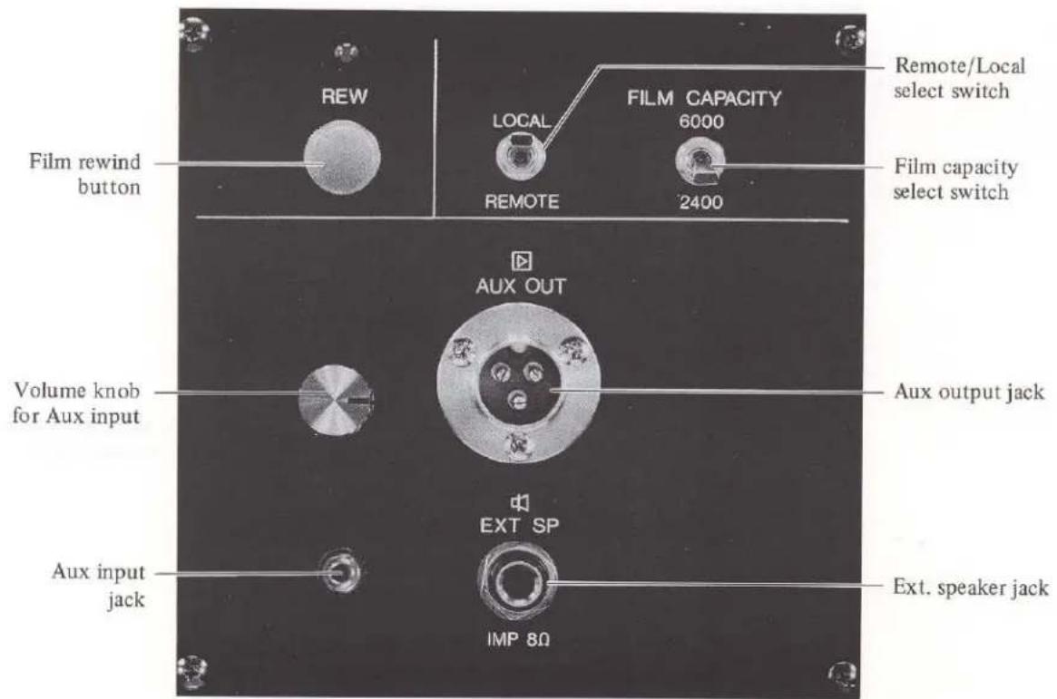
Fig. 7-1 (LX-1100)

Fig. 7-2 (LX-2200)
Monitor speaker volume knob
Monitor speaker
playback mode
select knob
Fig. 8-2 (LX-2200)
![graph TD A["Film break interlock switch"] --> B["Guide roller"] B --> C["No.3 sprocket"] C --> D["Sound drum"] D --> E["Balancing stabilizer"] E --> F["Film path"] style A fill:#f9f,stroke:#333 style B fill:#ccf,stroke:#333 style C fill:#cfc,stroke:#333 style D fill:#fcc,stroke:#333 style E fill:#cf…](/content/2026/06/1405719/images/90656811c6065e6aa1e204672c06cdb58506983c04c732c46e327dbbae3e5772.jpg)
Fig. 9

Fig. 10-1 (LX-1100)

Fig. 10-2 (LX-2200)

Fig. 11

Fig. 12
V. FUNCTION OF MAJOR COMPONENT PARTS
1. Projection Control Switches
a. Power switch (Fig. 1)
When this power switch is turned ON:
(1) The power display lamp comes on.
(2) The cooling fan motors start running.
(3) "STOP", "Lamp OFF" and "Douser OPEN" display lamps on the control panel are all illuminated, indicating each component part is ready for operation.
Note: When the volume knob is positioned at "0", the amplifier's power source is switched off.
(4) Take-up and rewind motor circuits are closed (ON) with the reel shaft being braked.
Note: Non-fuse breaker built in this switch will open the circuit automatically if the circuit is overloaded.
b. Lamp ON/OFF buttons (Fig. 6)
These buttons are used to turn on/off the Xenon-arc lamp.
If the lamp ON button is depressed:
(1) The lamp OFF display goes out and the lamp ON display comes on.
(2) The Xenon-arc lamp comes on.
About half the normal current, 50A (LX-1100) or 80A (LX-2200), is always applied except when the main motor is running and the douser is open.
c. Forward button (Fig. 6)
When this button is depressed:
(1) "FWD" display lamp comes on.
(2) The main motor starts running.
(3) If the douser OPEN display lamp is illuminated, the douser will be opened automatically in a few seconds.
The douser does not work if the projection lamp is not on.
(4) The take-up motor runs to revolve the take-up reel spindle.
d. Stop button (Fig. 6)
When this button is depressed:
(1) "STOP" display lamp comes on.
(2) The main motor comes to a stop.
(3) At the same time, the douser is automatically closed.
(4) The take-up motor comes to a stop.
e. Reverse button (Fig. 6)
When this button is depressed:
(1) "REV" display lamp comes on.
(2) The main motor starts running reversely.
(3) If the douser OPEN display lamp is on, the douser will automatically open in a few seconds. The douser will not operate if the Xenon-arc lamp is off.
(4) The rewind motor starts to revolve the rewind reel spindle. If the M-O select lever is set to "M" position, the rewind motor does not run.
f. Douser Open/Close buttons (Fig. 6)
These buttons are used to open and close the douser.
When the power is switched on, the douser OPEN display lamp is illuminated. However, the douser will not operate independently unless the Xenon-arc lamp is on and either forward or reverse button for the film transportation is actuated.
Therefore, the douser can be opened or closed by these buttons as long as the Xenon-arc lamp is on and the projector is running.
g. Changeover button (Fig. 6)
This button is very useful when the projection is changed over alternately in using two units of projectors installed side by side.
Projection changeover from one projector to another can be done in accordance with a pre-arranged program.
h. Film capacity select switch (Fig. 7)
This switch is designed to change the torque of the take-up and rewind motors in conformity with the footage or length of the film to be run.
(1) If the length (footage) of the film to be run is less than 2,400 feet, set the select switch to "2400" position.
(2) If the film length is more than 2,400 feet to 6,000 feet maximum, set the switch to "6000" position.
i. Remote/Local select switch (Fig. 7)
If this select switch is set to "REMOTE" side, the projector can be remotely controlled.
The following functions can be controlled by means of optional remote control unit:
Forward run, Reverse run, Stop, Lamp On/Off, Douser Open/Close, Sound On/Off.
The projector can be operated by the switches on the projector's control panel with the remote/local select switch being set at either side.
j. Film rewind button (Fig. 7)
When this button is depressed, the film rewind motor starts running to rewind the film. If depressed once again, the motor is brought to a stop. However, this button is not operative even if it is depressed while the projector is forward-running or reverse-running.
IMPORTANT: Don't depress this film rewind button with the film loaded on the film path in the projector. Otherwise, there is a risk that the film may be torn or damaged.
- Sound System Controls
a. Volume knob/amplifier switch (Fig. 6)
If this volume knob is turned clockwise from the "0" position, the amplifier is switched on and the exciter lamp comes on at the same time.
When turned further clockwise, the sound volume will be increased.
Note: The exciter lamp glows only when the M-O select lever is set at "O" position.
b. Bass/treble control knobs (Fig. 6)
These knobs are used to regulate the tone of the playback sound.
The treble control knob is used to adjust the treble range of the playback sound and the bass control knob to adjust the bass range, respectively.
The center position is a normal range; if turned counterclockwise, the tone is depressed and clockwise turn will amplify the tone.
c. Mike jack (Fig. 6)
If the microphone is plugged into the mike jack, a public address can be performed. Use a microphone with an impedance of 500 ohms to 10 K-ohms.
The sound from the mike will take priority over all other sound if the public address is exercised during projection.
d. Sound level LED (Fig. 6)
This sound level LED tells the sound output level. If the aux. output jack is plugged in, the output level is indicated by the unit of "dB". And if the ext. speaker jack is plugged in, the output level is indicated by the unit of "W".
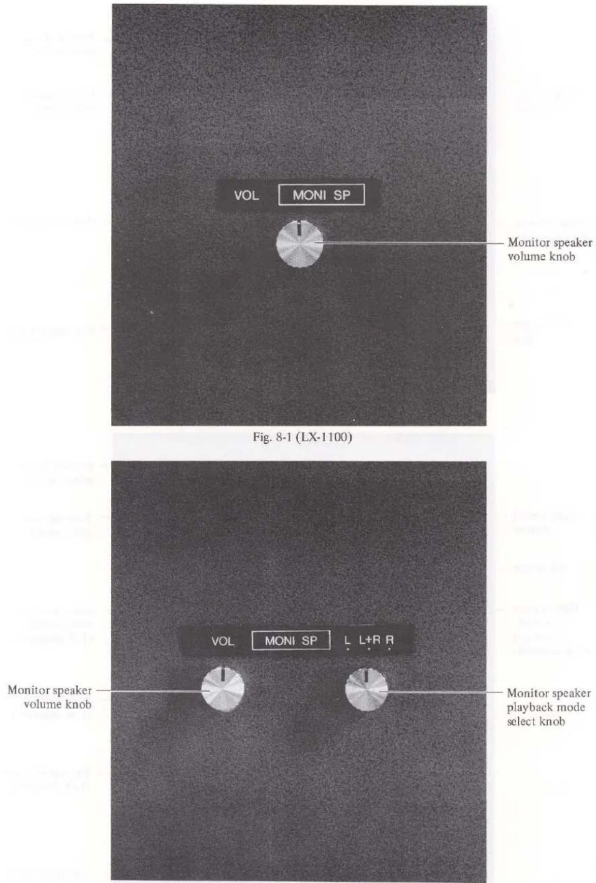
e. Monitor speaker volume knob (Fig. 8)
If this volume knob is turned clockwise, the sound from the monitor speaker is amplified.
f. Aux. output jack (Fig. 7)
The impedance is 600 ohms balanced. Two jacks are provided in LX-2200.
g. Aux. input jack (Fig. 7)
The impedance is 10 K-ohms unbalanced.
h. Volume knob for Aux input (Fig. 7)
This knob is to adjust the input level from tape recorder, etc. (By turning this knob, the level of original 16mm sound may be affected.)
i. Ext. speaker jack (Fig. 7)
The impedance is 8 ohms and maximum output is 60W....LX-1100.
Two ext. speaker jacks, with an 8 ohms impedance, are provided for maximum 60W+60W output. Connect the RH-side speaker to R jack and the LH-side speaker to L jack respectively.... LX-2200.
j. M-O select lever (Fig. 5)
This lever is used to select the mode of sound playback, either optical sound or magnetic sound.
If turned to the RH-side "O", the optical sound can be played back and if to the LH-side "M", the magnetic sound can be played back.
This switch-over operation is interlocked with the pad roller and the amplifier circuit is also automatically switched to the playback mode selected.
IMPORTANT: While this select lever is set to "M" position, the reverse projection can't be performed.
k. L/R balance control knob (Fig. 6) ..... LX-2200 only
This knob is to adjust the balance of L (left) and R (right) channel sounds while playing back in stereo mode. If the knob is turned clockwise, the sound volume of R channel will increase and the one in L channel will decrease. If turned counterclockwise, the reverse effect will be produced.
- Playback mode select knob (Fig. 6) ..... LX-2200 only
This knob is to select mode of sound playback according to the optical sound film to be run.
MONO : Plays back conventional or laser single sound track film.
STEREO : Plays back stereo or both tracks of 2-track film simultaneously.
1 : Plays back only track 1 of 2-track film.
2 : Plays back only track 2 of 2-track film.
m. Monitor speaker playback mode select knob (Fig. 8) ..... LX-2200 only
This knob is to select channel for monitor speaker.
L : Capable of monitoring the sound in L channel.
R : Capable of monitoring the sound in R channel.
L+R : Capable of monitoring both sounds in L and R channels.
n. NR (Noise Reduction) terminal (Fig. 7) ..... LX-2200 only
To minimize noise level in playback, NR (Noise Reduction) terminal is provided for the use of your noise-reducer.
When playback a sound which is recorded through a noise reducer, the use of same noise reducer in playback is recommended.
Connect the noise reducer and LX-2200 as follow:
Noise reducer's input jacks to NR output jacks of LX-2200.
Noise reducer's output jacks to NR input jacks of LX-2200.
250mmV signal is given through the projector's output jack, and a noise reducer with impedance of more than 10K ohms should be used. The projector's input jack impedance is 50K ohms, and input signal of 250mmV is ideal.
IMPORTANT: When playing back the sound without a noise reducer, be sure to leave the NR switch at OFF (down) position. If turned to ON (up) position, no sound is reproduced.
- Other Controls
a. Frame manual feed knob (Fig. 5)
This knob is used to advance the film frame one by one by hand. The reel spindle does not rotate.
b. Film gate lever (Fig. 5)
If the lever is pushed on to right, the film gate is opened.
c. Focusing knob (Fig. 5)
This knob is used to focus the image on the screen.
d. Masking knob (Fig. 5)
If this knob is turned counterclockwise, the frame is raised on the screen; if turned clockwise, the frame moves down. This device is used to eliminate the frame line appeared on the screen.
e. Tilt handle (Fig. 1)
This handle is used to tilt up or down the projector when adjusting the projection image to the screen.
If turned clockwise, the projector is allowed to tilt upward and when turned counterclockwise, it tilts downward.
f. Lamp current adjusting hole (Fig. 13)
An access opening to the lamp current adjusting rod. Use the flat-tip screwdriver for adjustment.
The lamp current is factory-adjusted so that no additional adjustment is required.
But if the adjustment is required for some reason, turn the rod clockwise to increase the current or counterclockwise to decrease it.
Be sure to make this current adjustment while the projector is set for normal projection; with the main motor running and the douser open. The lamp current applicable is 50A maximum for LX-1100 or 80A maximum for LX-2200. Take best care not to raise the current to the red marked area in the lamp ammeter. The lamp may be exploded if a current more than the above specified value is applied to the lamp.
g. Reel holding knob (Fig. 14)
When using a long-run film of more than 2400 feet, this knob is used to fix the reel to the reel spindle. When the reel holding knob is used, leave the reel lock in the raised position.
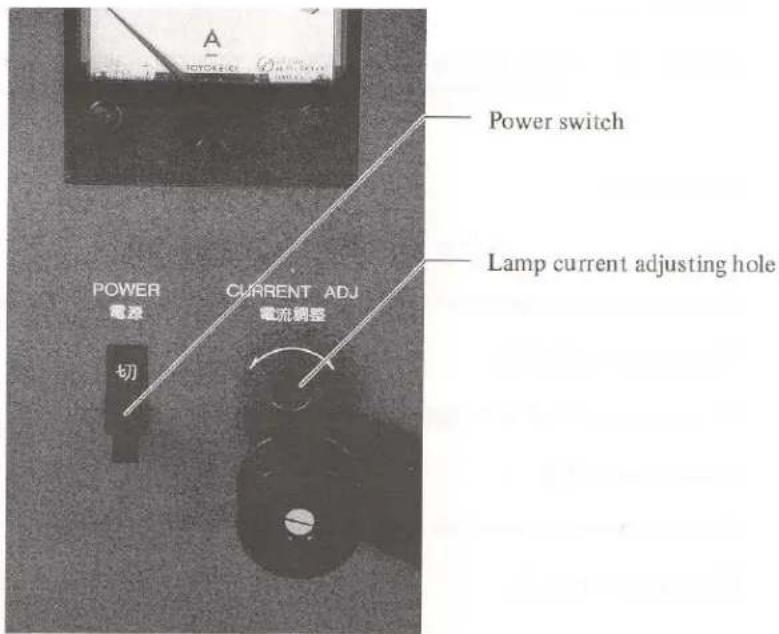
Fig. 13

Fig. 14
- Electric Bulbs
a. Projection light source
Xenon-arc lamp 1000W
b. Exciter lamp 4V-0.75A
Light source for optical sound playback scanning beam.
This lamp comes on only when the M-O lever is set at "O" position.
c. Take-up/rewind motor torque control lamps
Light source to regulate the torque of the take-up and rewind motors.
When the power switch is turned on, these lamps come on.
- Magnetic Playback System
a. Magnetic playback head
Housed inside the sound drum, this head performs the function of picking up the signals recorded on the magnetic sound track of the film.
Through the actuation of the M-O select lever, the playback head comes in contact with and off the film which is pulled taut around the sound drum. The head is fixed at the best working position so that it should not be removed and the adjusting screw should not be tampered.
b. Pad roller
When playing back the magnetic sound, this roller functions to allow the film to make a tight contact with the head. The rotating part of this roller is made of synthetic rubber.
The pad roller is operated by the M-O select lever. Be sure to leave the select lever at "O" position when the projector is not in use so that the pad roller is kept off the sound drum.
Unless otherwise, the rubber roller may be deformed, causing uneven roller rotation.
- Film Transport Mechanism
a. No. 1 Sprocket (Fig. 5)
The function of the No. 1 sprocket is to advance the film from the feed reel to the film gate.
b. No. 2 Sprocket (Fig. 5)
This sprocket leads the film, which has been driven intermittently through the film gate, onto the sound drum at a constant speed.
c. No. 3 Sprocket (Fig. 5)
This sprocket pulls taut the film which passes over the sound drum and holds back the film being wound by the take-up reel.
d. Loop restorer (Fig. 5)
Damaged film perforations and/or faulty film splices may cause the film to be flexed in the film gate, resulting a loss of film loop under the film gate.
This trouble may cause the pictures to be deranged and the film to be damaged as well. The loop restored recovers the loop loss to remedy the trouble situation.
e. Balancing stabilizer (Fig. 5)
In combination with the sound drum, two balancing stabilizer rollers are provided to accommodate any flexing in the film path; two rollers stabilize the film drive motion through their relative operating position.
f. Sound drum (Fig. 5)
The sound drum is driven at a uniform speed by means of a flywheel, performing an important function of eliminating wow and flutter in the playback sound. The magnetic playback head and photoelectric cell are housed in this sound drum.
If the sound drum axis is distorted out of center-alignment and if any mechanical shock is exerted to the high-precision-performance bearing, the sound reproduction quality will be greatly affected.
g. Tension roller (Fig. 1)
This roller absorbs the film tension variation which derives from the film take-up action, allowing the take-up motor torque to be varied proportionally so that a constant film tension can be maintained.
- Others
a. Projection lens (Fig. 5)
Standard: F1.2 f=50mm
b. Sound lens (Fig. 12)
Lens used to produce a scanning beam by focusing a light from the exciter lamp so as to create an image of the lamp filament on the film's sound track.
This lens is fixed at factory in a precise position so that it should not be tampered and moved.
c. Reflector
Large-diameter oval reflector is combined with the plane cold mirror to allow the Xenon-arc lamp to emit a spreading beam for uniform illumination without damaging the film by heat.
Don't move the reflector and/or cold mirror out of position.
VI. OPERATION PROCEDURE
With the LX-1100/LX-2200 projectors, the initial step in operating the projection is to turn on the Xenon-arc lamp and then thread the film, which is different from those of conventional projectors. Since the douser opens belatedly after the film starts, there is no risk for the film to be damaged.
- Lighting Xenon-arc Lamp
a. Turn the power switch on:
(1) Every cooling fan motor starts running.
(2) Power display lamp comes on.
(3) "STOP", "Lamp OFF" and "Douser OPEN" display lamps on the control panel are all illuminated.
(4) The take-up and rewind motors are switched on and the reel spindle are being braked.
b. When the lamp ON button is depressed, the lamp is half-illuminated immediately and the lamp display is switched from "OFF" to "ON".
Note: This projector is provided with a safety switch in the lamp ignition circuit. If the lower part of the lamphouse cover is off or not fitted snugly, the lamp won't come on.

Fig. 15
2. Film Threading
Refer to Fig. 9 for details on the film path.
Note:
a. Be sure to pass the film through the upper and lower tension rollers. Unless otherwise, there is a risk that the film may be torn when the projection is started.
b. This projector is specially equipped with film break interlock switch (roller type) to stop projector when the film breaks during projection by accident or the projection ends. Make certain that the film is properly loaded on the film break switch as per Fig. 9.
If you want to forward-run the projector without loading it with film, press and hold the film break interlock switch to the left.
c. Be certain to secure the reel with the reel holding knob when using a reel for film of more than 2400 feet.
3. Preparation before Projection
a. Setting the M-O select lever:
Set the M-O lever either to position "M" for magnetic sound film or to position "O" for optical sound film.
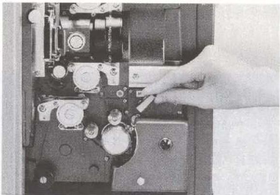
Fig. 16
b. Setting film capacity select switch:
In conformity with the capacity of the reel to be used, set the film capacity select switch to either "2400" or "6000" position.
c. It is advisable to have the sound volume and tone adjusted in advance.
d. Setting playback mode select knob: (LX-2200 only)
According to the optical sound film to be run, set the playback mode select knob either of "MONO", "STEREO", "1" or "2".
- Starting Projection
a. Depress the forward button.
The display lamp changes from "STOP" to "FWD", and the film is transported in the forward direciton. The douser will open automatically if the douser OPEN lamp is illuminated.
b. Adjust the focus and masking by use of each control knob.
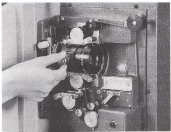

Fig. 17
c. Adjust the sound volume by turning the volume knob/amplifier switch while watching the sound level LED or listening to the sound to be reproduced through the monitor speaker.
d. Adjust the tone by means of the bass/treble control knobs.
e. Adjust the balance of L and R channels with L/R balance control knob. Refer to the sound level LED or playback sound through the monitor speaker to check the sound level. (LX-2200 only)
- Cautions during Projection
a. Pay due attention to the projected picture on the screen, sound level and tone, film transportation and taking-up conditions, lamp ammeter, machine noise, etc., during the projection for performing the projector in the best condition.
b. Don't give any impact or jolt against the projector while it is running. Keep the ventilation openings in the projector free.
- After Projection
a. When the projection comes to an end, depress the stop button.
Turn off the amplifier by turning the volume knob fully counterclockwise.
Turn off the projection lamp by depressing the lamp OFF button.
b. Rewinding the film:
As soon as the above procedure a. has been finished, set the trailing end of the film to the feed reel and depress the film rewind button. In this connection, if the Elmo Scope Lens holder is attached to the accessory shoe, pass the film around the guide roller fitted on the top of the lens holder. When the film rewinding is over, depress the film rewind button again to stop the projector.
c. Turn off the power switch after allowing the projection lamp to cool enough.
- Other Operation Hints
a. Reverse Projection:
If the M-O select lever is set at "O" position, it is possible to perform the reverse projection by depressing the reverse button.
b. Remote control projection:
Setting the remote/local select switch to "REMOTE" position will allow you to play the remote control projection.
The following operations can be controlled by means of optional remote control unit:
Forward run, Reverse run, Stop, Lamp On/Off, Douser Open/Close, Sound On/Off.
The projector can be operated by the projector's control panel with the remote/local select switch being set at either side.
The other operation procedures are similar to those of the ordinary projection. However, in case the amplifier switch on the remote control panel is turned OFF, no sound is played back even if the volume knob on the projector is fully turned clockwise.
Contrarily, if the volume knob on the projector is set at "O" position, no sound is reproduced even if the amplifier switch on the remote control panel is turned ON.
c. Changeover projection:
When changing over the projection alternately using two projectors installed side by side, proceed as follows:
(1) Turn on the projector lamp in both projectors as in the procedure described in procedure VI.1. In this case, leave the douser of the No. 2 projector close by depressing the douser CLOSE button. The following display lamps come on.
No. 1 Projector : Lamp ON, Douser OPEN, STOP. No. 2 Projector : Lamp ON, Douser CLOSE, STOP.
(2) Load the No. 1 projector with film according to procedure VI. 2.
(3) Set up the controls of the No. 1 projector according to the procedure VI. 3.
(4) Start the No. 1 projector according to the procedure VI. 4.
(5) Load the No. 2 projector with film according to the procedure VI.2. and set up the controls of the No. 2 projector according to the procedure VI.3. Adjust the sound volume and tone in advance.
(6) When the first sign for changeover is noticed on the screen, depress the changeover button of the No. 1 projector. With the display lamp on, the No. 2 projector will start with the douser being closed. The "FWD" lamp on the No. 2 projector comes on and the "STOP" lamp goes out.
(7) When the second sign is noticed on the screen, depress the douser CLOSE button on the No. 1 projector. The douser of the No. 2 projector is opened and the douser of the No. 1 projector is closed. At the same time, the amplifier on the No. 2 projector is switched on and the No. 1 amplifier is turned off. Thus the projection is changed over from No. 1 projector to No. 2 projector.
(8) Depress the stop button on the No. 1 projector as soon as the film on it has been rewound fully. The "STOP" lamp on the No. 1 projector comes on. When the "FWD" lamp goes out, the "CHANGE-OVER" lamp goes out at the same time.
(9) Rewind the film according to procedure VI.6.
VII. MAINTENANCE HINTS
- Cleaning Projector
a. Aperture plate and pressure plate
Clean the aperture and pressure plates every time before starting the projection.
Open the film gate. Pinching the plate holder, raise and pull it toward yourself to remove the pressure plate. When removing the pressure plate, keep the sending claw in a retracted position by turning the frame manual feed knob.
(1) Wipe dust off the aperture plate with the supplied brush. (Fig. 18)
(2) Clean the pressure plate carefully using a soft cloth.
(3) A film residue adhered on the pressure plate will scratch the film, so such a residue deposit must be wiped off completely by rubbing off with the brush.


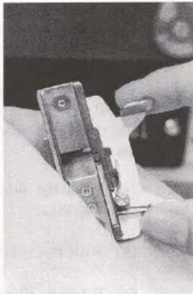
Fig. 18
b. Projection lens
Dismount the projection lens, pulling on the focusing knob toward yourself.
Clean the projection lens carefully using a lens brush, soft cloth or lens cleaner. Don't rub or touch the lens with finger.
When installing back the projection lens in position, insert it as far as it will go while pulling on the focusing knob toward yourself.
Then, pull back the lens until it clicks. This means the tip of the focusing knob is set in the groove on the lens housing. Make sure that the lens moves in and out smoothly by turning the focusing knob.
- Lubrication
The intermittent film transportation mechanism is lubricated by a felt sump containing sufficient oil in addition to the high-performance oil-sealed bearing so that no frequent oiling thereto is necessary.
However, on the occasion of regular inspection or repair work, supply four or five drops of Elmo Special Oil (option) through the oil hole.
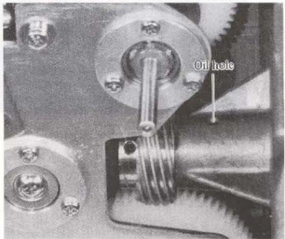
3. Replacing Major Component Parts
a. Xenon-arc lamp
This projector uses an exclusively-designed 1000W Xenon-arc lamp. The service life of this lamp is extremely long compared with that of conventional lamp but the illumination performance is deteriorated after a long-time use.
For replacing, be sure to contact the authorized Elmo service center.
Note: The projector incorporates a timer counting the actual length of lamp illumination hours. The timer is located beneath the power switch (Fig. 1).
b. Exciter lamp (Fig. 12)
(1) Remove the exciter lamp cover.
(2) Push the head of the exciter lamp down a little bit and turn it counterclockwise to remove. The metal flange of the lamp is provided with three fitting holes with each hole-to-hole pitch differently spaced so that the lamp can be fitted into the receptacle very easily without mistake. Push the lamp downward and turn it clockwise as far as it will go when putting a new lamp in position.
(3) Whenever replacing the exciter lamp with new one, attempt to play back a sound by running an optical sound film. This projector features a specifically designed sound reproduction system. In order to let the system to make a maximum performance, adjust the exciter lamp position precisely in the following procedure.
(a) Load the projector with the supplied test film for exciter lamp position adjustment as shown in Fig. 20.
(b) With the volume knob set at a middle position, run the projector and check the sound level LED.
(c) If two or three of LEDs come on, it means the exciter lamp is properly set up.
(d) Unless otherwise, it means the exciter lamp is set up out of correct position.

Fig. 20
Loosen two setscrews on the side of the socket holder.
Adjust the vertical level of the lamp and the right angle of the filament to the optic axis so that a maximum number of level display LEDs can glow.
Adjustment of the exciter lamp position (LX-2200 only):
If the numbers of glowing display LEDs for L and R channels are extremely different even with L/R balance control knob in the middle position, loosen the socket holder setscrews and move the holder in and out (or away from or toward yourself). Fix the socket holder in such a position where the glowing display LEDs for both channels are well balanced in number.
c. Fuses
(1) Power fuse:
Open the projector rear cover and take out the 5A fuse out of the fuseholder near the transformer.
(2) Amplifier fuses:
The amplifier fuses are located on the amplifier printed circuit board. Open the projector rear cover for access to these fuses.
5A fuse ..... 2 pcs.
3A fuse ..... 1 pcs.
Besides 2 pcs. of 5A and 1 pce. of 3A fuse, 2 pcs. of 2A fuse are used for LX-2200 only.

Fig. 22-1 (LX-1100)

Fig. 22-2 (LX-2200)
(3) Control circuit fuse:
A 3A fuse is installed in the control circuit PC board. Open the projector rear cover for access to this fuse. Spare fuse is provided on the inner side of the rear cover.
(4) Take-up/Rewind motor torque control lamps:
Remove the pedestal rear cover for access to the take-up motor torque control lamp and the feed reel arm rear cover to the rewind motor torque control lamp, respectively. Take out the lamp together with the socket when replacing the lamp. Use 12V 3.4W swan type bulb.

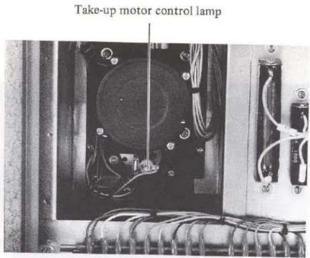
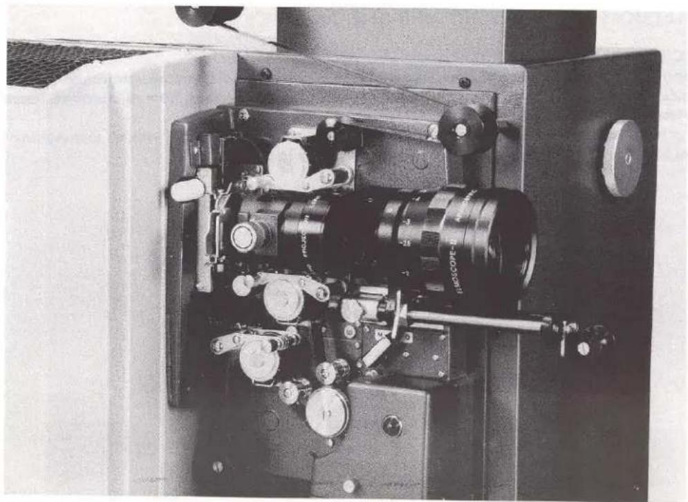
VIII. ELMO SCOPE LENS HOLDER (Fig. 24)
LX-1100/LX-2200 are equipped with exclusive Elmo Scope Lens Holder.
With use of an optional Elmo Scope Lens, it's possible to play a 16mm cinemascope projection.
This holder attachment is capable of accommodating a wide range of lenses; from the standard 50mm lens up to a zoom lens with long lens barrel.
A film guide roller is provided on the holder so that the film can be rewound without dismounting the holder. This lens holder is also designed to support a long-barrel zoom lens.
Elmo Scope Lens with 50mm Standard Lens

Elmo Scope Lens with Zoom Lens
Fig. 24
ELMO

ELMO CO., LTD.
Elmo Mfg. Corp
70 New Hyde Park Road.
New Hyde Park,
NY 11040-9980,
U.S.A.
Tel. 516-775-3200
Fax. 516-775-3297
21720 Nordhoff St.
Chatsworth.
CA 91311-5826.
U.S.A
Tel. 818-346-4500
Fax. 818-998-4186
6-14, Meizen-cho,
Mizuho-ku, Nagoya 467, Japan
Elmo Canada Mfg. Corp.
44 West Drive Brampton,
Ontario, L6T 3T6.
Canada
Tel. 905-453-7880
Fax. 905-453-2391
Elmo (Europe) G.m.b.H.
Karl-Rudolf-Str. 178
40215 Düsseldorf.
Germany
Tel. 0211-376051-53
Fax 0211-376630
- ELMO
- 16MM XENON-ARC LAMP SOUND PROJECTORS
- LX-1100/LX-2200
- INSTRUCTION MANUAL
- CONTENTS
- INTRODUCTION
- COMPONENTS
- NOMENCLATURE
- FUNCTION OF MAJOR COMPONENT PARTS
- PROJECTION CONTROL SWITCHES
- POWER SWITCH (FIG. 1)
- LAMP ON/OFF BUTTONS (FIG. 6)
- FORWARD BUTTON (FIG. 6)
- STOP BUTTON (FIG. 6)
- REVERSE BUTTON (FIG. 6)
- DOUSER OPEN/CLOSE BUTTONS (FIG. 6)
- OPERATION PROCEDURE
- FILM THREADING
- NOTE
- PREPARATION BEFORE PROJECTION
- MAINTENANCE HINTS
- REPLACING MAJOR COMPONENT PARTS
- XENON-ARC LAMP
- EXCITER LAMP (FIG. 12)
- FUSES
- ELMO SCOPE LENS HOLDER (FIG. 24)
- ELMO CO., LTD
- ELMO MFG. CORP
- ELMO CANADA MFG. CORP
- ELMO (EUROPE) G.M.B.H
Marque : Elmo
Modèle : LX-2200
Catégorie : Projecteur de film