85145126 - Climatiseur HAGER - Notice d'utilisation et mode d'emploi gratuit
Retrouvez gratuitement la notice de l'appareil 85145126 HAGER au format PDF.


| Type de produit | Disjoncteur modulaire |
| Marque | Hager |
| Modèle | 85145126 |
| Tension nominale | 230/400 V AC |
| Courant nominal | 10 A |
| Pouvoir de coupure | 6 kA |
| Nombre de pôles | 1P |
| Courbe de déclenchement | C |
| Dimensions (L x H x P) | 18 x 85 x 70 mm |
| Poids | 150 g |
| Alimentation | Réseau électrique AC |
| Fonctions principales | Protection contre les surcharges et les courts-circuits |
| Entretien et nettoyage | Nettoyer avec un chiffon sec, ne pas utiliser de produits chimiques |
| Sécurité | Installation par un électricien qualifié, respecter les normes en vigueur |
| Pièces détachées et réparabilité | Non réparable, remplacer l'appareil en cas de défaut |
| Informations générales | Norme NF C 61-140, usage intérieur |
| Indice de protection | IP20 |
| Température de fonctionnement | -5 °C à +40 °C |
| Type de fixation | Montage sur rail DIN |
| Matériau du boîtier | Plastique auto-extinguible |
| Capacité de raccordement | 1 à 25 mm² |
| Nombre de cycles électriques | 10 000 |
FOIRE AUX QUESTIONS - 85145126 HAGER
Questions des utilisateurs sur 85145126 HAGER
0 question sur cet appareil. Repondez a celles que vous connaissez ou posez la votre.
Poser une nouvelle question sur cet appareil
Téléchargez la notice de votre Climatiseur au format PDF gratuitement ! Retrouvez votre notice 85145126 - HAGER et reprennez votre appareil électronique en main. Sur cette page sont publiés tous les documents nécessaires à l'utilisation de votre appareil 85145126 de la marque HAGER.
MODE D'EMPLOI 85145126 HAGER
KNX radio button 1gang quicklink
KNX radio button 2gang quicklink KNX radio button 4gang quicklink
2.1.1.1.
Safety instructions
Electrical equipment must only be installed and assembled by a qualified electrician in accord-
ance with the relevant installation standards, regulations, directives and safety and accident
prevention directives of the country.
Failure to comply with these instructions may result in damage to the device, fi re or other haz-
ards. The radio transmission is not suitable for safety.
The radio transmissio or alarm applications.
These instructions are an integral component of
the product and must be retained by the end user
Design and layout of the device

Fig. 1: Design and layout of the device
(1) Insert (see "Accessories", not in
scope of delivery) (2). Frame (not included
(2) Frame (not included) (3) Application module 1
(4) Module retaining screw
(not for Berker R.1/R.3/R.8)
(5) Design cover button 1gang
(6) 2gang button or 4gang button design cover
(7) Interface between insert/application module
Function
System information
This device is a product of the quicklink system, in
which installation devices communicate via radio signals.
quicklin
the function-related connection between transmitters and receivers is set on the device through buttons.
and receivers is set on the device through buttons and displays without further tools.
All devices confi gurable by quicklink can be operated together in one system.
This device complies with EU Directive 2014/53/EU.
The declaration of conformity and further system information can be accessed at hager.com
The device may be operated in all EU and EFTA
states (excluding Switzerland and Liechtenstein).
Correct use
- For operation and remote control on a switch
insert, on a dimmer insert or on a power supply for KNX radio application modules.
- The device has been designed for smaller appli-
cations, in which a maximum of 20 devices are allocated
- Only suitable for use in indoor areas with no drip
and no spray of water
The quicklink configuration of the devices must only be carried out by qualified electricians.
Product characteristics
Product characteristics Functions for samples or
- Functions for remote control, scenes, control circuits via radio signals
- LED display of the compatibility of the insert/ap-
plication module - Savings of switch on brightness level if operated
- Saving of switch-on brightness level if operated on a dimmer insert
- Option for load setting during operation with uni-
Operation
Operating concept
The operation of the top or bottom push-button op-
eration area is validated differently for each button. Simultaneous pressing of top and bottom push-but-
ton operation areas triggers special functions.
Operation on a switch insert
Load status Operation button, factory setting Switch insert
OFF Press top or bottom Switch ON load.
load.
2.6 (100%)
Operation on a dimmer insert
Dimming Operation button, Dimmer insert
status factory setting OFF Short press on top or bottom Switch ON with guard
OFF Short press on top of bottom switch ON with saved switch-on brightness level.
ON Short press on top or bottom Switching OFF.
ON Press top and bottom Save brightness as switch-on brightness-level.
simultaneously > 5 s As confirmation, the light switches OFF briefly and ON again.
In the delivery condition, the maximum brightness is saved as the switch-on brightness level
ON/OFF Long press on top Dimming to maximum brightness-level
ON Long press on bottom Dimming to minimum brightness-level
OFF Long press on bottom Switching on with minimum brightness-level
Table 2: Operation on a dimmer insert
Operation via extension unit, push-button, NO contact
Dimming Operation Switch insert Dimmer insert with extension unit input
status push-button
OFF Press < 0.4 s Switch ON Switch ON with saved switch-on brightness-level ON Press < 0.4 s Switch ON with saved switch-on brightness-level
ON Press < 0.4 s Switch OFF Switch off ON Press ≥ 0.4 s Switch OFF Dimming to minimum/maximum brightness-level
with alternating direction
ss > 0.4 s Switch ON Dimming from minimum to max
ness-level
Table 3: Operation via extension unit, push-button, NO contact
The switch-on brightness-level cannot be saved on an extension unit push-button.
Operation on a power supply for KNY radio
operation on a pow application module
The push-buttons are freely confi gurable; operation
is dependent on the configuration (Table 7)
Settings
Setting the load
If the switching/dimming of the universal inserts is
not as desired after commissioning the load may need to be re-set
A load setting is required each time the load is
A load set changed.
■ Switch off load.
■ Press button top and bottom
for more than 10 seconds.
The connected load fl ashes once. The device is in selection mode.
[1] If no further actions are performed within the next
10 seconds, the dimmer switches to normal oper-
ab
■ Brief y press the bottom button repeatedly to activate the desired setting mode.
▶ See Table 4a / 4b
i Information for electric
For the version labelling of
insert, see packaging label or sticker on the back of the housing.
Adjusting the load for KNX radio button 1gang or 4gang on a universal switch or dimmer insert
1gang from Version R1.2
| Press bottom button | Setting mode | Duration and confirmation of the load setting |
| [1] The light to confirm the load features at 50% brightness. | ||
| 1 x | Load factory setting | Settings duration: approx. 30 sec. [2] Load switching/dimming phases may occur during the automatic settings process. The load frames one last time as a confirmation and then goes out. The device returns to normal operation. |
| 2 x | LED mode 1 (phase cut-on) | After approx. 5 sec., the load flakes times as a confirmation and then goes out. The device returns to normal operation. |
| 3 x | LED mode 2 (phase cut-on) | Settings duration: ± 50 sec. [1] Load switching/dimming phases may occur during the automatic settings process. Finally, the load flakes three times as a confirmation and then goes out. The device returns to normal operation. |
| 4 x | Fine setting of minimum brightness | 5 predef red minimum brightness levels ± 25 sec, each, run through repeatedly (3 runs). ■ As soon as the connected load shows a satisfying minimum brightness, confn it by quickly pressing the bottom button. After approx. 5 sec., the load flakes four times as a confirmation and remains switched on (50% brightness). The device returns to normal operation. |
Table 4a
Adjusting the load on a universal switch or dimmer insert up to Version R1.1
| Briefy press the button | Setting mode | Confirrimation of the load setting | Information for use |
| 1 x | Load fi ne-setting | Load fi ashes 1 x after approx. 30 x and changes to normal operation | Not suitable for chronic loads (e.g. incandescent, HV halogen lamps), use factory load setting.If the load fi ne-setting does not bring any improvement for energy-saving lamps or 230 V LED lamps on the energy-saving lamp fi ne-setting or 230 V LED lamp universal setting. The load fi ne-setting is not available on 2qng universal inserts. |
| 2 x | Load factory setting | Load fi ashes 2 x after approx. 6 x and changes to normal operation | |
| 3 x | Energy-saving lamp fi ne-setting in phase culn | Load fi ashes 3 x after approx. 30 x and changes to normal operation | Energy-saving lamps are switched on at a brightness level of at least 50% in order to ensure the process. |
| 4 x | 230 V LED lamp universal setting in phase culn-on or phase culn-out | Load fi ashes 4 x after approx. 5 x and changes to normal operation | For connected dimmable 230 V LED lamps the dimming principle and the optimal switch-on brightness level is set automatically. |
| For all setting modes | Load fi ashes 5 x | The selected setting mode is not supported by the insert. |
Table 4b
Information for electricians
Overview of the operating elements beneath the design cover

Figure 2a: Operating elements of the 1gang radio
button
(11)
1
[Non-Text]
(2)
} || φ < ○—○ | φ || }
3.5%
x,y = ( x - 1) x,y = ( x - 2)
(8):
(1) 12 (2) 13 (3) 14 (4)
52
2
1
(二)
2014年1月1日
- 0.15%
(9) (10)
(2) (14)
Figure 2b: Operating elements of the 2 and 4gang
radio button
(8) Press-activation points of the push-button
operation area
(9) fct button with fct LED
(10) cfg button with cfg LED
(11) fct2 button with fct2 | F
(11) 102 button with 102 LED
Installation
1.2 报告期末股东总数
Selecting installation location
A minimum distance between the transmitter and
corresponding receiver of about 1 m must be main
tained.
A minimum distance to electronic devices which emit
high frequency signals such as computers, electronic
transformers or microwave devices of approx. 0.5 m
must be maintained.
Mounting on or close to metal surfaces may cause
impairment of the function.
Take material penetration into account. The range of the system can be optimised by selecting the best possible mounting location:
| Material | Degree of material penetration |
| Wood, plaster, plaster-board, uncoated glass | approx. 90 % |
| Brick, press boards | approx. 70 % |
| Reinforced concrete, underfior heating | approx. 30 % |
| Metal, metal grids, aluminium laminates, coated glass | approx. 10 % |
| Rain, snow | approx. 1 _ 40 % |
Table 5: Material penetration
Table 6. Maternal por
Mounting the device (Figure 1)
The insert is installed (see operating instructions for
the insert).
■ Attach the application module (3) together with
frame (2) to a suitable insert (1) and establish a
connection between insert and the application
module via the plug-in interface (7)
As soon as voltage is supplied to the button, the
Fig LED (Figure 2, 10) indicates whether the but-
ton and the insert are compatible with each other
| cfg LED display | Meaning |
| LED # ashes green for 5 s | Compatible |
| LED # ashes red for 5 s | Not compatible |
| LED # ashes orange for 5 s | Compatible, but not confi gured to each other. For a new con- fli guration, the application mod- ule must be reset to the factory setting. |
■ If required/included use module retaining screw
[Non-Text]
- Click the design cover (5 or 6) into place on appli-
cation module (3)
If a configuration needs to be made or settings
need to be
afterwards.
Insert/application module combinations and
operation in the factory setting
Depending on the insert used, in factory setting
The radio button has the following function for local
operation (Table 6).
Operating and assembly
instructions

Berker
[Non-Text]
KNX radio button 1gang quicklink
Order No. 8514 51
KNX radio button 2gang quicklink
Order no. 8514 61 ..
KNX radio button 4gang quicklink
Order no. 8564 81
[Non-Text]
(EN)
-
Berker GmbH & Co. KG Zum Gunterstal
vastel, Germany
Tel: +49 6842 945.0
Fax: +49 6842 945 4625
e-mail: info@berker.de
-
www.berker.com

Berker
04/2022 6LE105203D
[Non-Text]
[Non-Text]
[Non-Text]
[Non-Text]
[Non-Text]
[Non-Text]
[Non-Text]
[Non-Text]
[Non-Text]
[Non-Text]
[Non-Text]
[Non-Text]
[Non-Text]
[Non-Text]
[Non-Text]
[Non-Text]
[Non-Text]
| KNX radio button 1gang | KNX radio button 2gang | KNX radio button 4gang | |||
| Switch insert 1gang | _0H | --- | --- | _3H | (I_W) |
| Switch insert 2gang | -- | _0H | _0H | _3H | _3H |
| Dimmer insert 1gang | ### | --- | --- | ### | (I_W) |
| Dimmer insert 2gang | -- | ### | ### | ### | ### |
| Power supply | (I_W) | (I_W) | (I_W) | (I_W) | (I_W) |
on off Switching (see operation on a switch insert)
Dimming (see operation on a dimmer insert)
- Not to be combined
(###) Transmitter command freely configurable (see Configuration of radio button as transmitter)
Table 6: Button operation in factory setting
KNX radio timer quicklink
The radio configuration sets up the functional connection between commanding (transmitters) and function-executing (receivers) radio components. Thus, central unit, group, extension unit and time controls can, for example, be realised in a wireless manner.
The following can be configured: - The local operation of the load connected to the insert
- Radio commands to control other receivers
- Functions which are executed when the radio
commands are received
The top and bottom push-button can be configured differently.
For configuration by means of Hager connection
device TX100 or ETS, additional functions are
available (see operating instructions for TX100 or application description for ETS)
application description for ETS)
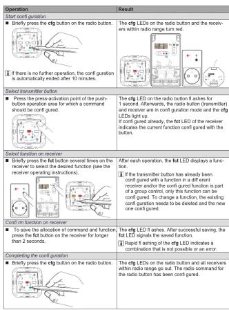
Confi guration of KNX radio button as a receiver Confi guration to control the load connected to the insert (Table 7)
- via reception of a radio command
- via local operation
Local operation is a function that is pre-config
ured at the factory and can be changed. As an example, the confl guration with a wall trans- mitter and the radio button as receiver is described below (Table 8).
The button design cover is not attached.
Configuration of KNX radio button as a
transmitter
If the radio button is operated as a transmitter, it can support the following functions for the receivers. The details of the function can vary, depending on the receiver being used:
on ON/OFF 1-push-button operation
on
ON OFF OFF
ON/OFF dim URIDOWN 1-push-button
operation
+ ON/OFF, dim U
- ON/OFF, dim DOWN
■1 Scene 1
Scene 2
Timer
NO contact (contact length)
▲ Move UP, stop
■ Move DOWN stop
- MORE DOWN, stop As an example, the configuration of the radio button
As an example, the configuration of the radio button with receivers, for which the supported displays.
occur through the cfg LED and fct LED, is described
here (Table 9). Diff ering confl guration displays, such
as for receivers with display, can be found in the receiver operating instructions.
Receiver operating instruction
Deleting a confi guration
To delete a configured receiver or the local operation, perform the configuration again.
tion, perform the configuration again
■ Start configuration (see Confi guration of radio button as a receiver)
- Select transmitters
■ Select transmitter button. ■ Select function on receive
■ Select function on Acumin. On the receiver, select the Delete function and confirm function
on the receiver.
■ Completing the configuration: Briefly press the
cfg button on the transmitter.
Confi guration of group functions
By means of a group function, one transmitter controls several receivers. To do so, the same function must be configured on all receivers.
■ Start conti guration (see Confl guration of radio button as a receiver)
■ Select transmission buffer
- Select transmittal buffer - Select function on receipt
■ Select function of receiver. Select the group function as described on each receiver to be
function as described on exam receiver to be included and confirm function on the receive
■ Completing the configuration: Briefly press the
cfg button on the transmitter
Configuration of scenes
Individual settings for lighting and the position of blinds can be combined into scenes. Two different scenes can be created via quicklink and called up by pressing a button on the transmitter. A scene is created by confi guring a push-button operation area of a transmitter (radio command) in the corresponding receivers with the Scene function (Table 7).
■ Start configuration.
■ Select transmitter button: Select the button for
the Scene command.
■ Select function on receiver: Select the Scene
function as described on each receiver to be included and confirm function on the receiver
■ Completing the configuration Briefly prone 1
■ Completing the configuration. Briefly press the cfg button on the transmitter.
Changing/saving scenes
Switching, dimming and blind statuses of the receiv-
ers in a scene can be changed and saved.
■ The load status can be configured locally or by
remote control on the receivers integrated into
the scene, e.g. light 1 = 60 % brightness level,
light 2 = 40 % brightness level, blind down.
- Keep the transmitter button belonging to the
born gured scene command pressed for more than 5 seconds.
than 5 seconds.
A brief status changeover of the receivers signals the successful rating of the score.
the successful saving of the scene
[Non-Text]
1 x 1 ash: Scene changing and saving 2 x 2 ash: Scene showing workers
2 X finishes. Scene changing blocks
■ Press selling
Setting.
The settia
pressed.
■ To accept the selected setting time, keep the fact
button pressed for more than 2 seconds.
■ Completing the configuration: Briefly press the
ctg button on the transmitter
Locking/unlocking scene changes
To prevent unwanted changes to a scene, the
changing of the scene can be locked.
■ Start configuration
■ Select transmitter button: Select the button for
the Scene command.
■ Select function on receiver. If the function Scan
1 or Scene 2 is displayed by the fct LED flashin
green, hold down the fct button on the receiv-
er for longer than 5 seconds until the cfg LED
fl ashes briefl y.
Then, the fct LED shows the currently set state
by flashing:
1 x flash: Scene changing and savin
2 x fl ashes; Scene changing blocked
■ Press the fct button and select the desired
setting.
The set
pressed. ■ During the closing, the 1st LED installed is switch-on time (Table 10) for orientation.
■ To accept the selected setting time, keep the fact ■ To accept the selected switch-on time, press the
button pressed for more than 2 seconds. To accept the selected button on time, press the fct button for longer than 2 seconds.
■ Completing the configuration: Briefly press the ■ Completing the configuration: Briefly press the
cfg button on the transmitter. Canceling the configuration. Here you press the cfg button on the transmitter.
Setting the switch-on time for the timer
The switch-on time on the receiver can be set in
stages for the Timer function. The factory setting is
3 min.
■ Start configuration.
■ Select transmitter button: Select the button with
the timer.
■ Select function on receiver: If the Timer function
is displayed by the fct LED flashing red (Table
7), hold down the fot button on the receiver for
longer than 5 seconds, until the cfg LED fl ashe
brief y.
The flashing fct LED indicates the currently set
switch-on time - 5 x for factory setting (Table 10
■ Press the fct button.
Each short press of the fct button increases the
switch-on time by one step.
During the setting, the first LED indicates th
■ During the cooling, the Net LED indicators switch-on time (Table 10) for orientation.
■ To accept the selected switch-on time, press the
- To accept the selected switch on time, press the fct button for longer than 2 seconds.
■ Completing the configuration: Brief x press the
- Complicating the configuration. Briefly predicts the cfg button on the transmitter.

Table 10: Settable switch-on times
Technical data
Transmission frequency
Transmission power
Radio protocol
Radio protocol
Power supply
表决结果:9票,反对0票,弃权0票。
quicklink logic functions
2.2.1 2017年1月1日
Receiver category
Transmitter duty cycle
Degree of protection
Relative humidity
,
Ambient temperature
Storage/transport lamp
Storage/transport tempe
Mounting orientation
[Non-Text]
Accessories
Inserts for KNY radio
Inserts for KNX Radio
Relay insert
Universal switch insert
Push-button dimmer 1g
Push-button dimmer co
Power supply for KNY, p
Power supply for RNA application module
- Investments for ISNPV and the
Inserts for KNX Radio
Universal switch insert 2
Universal push-button d
Power supply for KNX
application module
Inserts for KNY radio
Inserts for KNX Radio
Relay Insert
Universal switch insert
Push-button dimmer 1g
Push-button dimmer co
Universal switch insert 2
Universal push-button d
Diversified plan button
Power supply for KNA in application module
application module
Warranty
We reserve the right to
changes to the product
progress.
Our products are under
of the statutory provisions.
If you have a warranty claim
point of sale.
| fct LED display | Confl configurable functions | Function resulting from transmitter operation, notes | ||
| On switch insert | On dimmer insert | |||
| on | ON/OFF | ON | Off, dim UP DOWN | Short button-press: Switch ON/OFFLong button-press: Dimming, reverse dimming direction per actuation |
| on | ON | + | ON, down | Short button-press: Switch ONLong button-press: Dim UP to maximum brightness |
| off | OFF | = | OFF, dim DOWN | Short button-press: Switch OFFLong button-press: Dim DOWN to minimum brightness |
| Scene 1 | Receiver is allocated to a scene due to the confuration of the function | |||
| Scene 2 | Short button-press: Short button-press: Recall the following connections load for the scene | |||
| Timer | Switch ON for the set switch-on time | |||
| NO contact(contact duration) | Switch ON when the switching contact is closedSwitch OFF when the switching contact is opened | |||
| Cancel | No functionAssignment to transmitter is deleted | |||
Table 7: Configurable functions
Table 8: Confi gure function for the KNX radio button (example with KNX radio wall-transmitter)
Table 9: Configuration of KNX radio button as a transmitter
| fct LED display | Confl configurable functions | Function resulting from transmitter operation, notes | ||
| On switch insert | On dimmer insert | |||
| on | ON/OFF | ON | Off, dim UP DOWN | Short button-press: Switch ON/OFFLong button-press: Dimming, reverse dimming direction per actuation |
| on | ON | + | ON, down | Short button-press: Switch ONLong button-press: Dim UP to maximum brightness |
| off | OFF | = | OFF, dim DOWN | Short button-press: Switch OFFLong button-press: Dim DOWN to minimum brightness |
| Scene 1 | Receiver is allocated to a scene due to the confuration of the function | |||
| Scene 2 | Short button-press: Short button-press: Recall the following connections load for the scene | |||
| Timer | Switch ON for the set switch-on time | |||
| NO contact(contact duration) | Switch ON when the switching contact is closedSwitch OFF when the switching contact is opened | |||
| Cancel | No functionAssignment to transmitter is deleted | |||


p. 107-425



- KNX radio timer quicklink
- Configuration of KNX radio button as a
- transmitter
- Confi guration of group functions
- Configuration of scenes
- Changing/saving scenes
- Locking/unlocking scene changes
- Setting the switch-on time for the timer
- Technical data
- Transmission frequency
- Accessories
- Inserts for KNY radio
- Warranty
Marque : HAGER
Modèle : 85145126
Catégorie : Climatiseur