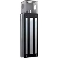
MG1300 - Serrure électrique LiftMaster - Notice d'utilisation et mode d'emploi gratuit
Retrouvez gratuitement la notice de l'appareil MG1300 LiftMaster au format PDF.


| Type de produit | Ouvre-porte de garage |
| Marque | LiftMaster |
| Modèle | MG1300 |
| Dimensions (L x l x H) | 30 x 25 x 20 cm |
| Poids | 5 kg |
| Alimentation | 120 V AC, 60 Hz |
| Puissance du moteur | 1/2 HP |
| Type d'entraînement | Chaîne ou courroie |
| Fonctions principales | Ouverture et fermeture automatique, télécommande, sécurité anti-écrasement |
| Nombre de télécommandes incluses | 2 |
| Portée de la télécommande | Jusqu'à 30 mètres |
| Sécurité | Capteur d'obstacle, inversion automatique, verrouillage manuel |
| Entretien et nettoyage | Essuyer avec un chiffon humide, lubrifier les rails une fois par an |
| Pièces détachées et réparabilité | Moteur, télécommandes, capteurs, rails, courroie/chaîne |
| Garantie | 2 ans |
| Informations générales | Compatible avec les systèmes LiftMaster, installation sur portes sectionnelles ou basculantes |
FOIRE AUX QUESTIONS - MG1300 LiftMaster
Questions des utilisateurs sur MG1300 LiftMaster
0 question sur cet appareil. Repondez a celles que vous connaissez ou posez la votre.
Poser une nouvelle question sur cet appareil
Téléchargez la notice de votre Serrure électrique au format PDF gratuitement ! Retrouvez votre notice MG1300 - LiftMaster et reprennez votre appareil électronique en main. Sur cette page sont publiés tous les documents nécessaires à l'utilisation de votre appareil MG1300 de la marque LiftMaster.
MODE D'EMPLOI MG1300 LiftMaster
LiftMaster®
WIRING & SPECIFICATIONS
Model MG 1300
WIRING INSTRUCTIONS
Wiring 12 Vdc or 24 Vdc Transormer


Do Not Use Wire
Smaller than
22 AWG
HARDWARE LIST AND SPECIFICATIONS

Housing: Stainless Steel
Junction Box: Steel
Magnet Plate: Steel
Plating: Zinc Clear
Power Supply
12 Vdc Supply:
Transformer: input 120 Vac
Output: 7.2 VA 12 Vdc @ 600 mA
24 Vdc Supply (Not provided):
Transformer: input 120 Vac
Output: 14.4 VA 24 Vdc @ 600 mA
Current draw
250 mA @ 24 V, 500 mA @ 12 V 600 mA
- If power supply is 12 Vdc and wire is 50 ft. use 18 AWG, if wire is 150 ft. use 14 AWG
- If power supply is 24 Vdc and wire is 50 ft use 22 AWG, if wire is 150 ft. use 18 AWG

WARNING: This product can expose you to chemicals including lead, which are known to the State of California to cause cancer or birth defects or other reproductive harm. For more information go to www.P65Warnings.ca.gov
HANDLING: The magnetic lock, junction box and magnet plate are ruggedly constructed and designed to provide years of trouble-free service. Care must be taken, however, during installation and during actual use so that the magnet face and magnet plate face are free of dirt, rust, burrs, paint, or any other obstruction which may interfere with the magnet and magnet plate making good contact.

MOUNTING INSTALLATION
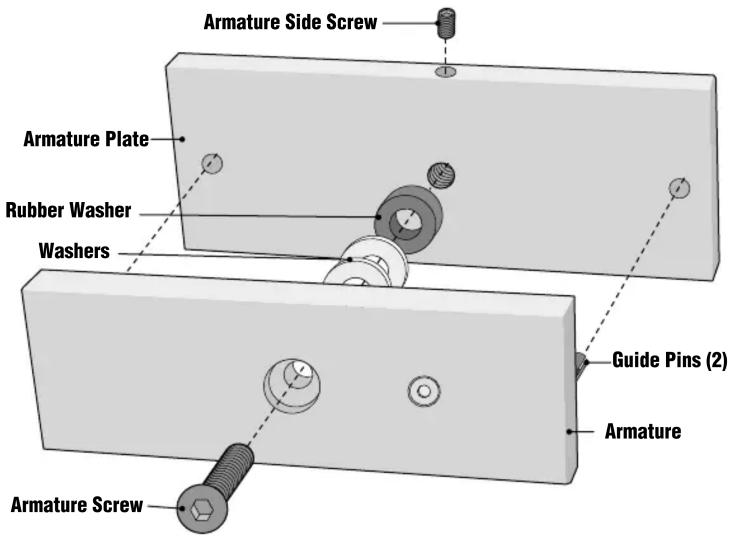
① Position the magnetic lock with armature plate at desired location and tack weld the magnetic lock plate to the gate post. Do not fully weld or you will burn the wire or lock.
② Tack weld armature plate to gate. Again, Do not fully weld or you will burn the rubber pieces.
③ Remove the armature plate with rubber washer and magnetic lock from the junction box and fully weld the plates.
④ After it cools-off, reassemble magnetic lock and armature with the rubber washer.
![graph LR A["POST"] --> B["Welding"] B --> C["Magnetic Lock Mounting Screws"] C --> D["Magnetic Lock Plate"] D --> E["Armature Screw"] E --> F["Armature Plate"] F --> G["Armature Washer"] G --> H["Armature Allen Screw"] H --> I["Guide Pins"] I --> J["Welding"] J --> K["Post"] L["Junction Box"] --> M[…](/content/2026/06/1403721/images/53dd7a8f1d543e12127c20a867ba167b60096f32c503702ea4fff1e3b124af96.jpg)
For Technical Support: www.liftmaster.com 1-800-528-2806
Marque : LiftMaster
Modèle : MG1300
Catégorie : Serrure électrique