ZSO 181 - Antenne satellite KATHREIN - Notice d'utilisation et mode d'emploi gratuit
Retrouvez gratuitement la notice de l'appareil ZSO 181 KATHREIN au format PDF.


| Type de produit | Antenne satellite parabolique |
| Marque | Kathrein |
| Modèle | ZSO 181 |
| Diamètre de la parabole | 75 cm (estimation) |
| Matériau de la parabole | Acier peint ou aluminium |
| Poids | Environ 4 kg |
| Alimentation | Passive (aucune alimentation externe requise) |
| Type de LNB | LNB universel (bande Ku) |
| Nombre de sorties LNB | 1 sortie (estimation) |
| Angle d'élévation | 0 à 90 degrés |
| Angle d'azimut | 0 à 360 degrés |
| Fixation | Fixation murale ou sur mât |
| Utilisation | Réception de signaux satellites |
| Entretien et nettoyage | Nettoyer la parabole avec un chiffon doux et de l'eau savonneuse |
| Sécurité | Ne pas installer près de lignes électriques ou sous des conditions météorologiques extrêmes |
| Pièces détachées et réparabilité | Support, LNB, câble coaxial, kit de fixation |
| Température de fonctionnement | -30°C à +60°C |
| Certifications | Conforme aux normes européennes |
FOIRE AUX QUESTIONS - ZSO 181 KATHREIN
Questions des utilisateurs sur ZSO 181 KATHREIN
0 question sur cet appareil. Repondez a celles que vous connaissez ou posez la votre.
Poser une nouvelle question sur cet appareil
Téléchargez la notice de votre Antenne satellite au format PDF gratuitement ! Retrouvez votre notice ZSO 181 - KATHREIN et reprennez votre appareil électronique en main. Sur cette page sont publiés tous les documents nécessaires à l'utilisation de votre appareil ZSO 181 de la marque KATHREIN.
MODE D'EMPLOI ZSO 181 KATHREIN
About these instructions
This document is part of the product. These instructions describe how to install and connect the ZSO 181 support frame.
▶ Do not install and use the device until you have read and understood this document.
▶ Keep this document for reference throughout the life of the device. Pass this document on to any subsequent owners and users.
The latest version of these instructions for use can be found on our website: www.kathrein-ds.com
Intended use
The ZSO 181 support frame is intended exclusively for securing a sat antenna (such as the CAS 180) to the ground.
Any use other than this will invalidate the warranty or guarantee.
Securing the support frame

natural_image
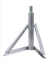
Metal tripod structure with a cylindrical top and three triangular legs, labeled Fig. 1: ZSO 181 (no text on the structure itself)Fig. 1: ZSO 181
There are two main ways in which the support frame can be secured. These require on the one hand the installation of IPB 200 beams (see Fig. 2) and on the other hand the laying of a flat concrete slab (see Fig. 3).
Slab, IPB 200 and clamping plates

Fig. 2: Installation on a slab with IPB 200, using clamping plates
Slab and anchor bolts with anchor rod (M24)
When setting up the ZSO 181 support frame on concrete using anchor bolts and an anchor rod ^1) , we recommend you use the support frame as a template to drill the necessary eight anchor holes. The theoretical dimensions are shown in Fig. 3.

1) anchor bolts Upat UKA 3 - M24: Please comply with the current "General building approval conditions"
Fig. 3: Installation on a slab with anchor bolts and an anchor rod
Minimum slab dimensions for various maximum wind speeds


The fastening points near the edge should be spaced equally at a distance a_r .
Fig. 4: Slabs with rectangular and circular layouts
Recommended minimum dimensions of slabs
| V_max in km/h | anchor bolts/anchor rod 2) | Clamping plates on IPB 200 | |
| W x H in m ∅ in m W x H in m | |||
| 200 1.60 x 1.60 | 1.80 1.30 x 1.30 | ||
| 180 1.50 x 1.50 | 1.80 1.30 x 1.30 | ||
| 160 1.50 x 1.50 | 1.70 1.30 x 1.30 | ||
2) The distances from the edge must be in accordance with the "General building approval conditions" for concrete of quality B25
Leading dimensions - forces exerted at the attachment points - weight

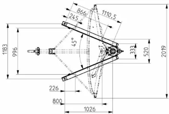
Flow resistance of CAS 180:
Wind surface area: 2.83 m
Drag coefficient c_w to flow inclination: 1,4
Forces at the fastening points:
| Wind speed 200 km/h 180 km/h | 160 km/h | ||||||||||||
| Dynamic pressure | 1.90kN/m^2 | 1.60 kN/m^2 | 1.25kN/m^2 | ||||||||||
| Windload of the antenna | 7.53 kN 6.34 kN | 4.95 kN | |||||||||||
| Torsional moment of the antenna to flow indication | 1.62 kNm | 1.36 kNm | 1.07 kNm | ||||||||||
| Position | 1 | 2 | 3 | 4 | 1 | 2 | 3 | 4 | 1 | 2 | 3 | 4 | |
| Load type* | Tension in kN | 10.4 | 2.3 | 5.7 | 9.5 | 8.8 | 1.9 | 4.8 | 8.0 | 6.9 | 1.5 | 3.8 | 6.3 |
| Tension in kN (Resulting from tensile and transverse load) | 13.1 | 8.8 | 7.6 | 12.1 | 11.1 | 7.4 | 6.4 | 10.2 | 8.6 | 5.8 | 5.0 | 8.0 | |
| Compression in kN | 16.2 | 2.4 | 6.7 | 10.0 | 13.7 | 2.0 | 5.7 | 8.4 | 10.7 | 1.6 | 4.4 | 6.6 | |
| Compression in kN (Resulting from tensile and transverse load) | 18.8 | 8.2 | 7.3 | 12.9 | 15.9 | 6.9 | 6.2 | 10.9 | 12.4 | 5.4 | 4.8 | 8.5 | |
| Transverse load in kN | 9.6 | 8.8 | 6.3 | 8.1 | 8.1 | 7.4 | 5.3 | 6.8 | 6.3 | 5.8 | 4.2 | 5.3 | |
* the load data of the different load types result from partly different, the respective critical load cases.
Weight:
Support frame: approx. 137 kg
CAS 180: approx. 60 kg



- About these instructions
- Intended use
- Securing the support frame
- Slab, IPB 200 and clamping plates
- Slab and anchor bolts with anchor rod (M24)
- Minimum slab dimensions for various maximum wind speeds
- Recommended minimum dimensions of slabs
- Leading dimensions - forces exerted at the attachment points - weight
Marque : KATHREIN
Modèle : ZSO 181
Catégorie : Antenne satellite