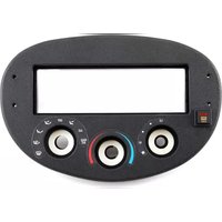
99-5720 - Autoradio Metra - Notice d'utilisation et mode d'emploi gratuit
Retrouvez gratuitement la notice de l'appareil 99-5720 Metra au format PDF.


| Type de produit | Kit d'installation pour autoradio |
| Marque | Metra |
| Modèle | 99-5720 |
| Dimensions (H x L x P) | 10 cm x 18 cm x 10 cm |
| Poids | 0,5 kg |
| Matériau | Plastique ABS |
| Couleur | Noir |
| Compatibilité véhicule | Toyota Camry, Corolla, RAV4 (sélectionnés) |
| Type de façade | Double DIN |
| Fonctions principales | Fixation de l'autoradio, intégration esthétique |
| Contenu de l'emballage | Kit de montage, vis, instructions |
| Entretien et nettoyage | Essuyer avec un chiffon doux et sec |
| Sécurité | Installation par un professionnel recommandée |
| Pièces détachées et réparabilité | Pièces non réparables individuellement, remplacer l'ensemble |
| Informations générales | Kit de remplacement pour autoradio d'origine |
FOIRE AUX QUESTIONS - 99-5720 Metra
Questions des utilisateurs sur 99-5720 Metra
0 question sur cet appareil. Repondez a celles que vous connaissez ou posez la votre.
Poser une nouvelle question sur cet appareil
Téléchargez la notice de votre Autoradio au format PDF gratuitement ! Retrouvez votre notice 99-5720 - Metra et reprennez votre appareil électronique en main. Sur cette page sont publiés tous les documents nécessaires à l'utilisation de votre appareil 99-5720 de la marque Metra.
MODE D'EMPLOI 99-5720 Metra

INSTALLATION INSTRUCTIONS FOR PART 99-5720
APPLICATIONS
Ford Escort/Escort ZX2 1997-2002/ ZX2 2001-2003, Mercury Tracer 1997-1999 99-5720
KIT FEATURES
• DIN radio provision
• Incorporates factory climate controls into installation

KIT COMPONENTS
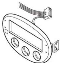
• A) Integrated mounting kit and power harness • B) Speaker harness
A
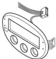
B
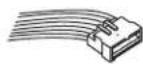
WIRING & ANTENNA CONNECTIONS (sold separately)
Wiring Harness:
• 70-5720 - 2003 models
• 70-5603 - 1997-2003 all models with amp
• 1997-2002 models included with kit
Antenna Adapter:
- Not required
TOOLS REQUIRED
• 86-5618 radio removal keys
- Torx head screwdriver • Cutting tool
CAUTION: Metra recommends disconnecting the negative battery terminal before beginning any installation. All accessories, switches, and especially air bag indicator lights must be plugged in before reconnecting the battery or cycling the ignition.
NOTE: Refer to the instructions included with the aftermarket radio.

99-5720
Table of Contents
Dash Disassembly
Ford Escort 1997-2002
- Ford Escort ZX2 1997-2002
- Ford ZX2 2001-2003
- Mercury Tracer 1997-1999
Kit Assembly
- DIN radio provision ....6
Harness Wiring
- Connections to be made ....6
All Vehicles
- Reach under the driver's side dash and unclip the temperature control cable.
- Using Metra's 86-5618, pull the factory radio/climate control panel from the dash. (Figure A)
- Disconnect the switch power harness, antenna plug, radio/speaker power harnesses and vacuum hose harness.
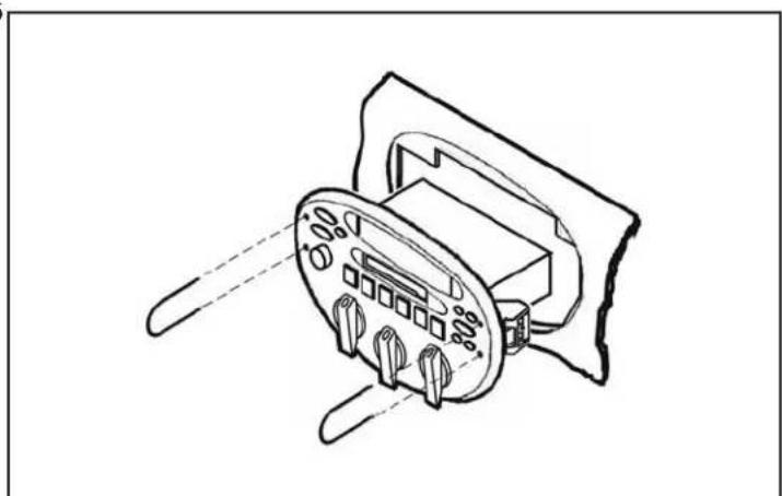
(Figure A)
Dash Disassembly 99-5720
All Vehicle
-
Turn the integrated control panel over and disconnect the vent control harness ("A"), fan speed control harness ("B"), and defroster harness ("C"). (Figure B)
-
Unclip the main switch harness from the side of the factory radio (this harness connects the fan speed control harness, vent control harness and defroster harness).
Continued on next page

(Figure B)
(Figure C)

Dash Disassembly 99-5720
All Vehicles
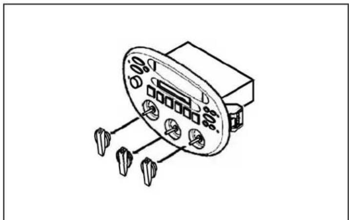
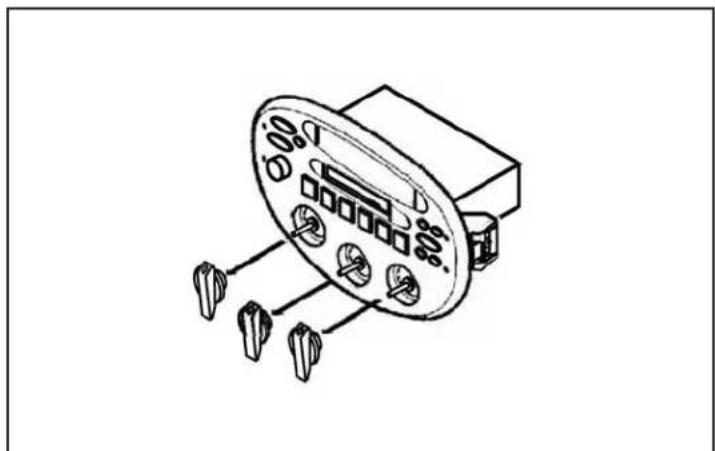
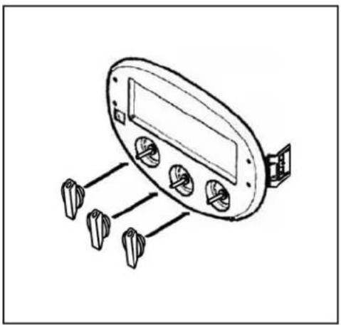
- Turn the factory climate control dials into a vertical position and pull the dials off. (Figure C)
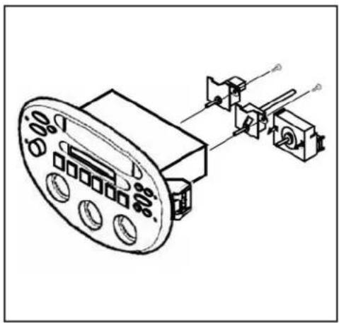
- Unclip the vent control switch and remove. Remove (2) Torx head screws securing the temperature control switch and fan speed control switch and remove. (Figure D)


(Figure E)(Figure D) (Figure F)
- Mount the switches to the back of the Integrated Mounting Kit with the same Torx head screws. (Figure E)
- Holding the climate control dials in a vertical position insert the dials onto the posts of the mounted switches and secure. (Figure F)
| 4 |

Dash Disassembly 99-5720
All Vehicles
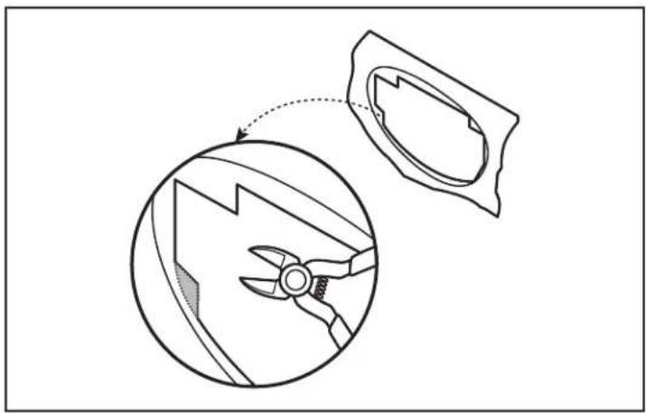
- Cut and remove the shaded portions of the sub-dash lip. (Figure G)
CAUTION: Note, the assembly will not snap into the sub-dash if this step is not done.
-
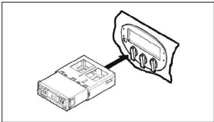
Make all wiring connections to the integrated mounting kit and snap the assembly into the sub-dash. (Figure H)
-
Reach under the driver's side dash and re-attach the temperature control cable.
Continue to kit assembly

(Figure H)(Figure G)
DIN radio provision
- Locate the factory wiring harness in the dash. Metra recommends using the proper mating adapter from Metra or AXXESS. Reconnect the negative battery terminal and test the radio for proper operation.
- Slide the DIN cage into the integrated mounting kit and secure by bending the metal locking tabs down.
- Slide the aftermarket radio into the cage until secure. (Figure A)
(Figure A)
Connections to be made
- Connect the Yellow wire to the 12-volt constant wire.
- Connect the Red wire to the ignition/accessory wire.
- Connect the Orange wire to the illumination wire (If the aftermarket radio has no illumination wire, cap off the Orange wire).
- Connect the Black wire to the ground wire.
- Connect the Blue wire to the antenna turn on wire.
- Connect the White wire to the left front positive speaker output.
- Connect the White/Black wire to the left front negative speaker output.
- Connect the Gray wire to the right front positive speaker output.
- Connect the Gray/Black wire to the right front negative speaker output.
- Connect the Green wire to the radio's left rear positive speaker output.
- Connect the Green/Black wire to the radio's left rear negative speaker output.
- Connect the Purple wire to the radio's right rear positive speaker output.
- Connect the Purple/Black wire to the radio's right rear negative speaker output.
Metra
99-5720
Notes

INSTALLATION INSTRUCTIONS FOR PART 99-5720


KNOWLEDGE IS POWER
Enhance your installation and fabrication skills by parrolling in the most recognized and suggested
mobile electronics school in our industry.
Log onto www.installerinstitute.com or call
600-354-6782 for more information and take steps toward a better tomorrow.

Metra recommends MECP
certified technicians

INSTRUCCIONES DE INSTALACIÓN PARA LA PIEZA 99-5720
APLICACIONES
Ford Escort/Escort ZX2 1997-2002/ ZX2 2001-2003, Mercury Tracer 1997-1999 99-5720
CARACTERÍSTICAS DEL KIT
• Provisión de radio DIN
- Incorpora los controles de clima de fábrica a la instalación

COMPONENTES DEL KIT
- A) Kit de montaje integrado y arnés de energía • B) Arnés de bocinas
A
B

CABLEADO Y CONEXIONES DE ANTENA
Arnés de cableado: (se venden por separado)
• 1997-2002 modelos: Incluido con el kit
• Los modelos de 2003: 70-5720
Adaptador de antena:
- No se requiere
HERRAMIENTAS REQUERIDAS
- Llaves de remoción Metra 86-5618
• Destornillador Torx • Cortador
PRECAUCIÓN: Metra recomienda desconectar el terminal negativo de la batería antes de comenzar cualquier instalación. Todos los accesorios, interruptores y, especialmente, las luces indicadoras de airbag deben estar enchufados antes de volver a conectar la batería o comenzar el ciclo de ignición.
NOTA: Remítase a las instrucciones incluidas con el radio de postventa.
99-5720
Indice
Desmontaje del tablero
Ford Escort 1997-2002 2-5
- Ford Escort ZX2 1997-2002 2-5
- Ford ZX2 2001-2003 2-5
- Mercury Tracer 1997-1999 2-5
Ensamble del kit
- Provisión de radio DIN ....6
Arnés de cableado
- Conexiones que se deben hacer ....6
Todos los vehículos
- Meta la mano debajo del tablero del lado del conductor y desenganche el cable de control de temperatura.
- Usando 86-5618 de Metra, saque el panel de control de radio/clima de fábrica del tablero. (Figura A)
- Desconecte el arnés de energía para interruptores, el conector de la antena, los arneses de energía para el radio/las bocinas y el arnés de la manguera de vacío.

(Figura A)

Desmontaje del tablero 99-5720
Todos los vehículos
- Voltee el panel de control integrado y desconecte el arnés de control de rejillas ("A"), el arnés de control de velocidad del ventilador ("B") y el arnés del desempañador ("C"). (Figura B)
- Desenganche el arnés del interruptor principal del costado de la unidad de
fábrica (este arnés se conecta al arnés de control de velocidad del ventilador, al arnés de control de las rejillas y al arnés del desempañador).
Continúa en la página

(Figura B)
(Figura C)
Desmontaje del tablero 99-5720
Todos los vehículos
- Ponga los selectores de control de clima de fábrica en posición vertical y jálelos para quitarlos. (Figura C)
- Desenganche el interruptor de control de rejillas y retire. Retire los (2) tornillos de cabeza Torx que sostienen el interruptor del control de temperatura y el interruptor del control de velocidad de ventilador y retire. (Figura D)

(Figura E)(Figura D) (Figura F)
- Monte los interruptores en la parte posterior del kit de montaje integrado con los mismos tornillos de cabeza Torx. (Figura E)
- Sosteniendo los selectores del control de clima en posición vertical, insértelos en los postes de los interruptores montados y asegúrelos. (Figura F)

Desmontaje del tablero 99-5720
Todos los vehículos
- Corte y retire las porciones sombreadas del reborde del sub tablero. (Figura G) PRECAUCIÓN: Nota, la asamblea no encajará en el sub-guión si este paso no se hace.
- Haga todas las conexiones de cableado al kit de montaje integrado y coloque a presión el ensamble en el sub tablero. (Figura H)

- Meta la mano debajo del tablero del lado del conductor y vuelva a conectar el cable de control de temperatura. Continuará al ensamble del kit

(Figura H)(Figura G)
Provisión de radio DIN
- Ubique el arnés del cableado de fábrica en el tablero. Metra recomienda usar el adaptador de acoplamiento adecuado de Metra o AXXESS. Vuelva a conectar el terminal negativo de la batería y pruebe la unidad para verificar que funcione correctamente.
- Deslice la reja DIN en el kit integrado de montaje y sujétela doblando hacia abajo las pestañas de metal.
- Deslice la unidad central de mercado secundario en la reja hasta que quede firme. (Figura A)

(Figura A)
Conexiones que se deben hacer
- Conecte el cable Amarillo con el cable constante/de memoria del radio.
- Conecte el cable Rojo con el cable de accesorios del radio.
- Conecte el cable Anaranjado/Blanco al cable de iluminación del radio de mercado secundario. Si el radio de mercado secundario no tiene cable de iluminación, cubra con cinta el cable Anaranjado/Blanco.
- Conecte el cable Negro con el cable de tierra del radio.
- Conecte el cable Azul con el encendido de la antena del radio.
- Conecte el cable Blanco con el cable de la bocina izquierda frontal (+) del radio.
- Conecte el cable Blanco/Negro con el cable de la bocina izquierda frontal (-) del radio.
- Conecte el cable Gris con el cable de la bocina derecha frontal (+) del radio.
- Conecte el cable Gris/Negro con el cable de la bocina derecha frontal (-) del radio.
- Conecte el cable Verde con el cable de la bocina izquierda de atrás (+) del radio.
- Conecte el cable Verde/Negro con el cable de la bocina izquierda de atrás (-) del radio.
- Conecte el cable Púrpura con el cable de la bocina derecha de atrás (+) del radio.
- Conecte el cable Púrpura/Negro con el cable de la bocina derecha de atrás (-) del radio.
Metra
99-5720
Notas

INSTRUCCIONES DE INSTALACIÓN PARA LA PIEZA 99-5720


EL CONOCIMIENTO ES PODER
Mejore sus habilidades de instalación y fabricación inscribiéndose en la escuela de dispositivos electrónicos móviles más reconocida y respetada de nuestra industria. Registrese en www.installerinstitute.com o llame al 800-354-6782 para obtener más información y avance hacia un futuro mejor.

Metra recomienda técnicos con certificación del Programa de Certificación en Electrónica Móvil (Mobile Electronics Certification Program, MECP).
- FORD ESCORT/ESCORT ZX2 1997-2002/ ZX2 2001-2003, MERCURY TRACER 1997-1999 99-5720
- KIT FEATURES
- KIT COMPONENTS
- WIRING & ANTENNA CONNECTIONS (SOLD SEPARATELY)
- TOOLS REQUIRED
- TABLE OF CONTENTS
- DASH DISASSEMBLY
- KIT ASSEMBLY
- HARNESS WIRING
- ALL VEHICLES
- ALL VEHICLE
- DIN RADIO PROVISION
- CONNECTIONS TO BE MADE
- CARACTERÍSTICAS DEL KIT
- COMPONENTES DEL KIT
- CABLEADO Y CONEXIONES DE ANTENA
- HERRAMIENTAS REQUERIDAS
- INDICE
- DESMONTAJE DEL TABLERO
- ENSAMBLE DEL KIT
- ARNÉS DE CABLEADO
- TODOS LOS VEHÍCULOS
- DESMONTAJE DEL TABLERO 99-5720
- PROVISIÓN DE RADIO DIN
- CONEXIONES QUE SE DEBEN HACER
Marque : Metra
Modèle : 99-5720
Catégorie : Autoradio