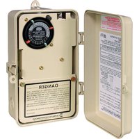
RC2343PT - Télécommande INTERMATIC - Notice d'utilisation et mode d'emploi gratuit
Retrouvez gratuitement la notice de l'appareil RC2343PT INTERMATIC au format PDF.


| Type de produit | Télécommande |
| Marque | Intermatic |
| Modèle | RC2343PT |
| Dimensions (L x l x H) | 10 x 5 x 2 cm |
| Poids | 50 g (avec piles) |
| Alimentation | 2 piles AAA (non fournies) |
| Type de piles | Alcalines recommandées |
| Portée maximale | 30 m en champ libre |
| Fréquence de fonctionnement | 433 MHz |
| Fonctions principales | Contrôle à distance de prises ou appareils Intermatic compatibles |
| Nombre de canaux | 1 (modulation simple) |
| Indicateur lumineux | LED de transmission |
| Matériau du boîtier | Plastique ABS |
| Couleur | Blanc |
| Température d'utilisation | 0 °C à 40 °C |
| Entretien et nettoyage | Essuyer avec un chiffon doux et sec. Ne pas utiliser de produits chimiques. |
| Sécurité | Ne pas exposer à l'eau ou à l'humidité excessive. Tenir hors de portée des enfants. |
| Pièces détachées | Aucune pièce détachable disponible. Piles non fournies. |
| Réparabilité | Non réparable par l'utilisateur. En cas de dysfonctionnement, remplacer l'appareil. |
| Informations générales | Conçu pour une utilisation domestique. Compatible avec les récepteurs Intermatic série PT. |
FOIRE AUX QUESTIONS - RC2343PT INTERMATIC
Questions des utilisateurs sur RC2343PT INTERMATIC
0 question sur cet appareil. Repondez a celles que vous connaissez ou posez la votre.
Poser une nouvelle question sur cet appareil
Téléchargez la notice de votre Télécommande au format PDF gratuitement ! Retrouvez votre notice RC2343PT - INTERMATIC et reprennez votre appareil électronique en main. Sur cette page sont publiés tous les documents nécessaires à l'utilisation de votre appareil RC2343PT de la marque INTERMATIC.
MODE D'EMPLOI RC2343PT INTERMATIC
WIRING DIAGRAMS RC2343PT
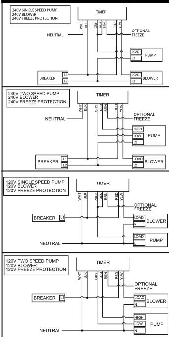

flowchart
graph TD
    A["240V SINGLE SPEED PUMP\n240V BLOWER\n240V FREEZ PROTECTION"] --> B["TIMER"]
    B --> C["NEUTRAL"]
    C --> D["BREAKER L1\nB"]
    B --> E["OPTIONAL\nFREEZE"]
    E --> F["LOAD L2\nPUMP"]
    B --> G["BLOWER"]
    G --> H["LOAD L2\nBLOWER"]
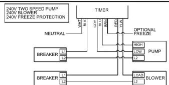
flowchart
graph TD
    A["240V TWO SPEED PUMP"] --> B["240V BLOWER"]
    B --> C["240V FREEZE PROTECTION"]
    D["NEUTRAL"] --> E["BREAKER L1"]
    F["TIMER"] --> G["PRY"]
    F --> H["BUX"]
    F --> I["RHO"]
    F --> J["RRW"]
    K["OPTIONAL FREEZE"] --> L["RIGHT"]
    K --> M["Low"]
    K --> N["PUMP"]
    O["BREAKER L2"] --> P["LOAD"]
    O --> Q["L2"]
    R["BREAKER L3"] --> S["BLOWER"]
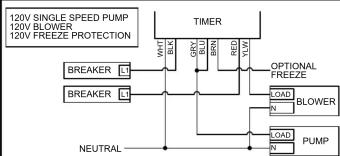
flowchart
graph TD
    A["120V SINGLE SPEED PUMP"] --> B["TIMER"]
    C["120V BLOWER"] --> B
    D["120V FREEZ PROTECTION"] --> B
    B --> E["WEAT"]
    B --> F["BCLK"]
    B --> G["GRY"]
    B --> H["BRDN"]
    B --> I["RED"]
    B --> J["120V"]
    E --> K["NEUTRAL"]
    F --> L["OPTIONAL FREEZE"]
    G --> M["BLOWER"]
    H --> N["PUMP"]
    I --> O["LOAD"]
    I --> P["N"]
    J --> Q["LOAD"]
    J --> R["N"]

flowchart
graph TD
    A["120V TWO SPEED PUMP"] --> B["BREAKER L"]
    C["120V BLOWER"] --> D["BREAKER L"]
    B --> E["TIMER"]
    D --> E
    E --> F["TW"]
    E --> G["OPTIONAL FREEZE"]
    G --> H["LOAD"]
    G --> I["BLOWER"]
    H --> J["N"]
    I --> K["N"]
    J --> L["HIGH"]
    K --> M["LOW"]
    L --> N["PUMP"]
    M --> O["N"]
    N --> P["PUMP"]
    Q["NEUTRAL"] --> R["Breaker L"]
    S["Breaker L"] --> T["Breaker L"]
IMPORTANT NEUTRAL WIRE MUST ALWAYS BE USED
NOTES:
-
Dot (●) indicates twist on wire connector
-
If freeze protection is not required, permanently cap (twist on wire connector) brown lead.
LIMITED WARRANTY
Warranty service is available by either (a) returning the product to the dealer from whom the unit was purchased or (b) completing a warranty claim online at www.intermatic.com. This warranty is made by: Intermatic Incorporated, Customer Service 1950 Innovation Way, Suite 300, Libertyville, IL 60048.
For warranty service go to: http://www.Intermatic.com or call 815-675-7000
Because of our commitment to continuing research and improvements, Intermatic Incorporated reserves the right to make changes, without notice, in the specifications and material contained herein and shall not be responsible for any damages, direct or consequential, caused by reliance on the material presented.
INTERMATIC INCORPORATED, LIBERTYVILLE, IL 60048
158--02178

NTERMATIC®
RC2000 SERIES
AIR ACTUATED SPA CONTROLS
INSTALLATION
OPERATION &
SERVICE MANUAL
FOUR FUNCTION AIR SWITCH WITH TIMER
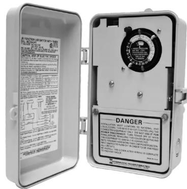
Model: RC2343PT - Plastic Outdoor Enclosure Suitable for POOL/SPA Equipment Control
RATINGS: 20 A (R), 1 HP, 120 V, 60 Hz.; 20 A (R), 2 HP, 240 V, 60 Hz.
READ AND FOLLOW ALL INSTRUCTIONS • IMPORTANT SAFTEY INSTRUCTIONS • SAVE THESE INSTRUCTIONS
! WARNING Risk of Fire or Electric Shock
- Electrical connections to this equipment must be accomplished by a qualified electrician in accordance with the National Electrical Code and in accordance with all local codes.
- Disconnect power at the circuit breaker(s) or disconnect switch(es) before installing or servicing. More than one circuit breaker or disconnect switch may be required to de-energize the equipment before servicing.
- For outdoor locations or wet locations (rain-tight), conduit hubs that comply with requirements of the UL514B (standard for fitting conduit and outlet boxes) are to be used.
- Do NOT exceed maximum current carrying capacity.
- Reinstall wire terminal cover after wiring is complete.
- KEEP DOOR CLOSED AT ALL TIMES when not servicing.
- The control panel is to be a minimum of 3 M. (in Canada) or 5 ft. (in USA) from the inside wall of the pool, spa, or pond, unless separated from the body of water by a fence, wall or other permanent barrier that will make the unit inaccessible to persons in the water.
- For grounding and bonding of this Control and the installation, refer to section 680 of the National Electrical Code.
GENERAL INFORMATION
This Air Switch is designed to control two separate pieces of equipment with one air button. Without electricity at the spa side, it can safely control a pump and blower. Each press of the air button will cycle between the sequences shown below. When left in sequence one, the timer will operate the pump at the times set for daily filtration. It also has an input for freeze protection.
| EQUIPMENT | SEQUENCE | ||||
| 1 | 2 | 3 | 4 | ||
| PUMP (SINGLE-SPEED) | TIMERON/OFF | ON | ON | OFF | |
| PUMP (TWO-SPEED) | TIMERON/OFFLOW | HIGH | HIGH | OFF | |
| BLOWER OFF OFF | ON | ON | |||
1
INSTALLATION - MODEL RC2343PT
- Select the appropriate wiring diagram on Page 4 and prepare your installation layout. Make sure only copper (solid or stranded) conductors are used, properly sized and suitable for the installation. Each equipment must have its own power disconnect and must be grounded properly.
IMPORTANT: NEUTRAL MUST ALWAYS BE CONNECTED TO THE WHITE LEAD OF THE CONTROL.
-
Hang Air Switch on a flat vertical surface or other support, using hardware suitable for the purpose. Make sure the air button is within the range of the Air Switch. NOTE: The optimum range of this Air Switch is 100 feet. However, factors beyond control of the manufacturer (like the size of the air pump, the I.D. of the air hose, etc.) will determine the actual distance between the mechanism and the air pump.
-
Prepare the necessary conduit runs, including one for the air hose, terminate them at both ends and pull-in the conductors as specified by the installation layout.
- Follow proper wiring diagram, make LINE, PUMP, BLOWER and FREEZE PROTECTION (if applicable) connections as shown. Make sure the installation is securely grounded.
- Make air hose connections. Remove compression nut from Pulse Switch, feed air hose through hole, connect hose to Pulse Switch and re-install compression nut. Repeat procedure at Air Button end of hose. Make sure connections are tight.
- Check wiring, tightness of connections and grounding. Close wiring compartment and test installation.
- Set timer, see instructions below.
TROUBLESHOOTING
SYMPTOM CAUSE(S) CORRECTIVE ACTION
| 1. Pump will not operate or operates on low speed only. 1b. Defective air button Replace air button - see note 1. | ||
| 1c. Water in air hose Blow-out air hose - see note 2. | ||
| 1d. Defective pulse switch Replace pulse switch - see note 2. | ||
| 1e. Defective relay Replace relay - see note 3. | ||
| 1f. Air button is too far Install larger air button. | ||
| 2. Pump will not turn off or operates on high speed only. 2a. Air hose disconnected Check hose connections. | ||
| 2b. Defective air button Replace air button - see note 1. | ||
| Replace relay - see note 3. | ||
| 3. Pump turns on/off by itself. 3a. Defective pulse switch Replace pulse switch. | ||
| 3b. Water in air hose Blow-out air hose - see note 2. | ||
| 3c. Changing air pressure in air hose Reroute air hose. |
OPERATION

- Insert ON (green) and OFF (red) trippers into dial at desired ON and OFF times (Fig. 1). Be sure trippers are firmly pressed against dial surface and at least one space is left between ON and OFF trippers (Fig. 2).
- Turn dial clockwise one or more revolutions until correct time of day is next to arrow in center of dial (Fig. 3).


- The knob in the upper left corner of timer is for operating the Filter pump manually when needed. By turning it COUNTERCLOCKWISE, it will start or stop the filtering/heating cycle ahead of the scheduled start/stop time. Automatic operation will resume with the next scheduled cycle.
-
Timer comes with two sets of trippers, allowing the choice of two cycles per day. If only one cycle is needed, the extra trippers may be stored on the dial by placing SAME color trippers next to each other.
-
To suspend automatic operation, remove red and green trippers from Dial and Store them in a convenient place.
- Additional trippers can be obtained by contacting an Intermatic distributor or Intermatic Customer Service at (815-675-7000 and asking for 156PB10398A tripper kit (2 ON and 2 OFF trippers).
TROUBLESHOOTING NOTES
A Pneumatic Remote Control (Air Switch) consists of an air button (air pump, transmitter), a pulse switch (air Sensor, receiver) and a relay (either alternate action or stepper). The air button is connected to the pulse switch by the air hose. By pressing on the air button at one end of the air hose, the increased pressure will momentarily close the contacts of the pulse switch at the other end of the air hose, thus energizing the coil of the relay. The relay turns ON or OFF the connected equipment.
- An air button with ruptured seal or bellows inside, will not produce sufficient air pressure to operate the momentary air switch and could lead to total break down.
- Water in air hose will damage the pulse switch and it is caused by a faulty air button (see note 1 above) or condensation. In either case, it must be drained and the cause found and corrected. To reduce condensation,
- A defective relay is either due to contact or coil failure. Contact failure is caused by over-load or cross wiring and coil failure is caused by 240 volt connected across the 120 V coil or permanently applied 120 V. (The relay is designed for intermittent duty only). Permanently applied 120 V could be the result of water in the air hose (see note 2 above) or a spa cover placed over (and depressing) the air button. In any case, the cause must be found, corrected and the relay replaced.
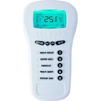


Marque : INTERMATIC
Modèle : RC2343PT
Catégorie : Télécommande