AD80 - Électronique marine SIMRAD - Notice d'utilisation et mode d'emploi gratuit
Retrouvez gratuitement la notice de l'appareil AD80 SIMRAD au format PDF.


| Type de produit | Vérin linéaire pour pilote automatique marin |
| Marque | Simrad |
| Modèle | AD80 |
| Usage | Direction assistée pour bateaux, compatible avec systèmes Simrad |
| Longueur | 610 mm |
| Diamètre | 90 mm |
| Poids | 6,5 kg |
| Alimentation | 12 V ou 24 V CC (selon version) |
| Consommation maximale | 5 A à 12 V, 2,5 A à 24 V |
| Force de poussée | 1500 N |
| Course | 200 mm (ajustable) |
| Vitesse de déplacement | 25 mm/s |
| Indice de protection | IP66 |
| Matériaux | Acier inoxydable et aluminium |
| Température de fonctionnement | -10 °C à +50 °C |
| Fonctions principales | Commande de barre, maintien du cap, intégration au réseau Simrad |
| Entretien | Lubrification annuelle des joints, inspection des câbles |
| Nettoyage | Eau douce et chiffon non abrasif ; éviter les produits agressifs |
| Sécurité | Ne pas dépasser la charge nominale ; couper l'alimentation avant maintenance |
| Pièces détachées | Joint de tige, câble, fusible ; disponibles chez revendeurs agréés |
| Réparabilité | Réparation possible par technicien qualifié ; pas de pièces consommables |
FOIRE AUX QUESTIONS - AD80 SIMRAD
Questions des utilisateurs sur AD80 SIMRAD
0 question sur cet appareil. Repondez a celles que vous connaissez ou posez la votre.
Poser une nouvelle question sur cet appareil
Téléchargez la notice de votre Électronique marine au format PDF gratuitement ! Retrouvez votre notice AD80 - SIMRAD et reprennez votre appareil électronique en main. Sur cette page sont publiés tous les documents nécessaires à l'utilisation de votre appareil AD80 de la marque SIMRAD.
MODE D'EMPLOI AD80 SIMRAD

SIMRAD
AD80
THRUSTER INTERFACE,
INSTALLATION GUIDE

natural_image
Isometric line drawing of a rectangular electronic device with a side panel and mounting bracket (no text or symbols)Parts included Dimensions
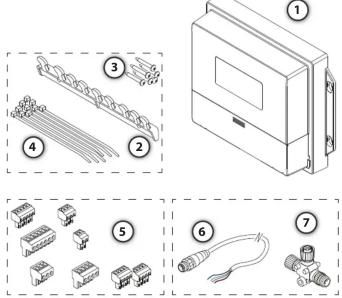
1 1 * AD80 Computer
2 1 * Cable retainer
3 6 * Fixing screws, 3.5 * 19 mm (DIN7981B)
4 10* Strips
5 8* Connectors
6 1 * Micro-C Drop cable (male)
7 1 * Micro-C T-Joiner
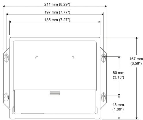


The image is too blurry to recognize any text content.
For technical specifications,
certificates and declarations,
refer to the product web site on:

pro.simrad-yachting.com

www.simrad-yachting.com

Mounting

natural_image
Technical line drawing of a mechanical assembly with labeled components and a magnified inset showing detail (no text or symbols present)System wiring

flowchart
graph TD
    A["12V DC"] --> B["AC70 S8"]
    B --> C["1* NMEA 0183 IN/OUT"]
    C --> D["AP60"]
    D --> E["AP70/80"]
    E --> F["12/24 V DC"]
    F --> G["GPS SENSOR"]
    G --> H["COMPASS"]
    H --> I["12/24 V DC"]
    I --> J["OPTION"]
    J --> K["NMEA 0183 IN/OUT"]
    K --> L["AD80/SD80"]
    L --> M["DRIVE UNIT"]
    M --> N["THRUSTER CONTROL"]
    N --> O["Micro-C Drop cable, male"]
    N --> P["Micro-C T-Joiners"]
    N --> Q["Micro-C Drop cable, female"]
    N --> R["SimNet to Micro-C (male) Drop cable"]
    N --> S["Micro-C Power cable with 120 Ohm terminator, female"]


flowchart
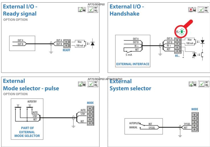
Electrical wiring diagram for external I/O and external mode selector, showing signal paths, handshakes, and terminal connections.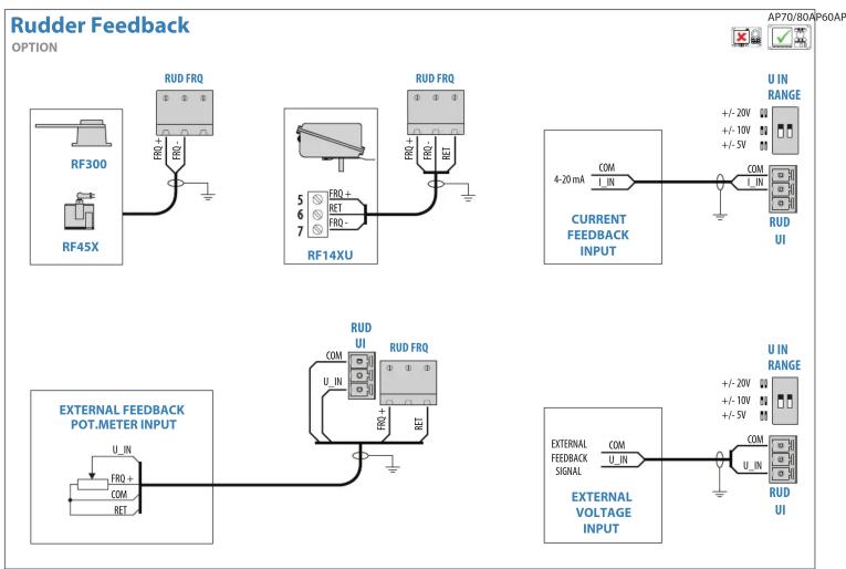
flowchart
graph TD
    A["RF300"] --> B["RUD FRQ"]
    C["RF45X"] --> D["RUD FRQ"]
    E["RF14XU"] --> F["RUD FRQ"]
    G["4-20 mA"] --> H["COM I_IN"]
    H --> I["CURRENT FEEDBACK INPUT"]
    I --> J["U IN RANGE"]
    K["External Feedback POT.METER INPUT"] --> L["RUD UI"]
    L --> M["COM U_IN"]
    M --> N["RUD FRQ"]
    O["External Feedback Signal"] --> P["COM U_IN"]
    P --> Q["U IN RANGE"]
    Q --> R["RUD UI"]
Marque : SIMRAD
Modèle : AD80
Catégorie : Électronique marine