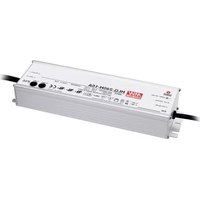
HLG-240H-24B - Batterie VELLEMAN - Notice d'utilisation et mode d'emploi gratuit
Retrouvez gratuitement la notice de l'appareil HLG-240H-24B VELLEMAN au format PDF.


| Type de produit | Batterie rechargeable au lithium |
| Marque | Velleman |
| Modèle | HLG-240H-24B |
| Dimensions (L x l x h) | 200 x 125 x 65 mm |
| Poids | 2,5 kg |
| Tension nominale | 24 V DC |
| Capacité | 10 Ah |
| Type de connexion | Bornes à vis |
| Alimentation d'entrée | 100-240 V AC, 50/60 Hz |
| Protection intégrée | Protection contre les surcharges et décharges profondes |
| Température de fonctionnement | -20°C à +60°C |
| Humidité relative | 20% à 80% sans condensation |
| Matériau du boîtier | ABS ignifuge |
| Entretien et nettoyage | Nettoyer avec un chiffon sec et doux. Ne pas utiliser de liquides. |
| Sécurité | Ne pas court-circuiter, ne pas exposer à la chaleur ou à l'eau |
| Pièces détachées disponibles | Câbles de connexion, bornes de remplacement |
| Réparabilité | Réparable par un technicien qualifié |
| Garantie | 2 ans |
FOIRE AUX QUESTIONS - HLG-240H-24B VELLEMAN
Questions des utilisateurs sur HLG-240H-24B VELLEMAN
0 question sur cet appareil. Repondez a celles que vous connaissez ou posez la votre.
Poser une nouvelle question sur cet appareil
Téléchargez la notice de votre Batterie au format PDF gratuitement ! Retrouvez votre notice HLG-240H-24B - VELLEMAN et reprennez votre appareil électronique en main. Sur cette page sont publiés tous les documents nécessaires à l'utilisation de votre appareil HLG-240H-24B de la marque VELLEMAN.
MODE D'EMPLOI HLG-240H-24B VELLEMAN

■ Features :
• Universal AC input / Full range (up to 305VAC)
• Built-in active PFC function
* Protections: Short circuit / Over current / Over voltage / Over temperature
• Cooling by free air convection
• OCP point adjustable through output cable or internal potentiometer
• IP67 / IP65 design for indoor or outdoor installations
• Three in one dimming function (1\~10Vdc or PWM signal or resistance)
• Suitable for LED lighting and street lighting applications
• Compliance to worldwide safety regulations for lighting
• Suitable for dry / damp / wet locations
- Type "HL" for use in class 1, Division 2 hazardous(Classified) location luminaires
• 7 years warranty (Note.10)

TAIWAN EXCEPTIONS 2011


SELV
IP65
IP67



HLG-240H-12 A
Blank : IP67 rated. Cable for I/O connection.
A: IP65 rated. Output voltage and constant current level can be adjusted through internal potentiometer.
B: IP67 rated. Constant current level adjustable through output cable with 1\~10Vdc or 10V PWM signal or resistance.
C : Terminal block for I/O connection. Output voltage and constant current level can be adjusted through internal potentiometer.
D (option, safety pending) : IP67 rated. Timer dimming function, contact MEAN WELL for details.
SPECIFICATION
| MODEL | HLG-240H-12 | HLG-240H-15 | HLG-240H-20 | HLG-240H-24 | HLG-240H-30 | HLG-240H-36 | HLG-240H-42 | HLG-240H-48 | HLG-240H-54 | |
| OUTPUT | DC VOLTAGE | 12V | 15V | 20V | 24V | 30V | 36V | 42V | 48V | 54V |
| CONSTANT CURRENT REGIONNote.4 | 6~12V | 7.5~15V | 10~20V | 12~24V | 15~30V | 18~36V | 21~42V | 24~48V | 27~54V | |
| RATED CURRENT | 16A | 15A | 12A | 10A | 8A | 6.7A | 5.72A | 5A | 4.45A | |
| RATED POWER | 192W | 225W | 240W | 240W | 240W | 241.2W | 240.24W | 240W | 240.3W | |
| RIPPLE & NOISE (max.) Note.2 | 150mVp-p | 150mVp-p | 150mVp-p | 150mVp-p | 200mVp-p | 250mVp-p | 250mVp-p | 250mVp-p | 350mVp-p | |
| VOLTAGE ADJ. RANGE Note.6 | 11.2~12.8V | 14~16V | 18.6~21.4V | 22.4~25.6V | 28~32V | 33.5~38.5V | 39~45V | 44.8~51.2V | 50~57V | |
| CURRENT ADJ. RANGE | Can be adjusted by internal potentiometer A type and C type only | |||||||||
| 8~16A | 7.5~15A | 6~12A | 5~10A | 4~8A | 3.3~6.7A | 2.86~5.72A | 2.5~5A | 2.23~4.45A | ||
| VOLTAGE TOLERANCE Note.3 | ±2.5% | ±2.0% | ±1.0% | ±1.0% | ±1.0% | ±1.0% | ±1.0% | ±1.0% | ±1.0% | |
| LINE REGULATION | ±0.5% | ±0.5% | ±0.5% | ±0.5% | ±0.5% | ±0.5% | ±0.5% | ±0.5% | ±0.5% | |
| LOAD REGULATION Note.8 | ±2.0% | ±1.5% | ±1.0% | ±0.5% | ±0.5% | ±0.5% | ±0.5% | ±0.5% | ±0.5% | |
| SETUP, RISE TIME Note.9 | 1000ms,80ms/115VAC 500ms,80ms/230VAC at full load | |||||||||
| HOLD UP TIME (Typ.) | 15ms at full load 230VAC /115VAC | |||||||||
| INPUT | VOLTAGE RANGE Note.5 | 90~305VAC 127~431VDC | ||||||||
| FREQUENCY RANGE | 47~63Hz | |||||||||
| POWER FACTOR (Typ.) | PF>0.98/115VAC, PF>0.95/230VAC at full load (Please refer to "Power Factor Characteristic" curve) | |||||||||
| TOTAL HARMONIC DISTORTION | THD<20% when output loading≥50% at 115VAC/230VAC input and output loading≥75% at 277VAC input | |||||||||
| EFFICIENCY (Typ.) | 90% | 90% | 91.5% | 92.5% | 92.5% | 92.5% | 92.5% | 93% | 93.5% | |
| AC CURRENT (Typ.) | 4A/115VAC 2A/230VAC 1.2A/277VAC | |||||||||
| INRUSH CURRENT (Typ.) | COLD START 75A(width=570s measured at 50% peak) at 230VAC | |||||||||
| MAX. No. of PSUs on 16A CIRCUIT BREAKER | 2 units (circuit breaker of type B) / 4 units (circuit breaker of type C) at 230VAC | |||||||||
| LEAKAGE CURRENT | <0.75mA / 277VAC | |||||||||
| PROTECTION | OVER CURRENT Note.4 | 95~108% | ||||||||
| Protection type: Constant current limiting, recovers automatically after fault condition is removed | ||||||||||
| SHORT CIRCUIT | Hiccup mode, recovers automatically after fault condition is removed | |||||||||
| OVER VOLTAGE | 13.5~18V | 17.5~21.5V | 23.5~27.5V | 27~34V | 33~39V | 43~49V | 48~54V | 55~63V | 60~67V | |
| Protection type: Shut down and latch off o/p voltage, re-power on to recover | ||||||||||
| OVER TEMPERATURE | Shut down o/p voltage, recovers automatically after temperature goes down | |||||||||
| ENVIRONMENT | WORKING TEMP. | -40~+70 (Refer to "Derating Curve")°C | ||||||||
| WORKING HUMIDITY | 20~95% RH non-condensing | |||||||||
| STORAGE TEMP., HUMIDITY | -40~+80, 10~95% RH°C | |||||||||
| TEMP. COEFFICIENT | ± 0.003%/ (0~50) °C | |||||||||
| VIBRATION | 10~500Hz, 5G 12min./1cycle, period for 72min. each along X, Y, Z axes | |||||||||
| SAFETY & EMC | SAFETY STANDARDS Note.7 | UL1012, CAN/CSA-C22.2 No. 107.1-01, UL8750(type*HL"), CSA C22.2 No. 250.0-08, TUV EN61347-1, EN61347-2-13 independent (except for HLG-240H C type), UL60950-1, UL8750, TUV EN60950-1, IP65 or IP67, J61347-1, J61347-2-13 approved | ||||||||
| WITHSTAND VOLTAGE | I/P-O/P:3.75KVAC I/P-FG:2KVAC O/P-FG:1.5KVAC | |||||||||
| ISOLATION RESISTANCE | I/P-O/P, I/P-FG, O/P-FG:100M Ohms / 500VDC / 25/70% RH | |||||||||
| EMC EMISSION | Compliance to EN55015, EN55022 (CISPR22) Class B, EN61000-3-2 Class C (≥50% load); EN61000-3-3 | |||||||||
| EMC IMMUNITY | Compliance to EN61000-4-2,3,4,5,6,8,11, EN61547, EN55024, light industry level (surge 4KV), criteria B | |||||||||
| MTBF | 207.9K hrs min. MIL-HDBK-217F (26) | |||||||||
| DIMENSIONOTHERS | 244.2*68*38.8mm (L*W*H)(HLG-240H-Blank/A/B) 251*68*38.8mm (L*W*H)(HLG-240H-C) | |||||||||
| PACKING | 1.3Kg; 12pcs/16.6Kg/0.84CUFT(HLG-240-Blank/A/B) 1.23Kg; 12pcs/15.8Kg/1.16CUFT(HLG-240-C) | |||||||||
| NOTE | 1. All parameters NOT specially mentioned are measured at 230VAC input, rated load and 25°C of ambient temperature.2. Ripple & noise are measured at 20MHz of bandwidth by using a 12" twisted pair-wire terminated with a 0.1uf & 47uf parallel capacitor.3. Tolerance : includes set up tolerance, line regulation and load regulation.4. Please refer to "DRIVING METHODS OF LED MODULE".5. Derating may be needed under low input voltages. Please check the static characteristics for more details.6. A type and C type only.7. Safety and EMC design refer to EN60598-1, subject 8750(UL), CNS15233, GB7000.1, FCC part18.8. Length of set up time is measured at cold first start. Turning ON/OFF the power supply may lead to increase of the set up time.9. The power supply is considered as a component that will be operated in combination with final equipment. Since EMC performance will be affected by the complete installation, the final equipment manufacturers must re-quality EMC Directive on the complete installation again.10. Refer to warranty statement.11. To fulfill requirements of the latest ErP regulation for lighting fixtures, this LED power supply can only be used behind a switch without permanently connected to the mains. | |||||||||
■ Mechanical Specification
Case No.994C Unit:mm
Blank:(HLG-240H)

※T case: Max. Case Temperature.

natural_image
Technical line drawing of a mechanical component with no visible text or symbols※IP67 rated. Cable for I/O connection.
A Type:(HLG-240H-_A)

※T case: Max. Case Temperature.

※ IP65 rated. Output voltage and constant current level can be adjusted through internal potentiometer. (Can access by removing the rubber stopper on the case.)
B Type:(HLG-240H-_B)

※T case: Max. Case Temperature.

natural_image
Technical line drawing of a mechanical component with a cylindrical body and a flanged end (no text or symbols)C Type:(HLG-240-_C)
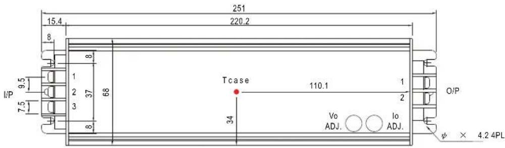
※T case: Max. Case Temperature.

natural_image
Technical line drawing of a rectangular structure with horizontal lines and two side supports, no text or symbols present.※Output voltage and constant current level can be adjusted through internalpotentiometer. (Can access by removing the rubber stopper on the case.)
AC Input Terminal Pin No. Assignment DC Output Terminal Pin No. Assignment
| Pin No. | Pin Assignment Assignment |
| 1 | FG 12 |
| 2 | AC/L +V |
| 3 | AC/N |
| 1 | -V |
| 2 |
D Type(option):(HLG-240H-_D)

※T case: Max. Case Temperature.

natural_image
Technical line drawing of a mechanical component with no visible text or symbols※IP67 rated. Timer dimming function, contact MEAN WELL for details.
■ Block Diagram
Fosc: 100KHz

flowchart
graph LR
    A["EMI FILTER & RECTIFIERS"] --> B["PFC CIRCUIT"]
    B --> C["POWER SWITCHING"]
    C --> D["RECTIFIERS & FILTER"]
    D --> E["+V"]
    D --> F["-V"]
    D --> G["DIM+"]
    D --> H["DIM-"]
    D --> I["(B Type)"]
    J["FG"] --> K["PFC CONTROL"]
    K --> L["O.L.P."]
    L --> M["PWM & PFC CONTROL"]
    M --> N["O.L.P."]
    N --> O["DETECTION CIRCUIT"]
    O --> P["O.V.P."]
    P --> Q["Ground"]
■ Derating Curve Static Characteristics

line
| AMBIENT TEMPERATURE (°C) | LOAD (%) | | ------------------------ | -------- | | -40 | 100 | | 50 | 100 | | 70 | 60 |

line
| INPUT VOLTAGE (V) | LOAD (%) | | ----------------- | -------- | | 90 | 80 | | 125 | 100 | | 150 | 100 | | 175 | 100 | | 200 | 100 | | 230 | 100 | | 305 | 100 |■ Power Factor Characteristic

line
| LOAD (240W) | 277Vac | 230Vac | 115Vac | | ----------- | ------ | ------ | ------ | | 50% | 0.85 | 0.91 | 0.99 | | 70% | 0.88 | 0.93 | 0.99 | | 90% | 0.91 | 0.95 | 0.99 | | 100% | 0.93 | 0.96 | 0.99 | | 240W | 0.94 | 0.97 | 0.99 |■ EFFICIENCY vs LOAD (48V Model)
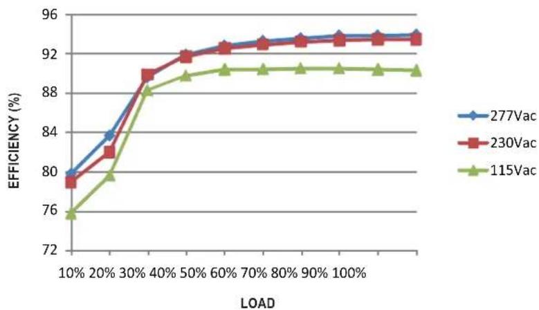
HLG-240H series possess superior working efficiency that up to 93.5% can be reached in field applications.
line
| LOAD | 277Vac | 230Vac | 115Vac | |-------|--------|--------|--------| | 10% | 80.0 | 79.5 | 76.0 | | 20% | 83.5 | 82.5 | 79.5 | | 30% | 88.0 | 89.0 | 88.0 | | 40% | 90.0 | 91.0 | 89.5 | | 50% | 91.5 | 92.0 | 90.5 | | 60% | 92.5 | 92.5 | 91.0 | | 70% | 93.0 | 93.0 | 91.0 | | 80% | 93.5 | 93.5 | 91.0 | | 90% | 93.5 | 93.5 | 91.0 | | 100% | 93.5 | 93.5 | 91.0 |■ DRIVING METHODS OF LED MODULE
There are two major kinds of LED drive method "direct drive" and "with LED driver".
A typical LED power supply may either work in "constant voltage mode (CV) or constant current mode (CC)" to drive the LEDs.
Mean Well's LED power supply with CV+ CC characteristic can be operated at both CV mode (with LED driver, at area (A) and CC mode (direct drive, at area (B)).

line
| Io (%) | Vo (min.) | | ------ | --------- | | 0 | 100 | | 100 | 50 | | 200 | 0 |In the constant current region, the highest voltage at the output of the driver depends on the configuration of the end systems.
Should there be any compatibility issues, please contact MEAN WELL.
Typical LED power supply I-V curve
■ DIMMING OPERATION (for B-type only)

※ Built-in 3 in 1 dimming function, IP67 rated. Output constant current level can be adjusted through output cable by connecting a resistance or 1 \~ 10Vdc or 10V PWM signal between DIM+ and DIM-.
※Please DO NOT connect "DIM-" to "-V".
※Reference resistance value for output current adjustment (Typical)
| Resistance value | Single driver | 10K Ω | 20K Ω | 30K Ω | 40KΩ | 50K Ω | 60K Ω | 70KΩ | 80K Ω | 90KΩ | 100KΩ | OPEN |
| Multiple drivers(N=driver quantity for synchronized dimming operation) | 10KΩ/N | 20KΩ/N | 30KΩ/N | 40KΩ/N | 50KΩ/N | 60KΩ/N | 70KΩ/N | 80KΩ/N | 90KΩ/N | 100KΩ/N | ---- | |
| Percentage of rated current | 10% | 20% | 30% | 40% | 50% | 60% | 70% | 80% | 90% | 100% | 95%~108% | |
※1 \~ 10V dimming function for output current adjustment (Typical)
| Dimming value | 1V 4V | 7V2V 5V | 8V3V 6V | 9V 10V | OPEN | ||||||
| Percentage of rated current | 10% | 20% | 30% | 40% | 50% | 60% | 70% | 80% | 90% | 100% | 95%~108% |
※10V PWM signal for output current adjustment (Typical): Frequency range :100Hz \~ 3KHz
| Duty value | 10% | 20% | 30% | 40% | 50% | 60% | 70% | 80% | 90% | 100% | OPEN |
| Percentage of rated current | 10% | 20% | 30% | 40% | 50% | 60% | 70% | 80% | 90% | 100% | 95%~108% |
※Using the built-in dimming function on B-type model can't turn the lighting fixture totally dark. Please refer to the connection method below to achieve 0% brightness of the lighting fixture connecting to the LED power supply unit.
※Direct connecting to LEDs is suggested, but is not suitable for using additional drivers.
Dimming connection diagram for turning the lighting fixture ON/OFF :

Using a switch and relay can turn ON/OFF the lighting fixture.
- Output constant current level can be adjusted through output cable by connecting a resistance or 1\~10Vdc or 10V PWM signal between DIM+ and DIM-.
- The LED lighting fixture can be turned ON/OFF by the switch.
WATERPROOF CONNECTION
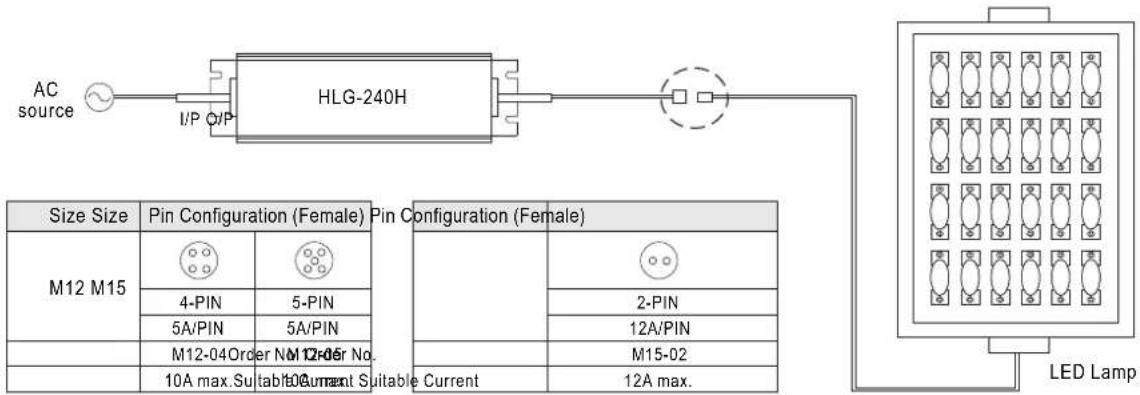
◎Waterproof connector
Waterproof connector can be assembled on the output cable of HLG-240H to operate in dry/wet/damp or outdoor environment.
flowchart
graph LR
    A["AC source"] --> B["I/P Q/P"]
    B --> C["HLG-240H"]
    C --> D["LED Lamp"]
    subgraph Size Size
        E["M12 M15"] --> F["Pin Configuration (Female)"]
        G["4-PIN"] --> H["Pin Configuration (Female)"]
        I["5A/PIN"] --> J["Pin Configuration (Female)"]
        K["M12-04 Order No. 10A max. Subtable 10 Current Suitable Current"]
    end
    subgraph Pin Configuration (Female)
        L["Pin Configuration (Female)"]
        M["Pin Configuration (Female)"]
        N["Pin Configuration (Female)"]
        O["Pin Configuration (Female)"]
        P["Pin Configuration (Female)"]
        Q["Pin Configuration (Female)"]
        R["Pin Configuration (Female)"]
        S["Pin Configuration (Female)"]
        T["Pin Configuration (Female)"]
        U["Pin Configuration (Female)"]
        V["Pin Configuration (Female)"]
        W["Pin Configuration (Female)"]
        X["Pin Configuration (Female)"]
        Y["Pin Configuration (Female)"]
        Z["Pin Configuration (Female)"]
    end
    style A fill:#f9f,stroke:#333
    style D fill:#ccf,stroke:#333
    style E fill:#cfc,stroke:#333
    style F fill:#fcc,stroke:#333
    style G fill:#fcc,stroke:#333
    style H fill:#fcc,stroke:#333
    style I fill:#fcc,stroke:#333
    style J fill:#fcc,stroke:#333
    style K fill:#fcc,stroke:#333
    style L fill:#cff,stroke:#333
    style M fill:#cff,stroke:#333
    style N fill:#cff,stroke:#333
    style O fill:#cff,stroke:#333
    style P fill:#cff,stroke:#333
    style Q fill:#cff,stroke:#333
    style R fill:#ffc,stroke:#333
    style S fill:#ffc,stroke:#333
    style T fill:#ffc,stroke:#333
    style U fill:#ffc,stroke:#333
    style V fill:#ffc,stroke:#333
    style W fill:#ffc,stroke:#333
©Cable Joiner

※CJ04 cable joiner can be purchased independently for user's own assembly.
MEAN WELL order No.: CJ04-1, CJ04-2.
◎Junction Box(Option)

※Optional junction box available for Apelaseelcontet MEAW WELL for details.
Marque : VELLEMAN
Modèle : HLG-240H-24B
Catégorie : Batterie