95-7320 - Accessoire automobile Metra - Notice d'utilisation et mode d'emploi gratuit
Retrouvez gratuitement la notice de l'appareil 95-7320 Metra au format PDF.


| Type de produit | Kit d'installation de radio autoradio |
| Marque | Metra |
| Modèle | 95-7320 |
| Matériau | Plastique ABS moulé |
| Couleur | Noir mat |
| Dimensions (approx.) | 178 x 102 mm (standard DIN simple) |
| Poids | Environ 150 g |
| Alimentation | Aucune (passif) |
| Fonctions principales | Adaptateur de tableau de bord pour montage d'autoradio aftermarket |
| Contenu du kit | Plaque de montage, supports de fixation, vis et instructions |
| Compatibilité véhicule | Véhicules sélectionnés (consulter la notice) |
| Installation | Facile, nécessite des outils de base (tournevis, démonte-panneaux) |
| Entretien et nettoyage | Nettoyer avec un chiffon doux et sec |
| Sécurité | Couper l'alimentation du véhicule avant installation |
| Pièces détachées et réparabilité | Pièces de rechange disponibles auprès du fabricant |
| Informations générales | Garantie 1 an |
FOIRE AUX QUESTIONS - 95-7320 Metra
Questions des utilisateurs sur 95-7320 Metra
0 question sur cet appareil. Repondez a celles que vous connaissez ou posez la votre.
Poser une nouvelle question sur cet appareil
Téléchargez la notice de votre Accessoire automobile au format PDF gratuitement ! Retrouvez votre notice 95-7320 - Metra et reprennez votre appareil électronique en main. Sur cette page sont publiés tous les documents nécessaires à l'utilisation de votre appareil 95-7320 de la marque Metra.
MODE D'EMPLOI 95-7320 Metra
User Manual of Product 1:
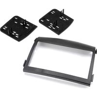
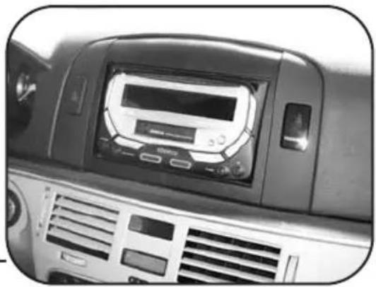
Metra 95-7320 Double DIN Installation Dash Kit for 2006-2008 Hyundai Sonata -Black
INSTALLATION INSTRUCTIONS FOR PART 95-7320
APPLICATIONS
Hyundai Sonata 2006-2008
95-7320
KIT FEATURES
• Double DIN Radio Provision
- Stacked ISO Mount Units Provision
KIT COMPONENTS
A) Double DIN Trim Plate B) Double DIN Brackets


TOOLS REQUIRED:
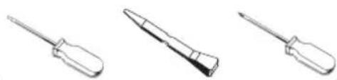
Small Flat Blade Screwdriver • Panel Removal Tool • Phillips Screwdriver

1-800-221-0932

www.metraonline.com
TABLE OF CONTENTS
Dash Disassembly
- Hyundai Sonata 2006- 2008 ....1
Kit Assembly
- Double DIN or Stacked ISO Mount Units Provision .... 2
Final Assembly 3
*Note:
Refer also to the instructions included with the aftermarket radio.
HYUNDAI SONATA 2006-2008
1 Disconnect the negative battery terminal to prevent an accidental short circuit.
2 Open glove box and remove (2) Phillips screws from top edge of glove box opening and bottom edge of wood trim below radio. (Figure A)
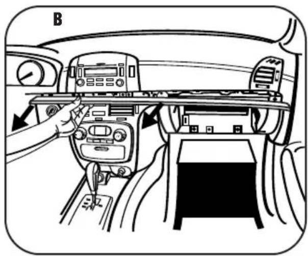
3 Unclip and remove wood trim from below radio and above glove box. (Figure B)
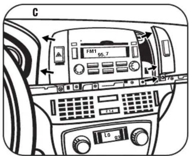
4 Remove (1) Phillips screw securing each side panel next to radio then unclip and remove the panels. (Figure C)
5 Remove (6) Phillips screws securing the radio. Unplug and remove the radio. (Figure D)
NOTE: There is a factory support bracket in the bottom of the radio cavity that may need to be pushed out of the way for the aftermarket radio to fit properly.
Continue to kit assembly.


DOUBLE DIN OR
STACKED ISO MOUNT UNITS PROVISION
*Note: Refer also to the instructions included with the aftermarket radio.
1 Snap the Double DIN brackets to the inside edge of the Double DIN Trim Plate. (Figure A)
2 Slide the Double DIN or stacked ISO mount unit(s) into the bracket/trim plate assembly and secure the unit(s) to the assembly using the screws supplied with the unit(s). (Figure B)
Continue to final assembly.


FINAL ASSEMBLY

(A) Strip wire ends back 1/2"
B) Twist ends together
C) Solder
D) Tape
1 Locate the factory wiring harness in the dash. Metra recommends using the proper mating adapter and making connections as shown. (Isolate and individually tape off the ends of any unused wires to prevent electrical short circuit.)
2 Re-connect the negative battery terminal and test the unit for proper operation.
3 Reassemble radio and dash assemblies in reverse order of disassembly.
FINAL WIRING CONNECTIONS
Make wiring connections using the EIA color code chart shown below and the instructions included with the head unit. Metra recommends making connections as shown below; Strip, Splice, Solder, Tape. Isolate and individually tape off ends of any unused wires to prevent electrical short circuit.
METRA / EIA WIRING CODE
| 12V Ignition / Acc. . . . . . . . . Red | Right Front (+) . . . . . . . . . . . . . . . . . . . . . . . . . . . . . . . . . . . . . . . . . . . . . . . . . . . . . . . . . . . . . . . . . . . . . . . . . . . . . . . . . . . . . . . . . . . . . . . . . . . . | ||
| 12V Batt / Memory. . . . . . . . . . . . Yellow | Right Front (-). . . . . . . . . . . . . . . . . . . . . . . . . . . . . . . . . . . . . . . . . . . . . . . . . . . . . . . . . . . . . . . . . . . . . . . . . . . . . . . . . . . . . . . . . . . . . . . . . . . . Ground. . . . . . . . . . . . . . . . . . . . . . . . . . . . . . . . . . . . . . . . . . . . . . . . . . . . . . . . . . . . . . . . . . . . . . . . . . . . . . . . . . . . . . . . . . . . . . . . . . . . Power Antenna. . . . . . . . . . . . . . . . Blue | Left Front (+) . . . . . . . . . . . . . . . . . . . . . . . . . . . . . . . . . . . . . . . . . . . . . . . . . . . . . . . . . . . . . . . . . . . . . . . . . . . . . . . . . . . . . . . . . . Left Front (-). . . . . . . . . . . . . . . . . . . . . . . . . . . . . . . . . . . . . . . . . . White | |
| Amp Turn-On. . . . . . . . . . . . . . . . . Blue / White | Right Rear (+) . . . . . . . . . . . . . . . . . . . . . . . . . . . . . . . . . . . . . . . . . . . . . . . . . . . . . . . . . . . . . . . . . . . . . . . . Amp Ground. . . . . . . . . . . . . . Black / White | Right Rear (-) . . . . . . . . . . . . . . . . . . . . . . . . . . . . . . . . . . . . . . . . . . . . . . . . . . . . . . . . . . . . . . . . . . . . . . . Illumination. . . . . . . . . . . . Orange | Right Rear (-) . . . . . . . . . . . . . . . . . . . . . . . . . . . . . . . . . . . . . . . . . . . . . . . . . . . . . . . . . . . . . . . . . . . . . . . . . . . . . . . . . . . . . . . . . . . . . . Dimmer. . . . . . . . . . . . . Orange / White |
| Left Rear (+) . . . . . . . . . . . . . . . . . . . . . . . . . . . . . . . . . . . . . . . . . . . . . . . . . . . . . . . . . . . . . . . . . . . . . . . . . . . . . . . . . . . . . . . . . . . . . . . . . |
*NOTE: When a Black wire is not present, ground radio to vehicle chassis.
All colors may not be present on all leads due to manufacturer's specifications.
NOTES
NOTES
95-7320 INSTRUCTIONS
Marque : Metra
Modèle : 95-7320
Catégorie : Accessoire automobile