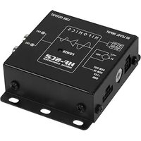
HF-SC2 - Convertisseur audio Hifonics - Notice d'utilisation et mode d'emploi gratuit
Retrouvez gratuitement la notice de l'appareil HF-SC2 Hifonics au format PDF.


| Type de produit | Amplificateur 2 canaux / Système de haut-parleurs |
| Marque | Hifonics |
| Modèle | HF-SC2 |
| Dimensions (L x l x H) | 200 x 150 x 50 mm |
| Poids | 1,2 kg |
| Alimentation | 12 V CC (installation automobile) |
| Puissance de sortie RMS | 2 x 50 W sous 4 ohms |
| Impédance | 4 ohms (compatible 2 ohms en pont) |
| Réponse en fréquence | 20 Hz - 20 kHz |
| Rapport signal/bruit | > 90 dB |
| Fonctions principales | Amplification stéréo, filtrage passe-haut/passe-bas réglable, protection thermique et court-circuit |
| Entrées | 2 x RCA, haut niveau (connecteur enfichable) |
| Sorties | 2 x bornes à vis (enceintes) |
| Entretien et nettoyage | Nettoyer avec un chiffon doux et sec. Ne pas utiliser de liquides agressifs. |
| Sécurité | Protection contre les courts-circuits, la surchauffe et la surtension. Coupure automatique en cas de défaut. |
| Pièces détachées et réparabilité | Contacter le service après-vente agréé Hifonics pour toute réparation ou remplacement. |
| Informations générales | Utilisation uniquement sur des installations 12 V CC. Respecter la polarité et les sections de câble recommandées. |
FOIRE AUX QUESTIONS - HF-SC2 Hifonics
Questions des utilisateurs sur HF-SC2 Hifonics
0 question sur cet appareil. Repondez a celles que vous connaissez ou posez la votre.
Poser une nouvelle question sur cet appareil
Téléchargez la notice de votre Convertisseur audio au format PDF gratuitement ! Retrouvez votre notice HF-SC2 - Hifonics et reprennez votre appareil électronique en main. Sur cette page sont publiés tous les documents nécessaires à l'utilisation de votre appareil HF-SC2 de la marque Hifonics.
MODE D'EMPLOI HF-SC2 Hifonics
HIFONICS
HF-SC2
2-KANAL SIGNAL KONVERTER
BESTIMMUNGSGEMÄSSER GEBRAUCH
Dieses Gerät ist nur für den Gebrauch in Fahrzeugen mit +12V Stromversorgung und negativer Masse geeignet. Das Gerät dient dazu, die Hochpegelsignale der Lautsprecherausgänge eines Steuergeräts/Autoradios in Vorverstärkersignale (Niederpegelsignale) zu konvertieren, damit diese an weiteren Audiogeräten wie Verstärkern oder Prozessoren benutzt werden können.
INSTALLATIONSHINWEISE
Klemmen Sie sicherheitshalber vor Installation des Geräts den Massepol Ihr Fahrzeugbatterie ab, um Kurzschlüsse und Stromschläge zu vermeiden. Achten Sie darauf, dass das Gerät sicher befestigt wird und bei der Montage keine wichtigen Komponenten des Fahrzeugs beschädigt werden.

Bitte achten Sie beim Anschliessen stets auf die korrekte Polarität aller Anschlüsse!

flowchart
graph TD
    A["Lautsprechereingänge Kanal 1/2 Hochpegelsignal (bis 10V/RMS)"]
    B["Einschaltoption"]
    C["Stromversorgung Einschaltsignal"]
    D["Vorverstärkerausgänge Kanal 1/2 Niederpegelsignal"]
    E["EPS Schutzschaltung"]
    A --> F["HI LEVEL INPUT"]
    B --> G["Line OUTPUT"]
    C --> H["POWER LED"]
    D --> I["Power LED"]
    F --> J["HIFONICS"]
    G --> K["HF-SC2 SIGNAL CONVERTER"]
    H --> L["Power LED"]
    I --> M["Line OUTPUT"]
    J --> N["Line OUTPUT"]
    K --> O["Line OUTPUT"]
    style A fill:#f9f,stroke:#333
    style B fill:#f9f,stroke:#333
    style C fill:#f9f,stroke:#333
    style D fill:#f9f,stroke:#333
    style E fill:#f9f,stroke:#333
    style F fill:#ccf,stroke:#333
    style G fill:#ccf,stroke:#333
    style H fill:#ccf,stroke:#333
    style I fill:#ccf,stroke:#333
STECKBRÜCKE FÜR „SCHWEBENDE“ MASSE
Sollten unerwartet Störgeräusche von der Lichtmaschine zu hören sein, können Sie die angeschlossene Masse des Fahrzeugs vom Vorverstärkersignal trennen. Klemmen Sie dafür zuerst den Kabelstecker der Stromversorgung am Gerät ab und öffnen dann vorsichtig das Gehäuse mittels geeignetem Werkzeug.
Im Geräteinnern befindet sich eine kleine Steckbrücke rechts unten. Ziehen mit einer Zange vorsichtig die Steckbrücke heraus und stecken sie auf die Position OFF ein. Dadurch wird eine schwebende Masse (Floating Ground) erzeugt.
Bauen Sie danach das Gehäuse wieder zusammen und schließen das Gerät zum Betrieb wieder an.

HIFONICS
HF-SC2
2-CHANNEL SIGNAL CONVERTER
INTENDED USE
This device is only suitable for use in vehicles with + 12V power supply and negative ground. The device is used to convert the high-level signals from the loudspeaker outputs of a head unit / car radio into preamplifier signals (low-level signals) so that these can be used on other audio devices such as amplifiers or processors.
INSTALLATION INSTRUCTIONS
To be on the safe side, disconnect the ground terminal of your vehicle battery before installing the device in order to avoid short circuits and electric shocks. Make sure that the device is securely attached and that no important components of the vehicle are damaged during installation.

When connecting, please ensure that all connections have the correct polarity!

flowchart
graph TD
    A["Speaker Inputs\nChannel 1/2\nHigh Level Signal (until 10V/RMS)"] --> B["HI LEVEL INPUT"]
    C["Turn-On Options"] --> D["Power Supply\nTurn-on Signal\nConnect the cables accordingly to the enclosed cable connector."]
    D --> E["Power LED\nIf this lights up, the device is ready for use."]
    F["Pre-amplifier Outputs\nChannel 1/2\nLow Level Signal"] --> G["HIFONICS"]
    G --> H["POWER\nHF-SC2\nSIGNAL CONVERTER"]
    I["EPS Protection Circuit"] --> J["Power OUT\nTurn-on signal output of the generated turn-on signal for other devices such as amps or processors."]
    J --> K["REM IN\nTurn-on signal of the head unit / car radio +12V +12 volt power connection: The positive +12 V cable MUST be secured with a separate 3A cable fuse."]
    K --> L["GND Ground connection: Connect this to a suitable ground point in the vehicle."]
    M["Line OUTPUT"] --> N["CH1 CH2 CH1+CH2"]
    N --> O["TOB-08 DC VOX"]
    O --> P["REM OUT REM IN +12V GND"]
    P --> Q["Power LED\nIf this lights up, the device is ready for use."]
JUMPER FOR FLOATING GROUND
If you unexpectedly hear interference from the alternator, you can disconnect the connected ground of the vehicle from the pre-amplifier signal. To do this, first disconnect the power supply cable plug from the device and then carefully open the housing using a suitable tool.
There is a small jumper inside the device at the bottom right. Carefully pull out the jumper with a pair of pliers and insert it in the OFF position. This creates a floating ground.
Then reassemble the housing and reconnect the device for operation.

Marque : Hifonics
Modèle : HF-SC2
Catégorie : Convertisseur audio