GTX47 - Équipement audio JBL - Notice d'utilisation et mode d'emploi gratuit
Retrouvez gratuitement la notice de l'appareil GTX47 JBL au format PDF.


| Type de produit | Haut-parleur de graves (subwoofer) pour voiture |
| Marque | JBL |
| Modèle | GTX47 |
| Dimensions (diamètre) | 165 mm (6,5 pouces) |
| Profondeur de montage | 55 mm |
| Puissance maximale | 500 W |
| Puissance RMS | 200 W |
| Impédance | 4 ohms |
| Réponse en fréquence | 35 Hz – 200 Hz |
| Matériau du cône | Polypropylène traité |
| Matériau de la suspension | Caoutchouc |
| Profondeur de montage | 55 mm |
| Poids | 1,8 kg |
| Alimentation | Via amplificateur externe (non inclus) |
| Utilisation recommandée | Caisson de basses dans une voiture |
| Fonctions principales | Reproduction des basses fréquences pour un son plus profond |
| Accessoires inclus | Joint d'étanchéité, vis de montage, notice |
| Entretien et nettoyage | Dépoussiérer avec un chiffon sec ; éviter l'humidité |
| Installation | Montage dans une enceinte ou directement dans la plaque de la voiture |
| Sécurité | Ne pas dépasser la puissance RMS ; vérifier la fixation |
| Réparabilité | Pièces détachées disponibles auprès du SAV JBL (cône, suspension, bobine) |
FOIRE AUX QUESTIONS - GTX47 JBL
Questions des utilisateurs sur GTX47 JBL
0 question sur cet appareil. Repondez a celles que vous connaissez ou posez la votre.
Poser une nouvelle question sur cet appareil
Téléchargez la notice de votre Équipement audio au format PDF gratuitement ! Retrouvez votre notice GTX47 - JBL et reprennez votre appareil électronique en main. Sur cette page sont publiés tous les documents nécessaires à l'utilisation de votre appareil GTX47 de la marque JBL.
MODE D'EMPLOI GTX47 JBL
GTX47
ACTIVE DIVIDING NETWORK
OWNER'S MANUAL
JBL


Table Of Contents
| Specifications | 3 |
| Features | 4 |
| Theory of Operation | 5 |
| Controls, Connectors and Switches | 10 |
| Mounting Instructions | 14 |
| Wiring and Set-up | 20 |
| Adjustments | 21 |
Owner's Warranty Information Records
| Model Number | |
| Serial Number | |
| Dealer Name | |
| City, State, Zip | |
| Sales Receipt Number | |
| Date of Purchase |
Specifications
| Number of Outputs | 7 (fully configurable) |
| Possible System Configurations | FRONT: 1, 2 or 3-wayREAR: 1, 2 or 3-waySUBWOOFER |
| Crossover Section Frequencies | LOW: (SUBWOOFER)Low-Pass 30 - 300HzFRONT AND REAR MID 1:High-Pass Filter: 30Hz - 300HzLow-Pass Filter (x1 mode): 100Hz - 1kHz(x10 mode): 1kHz - 10kHzFRONT AND REAR MID 2:High Pass 100 - 1kHzLow Pass 1k - 10kHzFRONT AND REAR HIGH:High Pass (x1 mode): 1kHz - 10kHz(÷20 mode): 50Hz - 500Hz |
| Output Level Control Range | 0dB to -20dB |
| Overall Frequency Response | 10Hz to 50kHz (+0dB, -1dB) |
| Signal-to-Noise Ratio | 100dBA |
| Input Sensitivity (for 500mV output, Gain Control CW) | 500mV |
| Maximum Line Level Input: | 4V RMS |
| Line Level Input Impedance | 10kΩ MIN. |
| Output Impedance | 1kΩ MAX. |
| Speaker Level Input Impedance: | 15Ω |
| Maximum Speaker Level Input: | 7V RMS |
| Filter Type | Subwoofer: Selectable (18dB or 24dB per octave)All Others: (12dB per octave Butterworth) |
| Size (W x L x H) | |
| Main Chassis: | 117/8 × 71/8 × 15/8 "300mm x 180mm x 41mm |
| Remote Unit: | 2.56" x 3.3" x 1.18"(65mm x 64mm x 30mm) |
| Weight | |
| Main Chassis: | 3 lbs. 14 oz. (1.76kg) |
| Remote Unit: | 8.5 oz. (240g) |
Features
- Variable frequency crossover combined with unique "Virtual Center" image enhancement circuitry.
- Trunk-mount design with dash-mount remote control.
- Separate Front and Rear inputs.
- Configurable to 2, 3, or 4-way operation with independent front and rear channel adjustments.
• Continuously adjustable crossover frequencies independently adjustable for each band. - Constant-bass (non-fading) Subwoofer output.
-
"Phase" switches on each output allow easy polarity reversal to assure optimum band-to-band transitions.
-
Stereo / Mono Subwoofer output selection.
- 12dB per octave crossover slopes on all bands.
- Selectable 18db or 24dB slope Subwoofer filter.
- "Virtual Center" image enhancement circuit both stabilizes the center image for the driver and recovers rear channel ambiance.
- Remote control provides adjustment for effects level and bypass modes.
- Small car / large car image optimizer switch.
• Gold-plated connectors eliminate contact oxidation and assure reliable trouble-free connections.
Theory of Operation
Why Crossover Networks are Needed If a single speaker could be made to cover the entire frequency range with smooth response, low distortion, and high output, and be small enough to fit in a car, we would not need crossover networks of any type. Unfortunately, no one has yet developed the "perfect" speaker that has all of these ideal characteristics. As a result, multiple drivers, each specialized for a band of frequencies, are generally used to cover the audible frequency range. The cross-over network's job is to divide the full-spectrum music signal into the narrow bands required by each specialized speaker driver. A 2-way speaker separates the frequency spectrum into 2-bands typically handled by a Woofer and Tweeter which reproduce the lows and highs respectively. 3-way systems add a Midrange driver, and 4-way systems commonly add either a Midbass driver or super-tweeter. The GTX47 has the unique flexibility to adapt to any system from 2 to 4-way designs, both front and rear, and with independent adjustment for each band.
![graph TD A["Source"] --> B["GTX47 Active Crossover"] B --> C1["To Tweeters"] B --> C2["To Midrange"] B --> C3["To Mid-Bass"] B --> C4["To Subwoofer"] C1 --> D1["/4"] C2 --> D2["/3"] C3 --> D3["/2"] C4 --> D4["/1"] style A fill:#f9f,stroke:#333 style B fill:#ccf,stroke:#333 style C1 fill:#cfc,stroke:…](/content/2026/06/1388609/images/e3984dfb92d4e8e861015825b50cb978a47a94c6497e9c2931f97545f5c1e608.jpg)
Understanding the Terminology There are three basic types of crossover circuits used in the GTX47: High-Pass, Low-Pass, and Band-Pass. As its name implies, a Low-Pass crossover allows low frequencies to pass through, and blocks higher ones. In the GTX47, a Low-Pass crossover is commonly used for the Subwoofer, and is labeled "LOW." A High-Pass crossover allows high frequencies to pass through and blocks the lows. In the GTX47, two high-pass sections are included, labeled "FRONT HIGH" and "REAR HIGH." By proper use of the frequency controls, these may be used to feed either a front or rear satellite speaker or the tweeters in a 3 or 4-way system. The remaining sections, "FRONT and REAR MID 1 and MID 2," are Band-Pass crossovers, where both the highs and lows are blocked, and the band in the middle is allowed to pass through. These are typically used for Midrange or Midbass speakers. The crossover circuits of the GTX47 may be used in a variety of combinations to create 2, 3, or 4-way designs independently for front and rear systems.
![graph TD A["Low-Pass"] --> B["+"] C["High-Pass"] --> B D["Bandpass"] --> E["="] F["Increasing Frequency"] --> E](/content/2026/06/1388609/images/a124cfebfaafdf5ca6f481225feb26a203d5a024446b37b0e90cf97d97d13b64.jpg)
JBL
The rate at which the crossover attenuates the out-of-band signals is called the slope. In the GTX47, the slope of all of the Band-Pass and High-Pass sections is 12dB per octave. This means that the output of the signal will be attenuated by 12dB for each octave away from the Cutoff Frequency. As in all crossovers, there is still signal which reaches the speaker outside of the frequencies passed by the crossover, but this signal is increasingly attenuated the further away it is from the desired band. The slope of the subwoofer ("LOW") section in the GTX47 may be chosen as 18 or 24 dB per octave. The sharper 24dB per octave slope is helpful to reduce the amount of Midrange energy produced by the subwoofer, improving system imaging.
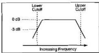
The Cutoff Frequency for each band is the point at which the response is 3dB down from the signal level. On the GTX47, the Cutoff Frequency of each High-Pass and Low Pass is adjustable. Each Band-Pass has adjustments for both the upper and lower Cutoff Frequencies which define the band.
![graph TD A["HEAD UNIT"] -->|Level Output| B["POWER AMP"] B -->|Speaker Level Output| C["PASSIVE DIVIDING NETWORK"] C --> D["SPEAKERS"] C --> E["Speaker Level Outputs"]](/content/2026/06/1388609/images/1b71c5791b38877f767f5f1d32b4ee9425bf9e53e557702a8cce8805db228895.jpg)
Passive Crossovers
Passive crossovers are the most common type of crossover. The "passive" nomenclature results from the fact that they are made up from non-powered components such as capacitors, inductors, and resistors. They are inserted between the amplifier and the speaker components and act on the amplified speaker output of the amp. When you buy a 2-way speaker system, some form of passive crossover is usually part of the package, either built in to the speaker as in most coaxial designs, or as an outboard unit.
Passive crossovers can be cost-efficient and generally allow the simplest system wiring. They also allow the use of one amplifier to drive the entire system. They do, however, have a number of disadvantages.
- Passive crossovers are inefficient: A considerable amount of power is dissipated by the passive crossover components before reaching the speakers.
![graph TD A["Source"] --> B["GTX47 Active Crossover"] B --> C1["To Tweowers"] B --> C2["To Midrange"] B --> C3["To Mid-Bass"] B --> C4["To Subwoofers"] C1 --> D1["√4"] C2 --> D2["√5"] C3 --> D3["√6"] C4 --> D4["√7"] D1 --> E1["Low Pass Filter "Low""] D2 --> E2["Band Pass Filter "Mid&qu…](/content/2026/06/1388609/images/183f0099f438bfc1d2d67c9cdcee8106ab71b1aef45e560010dcb1c4de848ba6.jpg)
JBL
- Potential tweeter damage: Bass and Midrange contain significantly more energy than high frequencies. As a result, the system's amplifier is more likely to reach its limits and "Clip" from Bass or Midrange signals than from Treble. A result of clipping is that full-power high frequency energy is produced by the amplifier far in excess of that produced by any natural musical demand. This energy passes through the crossover and reaches the tweeter which not only sounds pretty bad, but is also likely to destroy the tweeter's voice coil.
- High cost for steep slopes: Most passive crossovers used in car audio have only a 6dB per octave slope. This is because the size and cost of the high-power inductors needed for steeper slopes with high accuracy and low power loss make more elaborate designs expensive and difficult to install. Compared to the 12dB per octave slopes of the GTX47, a 6dB passive crossover lets each driver receive more undesired out of band signals. This not only detracts from the sound, but also reduces the power handling and dynamic range of the system.
Active Crossovers
An active crossover uses active components such as op-amps and transistors to derive crossover filters which divide the signal ahead of the power amplifiers, while the signal is still at preamp level. An amplifier channel is then pro-
vided for each individual speaker component, eliminating the need for passive crossovers between the amp and speaker. By using separate amplifier channels the drivers are completely isolated from each other, and from the crossover. This provides a number of advantages.
- Power loss is eliminated: Because there is nothing between the amplifier and speaker, all of the amplifier's power can be delivered most efficiently to each speaker.
- The system is adjustable: Each speaker has its own amplifier gain control and its own cutoff frequency adjustments. Level imbalances between different speakers are overcome by simply varying the level control on each amplifier. The system can be fine tuned perfectly for nearly any reasonable combination of components.
-
The system is more reliable: The power supplied to each driver can be scaled to the needs of the specific frequency band. Multiple small amplifier channels will play louder and more clearly than two more powerful channels which add up to the same total system power. In addition, if a bass or Midrange amplifier "Clips," the resulting distortion will not reach the tweeter, adding up to better sound and no tweeter damage.
-
Greater precision: Because the frequency-dependent loudspeaker impedance is isolated from the load by the power amplifiers, the crossover's performance characteristics are precise and predictable.
- Competitive cost: While passive crossovers are cost-effective in simple configurations, Multichannel amplifiers used with versatile active crossovers like the GTX47 make sophisticated active systems the same or less to build than passive systems of similar complexity and total power.
For these reasons, active crossovers are used almost exclusively in demanding professional concert sound and studio applications. They are also by far the best way to build the optimum car audio system.
Theory of Operation – Virtual Center Image Enhancer.
Many methods have been tried to recreate the image and spaciousness of a live performance in the confines of a car interior. Multichannel surround sound, DSP, installing a center channel speaker, sophisticated phase and amplitude manipulation, and other approaches can help add to the realism of reproduced sound when applied properly. When misapplied, the results can be disastrous. Until the JBL Virtual Center circuitry was developed, the most suc-
cessful techniques were expensive, as with DSP, or often required difficult installation, as with center channel speakers.
JBL's breakthrough "Virtual Center" circuitry is the result of the understanding of how the human ear responds to timing, frequency, and amplitude cues to determine the apparent direction of a sound source. Virtual Center circuitry manipulates the analog signal in real time to provide each of the driver's ears with the signal they would receive if the driver was seated in the center of the vehicle. This provides a stable centered image to the driver much like that obtained with a dedicated center-channel loudspeaker.
To restore the spaciousness that is generally lost in the small confines of a car interior, the rear channels utilize differential-mode ambiance recovery to restore the ambiance information present in all conventional stereo recordings. Unlike DSP, the JBL circuitry does not add synthetic reverb, but recovers real information that is masked in conventional systems. As a result, the overall effect from the Virtual Center circuitry of the GTX47 is incredibly realistic yet simple to adjust and use. Best of all, the "Virtual Center" and ambiance recovery circuits do not require specially encoded recordings and work with virtually all conventional stereo tapes, discs, and broadcasts.
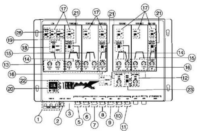
Controls, Connectors and Switches
- Power Connectors: Connect to Battery, Ground and Remote-On signals.
- The Battery terminal should be connected directly to the battery. Do not connect this terminal to the vehicle's electrical system wiring (such as dome-light circuit, etc.). Add a 3-Amp inline fuse (not included) to protect against shorting of the power wire.
-
The Ground terminal connection should be made to a clean, bare metal part of the vehicle's chassis (an already installed screw, if possible). Scrape off paint or corrosion from this grounding point.
-
The Remote-On terminal should be connected to the remote turn-on wire or power antenna output from the head unit. This will allow the GTX47 to turn on and off simultaneously with the head unit.
-
Fuse: The fuse protects the unit from damage. If the unit's remote-on light does not turn on, check this fuse. If the fuse has blown, replace it with a new one of the same value (do not use larger value fuses). If the fuse blows again, there is a problem with the wiring and/or the unit itself. Your JBL dealer can identify and correct the problem.
-
Remote Control Connector: Plug the remote control cable into this receptacle.
- High and Low Level Input Connectors: When using a head unit with separate front and rear 4-channel preamp-level outputs, connect the front and rear head unit outputs to the front and rear line level inputs respectively. The input selector switch (23) should be in the "Front & Rear" Position. If using a head unit with just 2-channel preamp output, connect the head-unit to the "Front" line level inputs and switch the input mode switch to "Front Only." If using a head unit which only has speaker level outputs, connect the head unit outputs to the speaker level inputs with the supplied adapter cable. Set the input mode selector to "Front" for a 2-channel head unit and "Front and Rear" for 4-channel units. If you are using a bi-level head unit which has 2-channels of line level and 2-channels of speaker level, both the 2-channels of line level input and 2-channels of speaker level input may be used. In this case, the input mode selector should be set to the "Front & Rear" position.
- "Low" Output Connectors: Connect to the subwoofer amplifier input terminals.
-
Front Mid 1 Output Connectors: Connect to the amplifier used to drive front channel Midrange or Midbass loudspeakers in 3 or 4-way systems.
-
Front Mid 2 Output Connectors: Connect to the amplifier used to drive Midrange speakers in 3 or 4-way systems.
NOTE: Either Mid 1 or Mid 2 may be used for the Midrange driver in 3-way systems depending on the crossover frequency desired. - Front High Output Connectors: Connect to the amplifier used for the front tweeters in 3 or 4-way systems or to the front satellite speakers in 2-way systems.
- Rear Mid 1 Output Connectors: Connect to the amplifier used to drive rear channel Midrange or Midbass loudspeakers in 3 or 4-way systems.
- Rear Mid 2 Output Connectors: Connect to the amplifier used to drive rear Midrange speakers in 3 or 4-way systems.
NOTE: Either Mid 1 or Mid 2 may be used for the Midrange driver in 3-way systems depending on the crossover frequency desired.
- Rear High Output Connectors: Connect to the amplifier used for the rear tweeters in 3 or 4-way systems or to the rear satellite speakers in 2-way systems.
- Front and Rear Channel Gain Controls: Use these controls to set
the input sensitivity level of the GTX47 to the optimal level for connection to the amplifiers.
- Right and Left Low Output Frequency Adjustment Controls: Use these controls to set the upper cutoff frequencies for the LOW output.
- Front and Rear Mid 1 Cutoff Frequency Adjustments: These controls set the upper and lower cutoff frequencies of the Mid1 band-pass filters. Use the control labeled HPF to set the low frequency limit and the control labeled LPF to set the upper frequency limit.
- Front and Rear Mid 2 Cutoff Frequency Adjustments: These controls set the upper and lower cutoff frequencies of the Mid 2 band-pass filters. Use the control labeled HPF to set the low frequency limit and the control labeled LPF to set the upper frequency limit.
- Front and Rear High Frequency Adjustment Controls: Use these controls to set the lower cutoff frequency of the Front and Rear High outputs.
- Phase Switches: These switches reverse the polarity of the speakers connected to their respective outputs. Start by setting these switches to 0 to keep all of the outputs "in-phase." If an RTA shows a deep dip
in response at any of the crossover frequencies, try reversing the polarity of one of the drivers at this crossover. If the dip is reduced or eliminated, leave the phase switch in this position. Check each band and leave the phase switches in the position which gives the smoothest response.
- "Low" Crossover Slope: Use this switch to set the "Low" output crossover slope to either 18 or 24dB per octave.
- Subwoofer Output Stereo/Mono Switch: Selects Stereo or Mono output for the sub-bass frequencies. The Mono mode allows the use of one subwoofer along with a single channel amplifier. It should also be used when two or more subwoofers are mounted in a common enclosure or baffle board. The Stereo mode can provide better separation when independent and isolated enclosures are used for each subwoofer.
- Remote-On Indicator: An LED gives visual confirmation of whether or not the unit is in operation. It is also useful for system trouble-shooting.
- Crossover Frequency Multiplier Switches: These switches can
change the range of crossover frequencies. The alternate multiplied frequency adjustment ranges are listed above the variable controls.
NOTE: The High crossover replaces the frequency multiplier with a ÷20 frequency divider to be used in 2-way or some 3-way systems.
- Car Size Optimizer Switch: Use this switch to optimize the phantom center image position on the built in Imaging enhancer processor.
- Input Mode Switch: Set this switch to "Front Only" when using the GTX47 with a head unit that has only one set of outputs. This causes the front and rear crossover sections to be driven by the front input signal. Set this switch to Front and Rear when using the GTX47 with a head unit that has two sets of outputs.
- Remote Bypass/On Indicator: This indicator is on when the Imaging Processor is engaged and off when the Imaging Enhancer is bypassed.
-
Driver/All Optimizer Indicator: This indicator is on when the Imaging Enhancer is in "Driver" optimization mode and off when the Imaging Enhancer is in the "All" passenger mode.
-
Front Ambience and On/Bypass Control and Switch: Rotating this control adjusts the amount of ambience and front staging width produced by the Imaging Enhancer. Pulling the knob places the Imaging in "Bypass" mode. Pushing in the knob places the Imaging Enhancer in "On" mode.
- Rear Ambience and Driver/All Optimizer Control: Rotating this knob controls the amount of rear fill ambience and the "room size" of the acoustic environment when used in a system with rear speakers. Pulling the knob out places the Imaging Enhancer in "All" passengers optimization mode. Pushing the knob in places the unit in "Driver" optimization mode. Best results at the drivers position will be achieved with the control in the "Driver" setting.
- Subsonic Filter Switch: Engages a 5Hz High Pass subsonic filter.

JBL
Mounting Instructions
Mount the GTX47 in a location that allows reasonable access for future adjustment changes, should they become necessary due to system expansion or modification. This unit can be placed inside the trunk, under the seat or underdash. However, to avoid unnecessary signal wiring, it is better to mount the GTX47 as close as possible to the amplifiers.
If the permanent mounting location will not allow changes in the adjustment of the controls, the rest of the sound system must be completely installed, and all the adjustments to the GTX47 should be made before it is permanently mounted in its location. Input and output wires may be temporarily extended in order to have the unit in a more accessible position for adjustment. Choosing a readily accessible location will save having to remove the unit in order to revise any of its adjustments.
DO NOT MOUNT THE UNIT IN LOCATIONS THAT WILL BE IN THE VICINITY OF MOISTURE OR EXTREME HEAT (such as the engine compartment).
The GTX47 can be mounted by using self-tapping screws. Make sure you have all the necessary parts and tools, then begin mounting according to one of the following procedures:
NOTE: Before mounting, record the serial number (located on the bottom of the unit) in the space provided on the front cover of this manual for future reference.
Screw-down Mounting:
- Hold the GTX47 at its mounting location and mark screw holes. Make sure that there are no objects behind the surface where holes are to be made that may become damaged.
- Drill holes and secure the unit with self-tapping screws supplied.



Remote Chassis Installation
The wired remote of the GTX47 can be installed either in dash or under dash.
Under dash remote installation
1. Set the GTX47 remote in the installation location and mark two mounting screw hole locations.
2. Set the GTX47 remote aside and drill two pilot holes using a 1/16 (1mm) bit. Be careful not to drill into any of the car's components.
3. Secure the spacer and faceplate (with the control labeling) to the front of the remote control panel using the four smaller screws included.
4. Push the two adjustment knobs onto the metal shafts.
5. Set the GTX47 remote back in place and secure it using two sheet metal screws. Continue to step 6 in the "In-Dash Installation" section.

JBL
In-dash remote installation
- Choose a location for the in-dash installation and use the template at the back of this manual to mark hole locations as shown on the template.
- Drill the holes indicated on the mounting template.
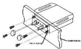
- Using the diagram below as reference install the remote behind the panel with the holes just drilled. Position the remote so the two knobs feed through panel and the LED's are in alignment with the holes drilled.
- Place the trim panel with the control labeling over the two shafts and secure it into place with the 4 screws provided.
- Push the two adjustment knobs onto the metal shafts.
- Connect one end of the GTX47 remote control wire (included) to the connector on the back of the remote control box.
- Run the wire back to the GTX47 main chassis and plug the remote control wire into the "Remote In" connector on the main chassis. Note: a standard 6-pin telephone extension cord may be used if more wire is needed for remote control connection. These extension cords can be purchased at many electronics or hardware stores.
Wiring Set-up
Audio Connections and Set-up: To reduce chances of vehicle-induced noise generated by radiation from other electrical equipment entering your sound system, use audiophile quality RCA extension cables whenever possible.
A great deal of time and labor will be saved if you invest in high quality signal cables before the system is installed, rather than upgrading after a noise problem surfaces.
Route the sound system's audio cables and power cables separately, as far away from each other as possible, in order to minimize chances of interference from high current power wires (such as power amp battery leads) being picked up by the audio cables.
JBL's GTX47 is a very versatile and flexible piece of equipment. To achieve this high degree of versatility, it was necessary to include many installer-defined controls that need be set for each different mode of operation.
After the GTX47 is mounted properly, it should be set up as described below.
Pre-amp Level Inputs:
- If the head unit has separate front and rear pre-amp outputs, connect each one using an extension cable to the front and rear inputs of the
GTX47. Set the Input Mode Switch (page 10, item 23) to the "Front & Rear" mode.
- If the head unit has a single pre-amp output, connect it to the front input of the GTX47 using an extension cable. Set the Input Mode Switch (page 10, item 23) to the "Front Only" mode.
Speaker Level Inputs — When the high level (speaker level) outputs of a cassette/CD are used to drive the GTX47, the signal goes into the GTX47 through a special 8 wire harness and connector (included). If extension wires must be used to connect the speaker output from the cassette/CD player to the GTX47 high (speaker) level inputs use 18 gauge speaker wire. Keep such extension wires as short as is practical and do not run them outside the passenger and trunk compartments Use the color code of the input wire harness and the cassette/CD player output wires to be sure the left/right channel orientation and the positive/negative orientation, of each connection is correct. For example, the left positive output of the cassette/CD player must be connected to the left positive input of the GTX47. The color code for the high level input wire harness is:
![graph TD A["Head Unit or signal processor with separate front & rear pre-outs"] --> B["Extension cables"] B --> C["Input MODE"] D["Head Unit or signal processor with a single pre-cut only"] --> E["Extension cable"] E --> F["Note: Use the Front input of the GTX47."] G["Input MODE"] --> H["Extension c…](/content/2026/06/1388609/images/83759156af389e662214d24cc47fafeeae293a16f37d4c9499a8e0aa551f38f0.jpg)
Left Front + White
Left Front - White/Black
Right Front + Grey
Right Front - Grey/Black
Left Rear + Green
Left Rear - Green/Black
Right Rear + Purple
Right Rear Purple/Black
If only two speaker level inputs are being used, use the front inputs and set the "Input Mode Switch" to "Front Only." This causes the front and rear crossover sections to be driven by the front input. If front and rear inputs are being used, set the "Input Mode Switch" to the "Front & Rear" position.
Bi-level Input Connections: Some head units feature two channels of preamp-level output and 2 channels of speaker-level output. To accommodate these units, you can connect the
2 channels of preamp-level signal to either the front or rear preamp input. The speaker level signal should then be connected to the opposite pair of speaker-level inputs. Use the level controls of the GTX47 to equalize the input sensitivity for front and rear so that the head-units fader can be left in the centered position in normal use.
OEM & Aftermarket Input Connections: Another option facilitated by the GTX47's "Universal Interface" circuitry is the connection of both a speaker-level and preamp-level source simultaneously. This allows an OEM amplified head unit to be connected to the speaker-level inputs and an aftermarket preamp-output CD player to be simultaneously connected. Both inputs will be mixed and sent to the GTX47 circuitry. To listen to either source, simply turn off the undesired source and turn on the desired one. No other signal switching is necessary. Note: If both head units are turned on at the same time, both will play through the system but no damage will occur. Simply turn off the unit you don't want to hear. Refer to "Appendix A" for remote turn-on switching details for this configuration.
IMPORTANT NOTE FOR RIGHT HAND DRIVE CARS: For countries which have right hand drive cars all input and output connections to the GTX47 should be reversed. Connect the left output of your CD/Cassette to
the right input of GTX47 and the right output of the CD/Cassette to the left input of the GTX47. Connect the right outputs of the GTX47 to the left inputs of the amplifier. Connect the left outputs of the GTX47 to the right inputs of the amplifier. (see System Configurations on page 28)
![graph TD A["Antenna"] --> B["Amplifier"] B --> C["Front IN"] B --> D["Input IN"] E["Subwoofer Amplifier"] --> F["INPUTS"] G["Output"] --> H["Input"] I["External"] --> J["Antenna"] K["External"] --> L["Amplifier"] M["External"] --> N["Front IN"] O["External"] --> P["Input IN"]](/content/2026/06/1388609/images/868fb559995f678fabf76d553f0008674ec23621543f81d85a6504a9f48759e8.jpg)
Two-way Crossover Connection
- Connect the Subwoofer amplifier to the Low output. Connect the Midrange/Tweeter amplifier to the "FRONT HIGH" or "REAR HIGH" output jacks.
- Set the "LOW," "FRONT HIGH," and "REAR HIGH" switches as necessary. See the CONTROLS and ADJUSTMENTS sections for details. Note the "HIGH" multiplier switch should be set to the "+20" position.
- Set the crossover point on the "LOW," "FRONT HIGH" and /or "REAR HIGH" outputs as described in the ADJUSTMENTS section.
Adjust the Tweeter/Midrange and Subwoofer amplifier gains and the GTX47 Front and Rear Channel gains as necessary to achieve proper system balance as described in the ADJUSTMENTS section.
![graph TD A["Input Signal"] --> B["Amplifier"] B --> C["Front In"] B --> D["Rear In"] B --> E["Output"] F["Input Signal"] --> G["Amplifier"] G --> H["Front In"] G --> I["Rear In"] G --> J["Output"] K["Input Signal"] --> L["Amplifier"] L --> M["Front In"] L --> N["Rear In"] L --> O["Output"] P["Input…](/content/2026/06/1388609/images/a3cd1412fc36d80240feb7c64b81d8be074341004bd3e2f074975823ee9ab8c6.jpg)
Three-way Crossover Connection
- Connect the Subwoofer amplifier to the Low output. Connect the Midwoofer amplifier to the "FRONT MID 1" or "REAR MID 1" output jacks of the GTX47 (see the diagram). Connect the Tweeter amplifier to the "FRONT HIGH" or "REAR HIGH" output jacks.
- Set the "LOW," "FRONT MID 1," "REAR MID 1," "FRONT HIGH," and "REAR HIGH" switches as necessary. See the CONTROLS and ADJUSTMENTS sections for details on setting these switches.
- Set the crossover point on the "LOW," "FRONT MID 1," "REAR MID 1," "FRONT HIGH," and "REAR HIGH" outputs as described in the ADJUSTMENTS section. Adjust the
Tweeter, Midwoofer, and Subwoofer amplifier gains and the GTX47 Front and Rear Channel gains as necessary to achieve proper system balance as described in the ADJUSTMENTS section.
![graph TD A["Transistors"] --> B["Microcontroller Amplifier"] A --> C["Subcoater Amplifier"] B --> D["Tweater Amplifier"] B --> E["Front IN REAR IN"] B --> F["Front IN REAR IN"] C --> G["Front IN REAR IN"] C --> H["Front IN REAR IN"] C --> I["Front IN REAR IN"] C --> J["Front IN REAR IN"] C --> K["Fr…](/content/2026/06/1388609/images/9351d0bf358c2f75ad6fa1cfaa7b8931d2842354a26cf976adb13866e827f9c2.jpg)
Four-way Crossover Connection
-
Connect the Subwoofer amplifier to the Low output. Connect the Midwoofer amplifier to the "FRONT MID 1" or "REAR MID 1" output jacks of the GTX47 (see the diagram). Connect the Midrange amplifier to the "FRONT MID 2" or "REAR MID 2" output jacks of the GTX47 (see the diagram). Connect the Tweeter amplifier to the "FRONT HIGH" or "REAR HIGH" output jacks.
-
Set the "LOW," "FRONT MID 1," "REAR MID 1," "FRONT MID 2," "REAR MID 2," "FRONT HIGH," and "REAR HIGH" switches as necessary. See the CONTROLS and ADJUSTMENTS sections for details on setting these switches.
- Set the crossover point on the "LOW," "FRONT MID 1," "REAR MID 1," "FRONT MID 2," "REAR MID 2," "FRONT HIGH," and "REAR HIGH" outputs as described in the ADJUSTMENTS section. Adjust the Tweeter, Midrange, Midwoofer, and Subwoofer amplifier gains and the GTX47 Front and Rear Channel gains as necessary to achieve proper system balance as described in the ADJUSTMENTS section.
JBL
Wiring and Set-Up
Power Connections:
CAUTION: ALWAYS DISCONNECT THE VEHICLE BATTERY'S NEGATIVE (-) TERMINAL BEFORE STARTING ANY WIRING CONNECTIONS.
Use the diagram below.
To insure a low impedance path from the vehicle's battery to the GTX47, 12-gauge or larger wire should be used to extend the battery (+) or ground wires.
A 3-Amp inline fuse (not included) should be used as close as possible to the battery's (+) terminal to protect the vehicle and the system.
All audio components should be grounded to a common point on the chassis. This grounding point must be verified as a true ground point by checking its continuity with the battery's (-) terminal, using an ohmmeter. There should be less than .1 ohm. The battery's (+) terminal should be disconnected before making this measurement to guarantee its accuracy. It should also be free of paint and contaminants.

Adjustments
General Requirements:
The JBL GTX47 is a very precise and versatile piece of equipment. It should be adjusted by an auto sound specialist who possesses the knowledge and the tools to accomplish this task accurately. It would be helpful to use a Real Time Analyzer, or other audio measurement device such as TEF, MLSSA, IMP, LMS, etc., but it is not absolutely necessary.
- It is imperative to have easy access to the GTX47 while it is being adjusted. If it is to be mounted permanently in a location which will not allow easy access, it will be necessary to temporarily relocate the unit by using long audio and power extension wires.
- Before any adjustments can be made, all stereo system components (except for the GTX47) must be permanently mounted in their locations, and the passenger compartment should be completely reassembled, as removed door panels or seats will affect the frequency response of the vehicle's interior.
- The vehicle's doors should be closed and windows rolled up. This may require temporary relocation of the GTX47 outside the vehicle's passenger compartment (if it is to be permanently mounted there), using long extension wires.
- The trunk can be left open if the passenger compartment, including all the speakers and speaker enclosures, are sealed off from the trunk.
- Check the component speakers' specifications for their rated frequency response. The active crossover frequencies used for each speaker must fall within its frequency response. For example, a mid-bass woofer rated from 60Hz to 300Hz must not be driven with frequencies lower than 60Hz or higher than 300Hz. Otherwise, the sound quality will be severely degraded and speaker damage may also result. Therefore, tentatively adjust the GTX47 crossover points not to exceed the frequency response of the drivers, and remember to stay within these boundaries during the adjustment procedure.
Instrumentation Requirements & Set-up:
- It will be most convenient to have the GTX47 as close as possible to the RTA (or other device) during adjustments, as it is easier to monitor the changes made by each control.
- This RTA should cover at least 20Hz to 20kHz in at least one-octave increments. It should also possess the ability to analyze and display frequency response at 100dB or more Sound Pressure Level (SPL).
- As there are many different makes and models of Audio Analyzers, it would be impractical to define set-up procedures for a specific unit. Therefore, you will need to familiarize yourself with the particular model of the analyzer you will be using to adjust
JBL
the GTX47. The analyzer's owner's manual can provide all the necessary information.
- A high quality, calibrated microphone should be used with the analyzer. The analyzer manufacturer can recommend a suitable model. This microphone should have a calibrated response throughout the audio bandwidth (20Hz to 20kHz).
NOTE: Audio adjustments must be done in quiet surroundings. Noise from wind, traffic, or other car stereo systems will affect the analyzer readings and throw off the adjustments.
After all the general requirements are met, proceed as follows:
- Position the microphone on a microphone stand placed on the driver's seat, in the same position and height as the right ear of the driver.

- Connect the microphone to the RTA. Set the controls for non-weighting (flat) and greater than 100dB range.
Pre-adjustment Setup: Set all tone controls, balance and fader controls, and in-dash equalizer controls to their neutral or bypass positions. Place the Image Enhancer in the bypass mode by pulling the left knob on the remote control.
Before adjusting the levels of the system, you need to determine the maximum level capability of each of the components of the system. This will prevent equipment damage during the adjustment procedure and also will assure that you get maximum possible dynamic range with the least noise.
Step 1: Turn the gain controls on all of the amplifiers in the system and on the GTX47 all of the way down.
Step 2: While playing a clean-sounding tape or CD, gradually increase the volume control until you either hear distortion or you have turned the volume control up all of the way. If you hear distortion before the volume control is fully raised, you have reached the maximum undistorted output of your head unit. Turn down the volume control until the distortion disappears and do not exceed this setting either during setup or use.
Step 3: Leave the head unit in its maximum undistorted setting, and gradually increase the GTX47 front gain control until you either hear distortion or the gain is up all of the way. Repeat the procedure for the rear. If you are using bi-level connection and one output is significantly louder than the other,
reduce the setting of the louder pair of channels so that they are equal.
Step 4: In most systems, the front midrange speakers generally define the maximum system output. This is because they generally handle the most energy over the widest band of frequencies. With the frequency controls set to their approximate final settings, raise the amplifier gain controls for the channels driving the front midrange speakers (or front satellite speakers in 2-way systems) just to the point where distortion occurs. You can now reduce the head unit's level control to a comfortable level for subsequent adjustments.
Step 5: Raise the remaining amplifier gain controls until the system is approximately balanced by ear. We recommend the following order of adjustment: front midrange (or front main speakers in 2-way systems), front tweeters, front midbass, rear midrange (or rear satellites in 2-way systems), rear tweeters, rear midbass, subwoofer. If, during this step, any frequency range exhibits distortion at a lower setting than the front midrange, do not increase its gain further. Instead turn the other bands down to balance the system.
Adjustments Using Instruments:
- Tum the sound system on, verify that all components are functional, and place all controls such as Bass, Treble, Fader, Balance, In-dash equalizer controls (if any) in the neutral position. Place the Imaging
Enhancer circuit in bypass mode by pulling out the left knob on the remote. Also verify that the Input Mode Switch, Subwoofer Slope Switch, Subwoofer Stereo/Mono Switch, and Frequency Multiplier + Divider Switches are set as needed.
- Using a test CD or tape such as the IASCA Test Disk, select a "Pink Noise" track and set the volume control of the system for a nominal 90-100dB average sound pressure level.
Perform the following steps with all doors closed, windows rolled up, and the vehicle interior completely intact:
- This sound level will give you a display on the measurement instrument screen. This display is the frequency response of the total system (the sound system and the vehicle's interior together). It may look somewhat similar to the one shown below:

This display shows how many decibels of sound pressure exist at each frequency. A pleasant sounding system should have a smooth frequency response transition. Also, the relative balance between the different drivers' output levels must be correct.
Due to different component speaker efficiencies, power amplifier sensitivity, vehicle interior resonances, speaker and speaker enclosure nonlinearities or interior audio section frequency response, an unadjusted system may have many peaks and dips in its frequency response. The amplifiers connected to the GTX47 can be adjusted to balance the acoustical response and reduce other nonlinearities.
Certain frequency regions can also be boosted or cut to overcome road noise or to accommodate listener preferences by adjusting the amplifiers input gain controls.
-
If you are using a head unit with separate front and rear pre-outs, verify that the front and rear input mode is selected, and fade to the front. Make sure that the rear drivers are defeated. Remember to keep the vehicle doors and windows closed during adjustments.
-
Analyze the spectrum display on the RTA to detect any imbalances between the output levels of each component driver. For example, in the display shown, the Subwoofer's response is lower than the mid-bass driver and the mid-bass driver's response is lower than the midrange speaker.
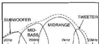
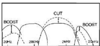
- Find out which speaker's output is about average when compared to the other bands. It is important to keep as many amplifier gain controls as possible set to the nominal position. This is to avoid clipping or poor signal-to-noise ratio problems common with excessive boost or cut values. In the example shown above, the mid-bass level is about average. Therefore the Subwoofers and Tweeter amplifier input gain controls must be boosted and the midrange level controls should be reduced.
-
While observing the RTA screen, adjust the amplifier input gain controls to properly shape and smooth out the level differences.
-
Adjust and fine-tune the crossover points for each region to further smooth out the acoustical response.
-
If you find that there are deep, narrow dips in response at any of the crossover points, which do not fill in as you adjust frequency, one of the drivers is out-of-phase at the crossover point. Use the phase switch to reverse the polarity of one of the drivers playing at that crossover point.
- If your head unit has a single pre-amp output only, skip to item 14.
- Fade to the rear, check for defeated front speakers, close all vehicle doors and windows, and repeat steps 5 through 9.
- Re-center the fader control, verify that all speakers are functional, close all the vehicle doors and windows, and repeat steps 5 through 10.
- The Low, Mid 1, Mid 2, or High amp gain control can now be fine-tuned for customer preferences such as more low bass or more emphasized highs.
- Using a high quality music source, carefully evaluate the sound and perform any additional adjustments as necessary.
NOTE: It is almost always necessary to dial-in additional sub-bass boost in order to overcome road noise which increases with the vehicle's speed.
- It will be necessary to test-drive the car, listen, and set the Subwoofer amp gain control to a compromised value between the optimum setting for stationary and freeway speed conditions.
Adjustments Without an RTA:
- The GTX47 should be temporarily moved to the driver's seat vicinity using long extension cables, and the adjustment should be done with the installer in the driver's seat.
- A high quality source material (music) with excellent sound quality and frequency response must be used.
- Turn the sound system on, verify that all components are functional, and place all controls such as Bass, Treble, Fader, Balance and In-dash equalizer controls (if any) in the center detente (neutral) position. Set the Imaging Enhancer Remote to bypass mode. Also verify that the Input Mode Switch, Low Stereo/Mono Switch, and the Multiplier Switches are set as needed.
Perform the following steps while seated in the driver's seat, with all doors, windows and trunk closed, and the vehicle interior completely intact.
-
If you are using a head unit with separate front and rear pre-outs, verify that the Front and Rear mode is selected, and fade to the front. Make sure that the rear drivers are defeated.
-
Listen carefully and try to find output level imbalance between the different component speakers.
- If such an imbalance exists, determine which output level is average (higher than some and lower than others).
- Try to keep the output level for the front midrange band in the position found in the pre-adjustment setup steps.
- Boost or cut the gain controls on the amplifier for each band as necessary to balance the sound.
- Adjust and fine-tune the crossover points for each region for the most smooth and pleasant sound. Do not exceed the frequency range recommended by the manufacturer of the speakers.
- Adjust the Phase Switches for the Mid 1, Mid 2 & High outputs to create the desired imaging characteristics.
- Adjust the Low output Phase Switch for the best low frequency response.
- If your head unit has a single pre-amp output only, skip to item 15.
-
Fade to the rear, check for defeated front speakers, close all vehicle doors and windows, and repeat steps 5 through 11.
-
Re-center the fader control, verify that all speakers are functional, close all the vehicle doors and windows, and repeat steps 5 through 11.
- The Low output, amplifier gain (or any other output) level can now be increased or decreased for listener preferences, such as more low bass or more emphasized highs.
- Using a high quality music source, carefully evaluate the sound and perform any additional adjustments as necessary.
NOTE: It is almost always necessary to dial-in additional sub-bass boost in order to overcome road noise which increases with the vehicle's speed.
- Test-drive the car, listen, and set the Subwoofer amplifier gain control to a compromised value between the optimum setting for stationary and freeway speed conditions.
Operation & Setup
After the installation is finished and all wiring is checked, proceed with the next few steps.
NOTE: Since the Imaging Enhancer in the GTX47 is primarily designed to optimize the sound stage for the driver, all tests should be performed while sitting in the driver's seat.
- The Power Indicator LED on the GTX47 main chassis should light up when the head unit is turned on.
- Make sure the "Front-ambience / Bypass / On" knob and "Rear-ambience / Driver / All" knobs are pushed in and rotated completely counterclockwise
- Play a selection which has vocals and good "center" channel information.
- Gently turn up the volume to a comfortable listening level. You should hear a very distinctive center image coming from the middle of your dashboard. If not, make sure the "Rear ambience / Driver / All" knob is pushed in to the "Driver" position for driver-optimized sound stage.
-
Proceed to push and pull the rear ambience knob to hear the effects of "Driver" and "All" modes. You should hear imaging coming from the middle of the dashboard when the knob is pushed in (Driver mode). You should hear stereo with ambience recovery when the knob is pulled out (All mode). If you find that the center imaging in the "Driver" position is slightly offset to the left or right side of the dashboard, the car-size switch allows optimization of the center imaging for large or standard size cars. This switch is located on the main chassis of the GTX47.
-
Slowly turn the "Front-Ambience" knob in the clockwise direction to increase ambience. You should begin to hear slight reverberation in the music and a sense of a widening front sound stage in both the "Driver" and "All" modes.
- Slowly turn the "Rear-Ambience" knob in the clockwise direction to increase rear ambience (only in systems with rear speakers). You should begin to hear an increase in reverberation and get a feeling of being in a very large auditorium. Note: The GTX47 converts the rear channels into a true rear-fill surround channels which cancels all center information (vocals, horns, etc.) and lets only true stereo and ambience information come out. This same process is used in more expensive "Surround Sound" systems used in theaters.
- Adjust the front and rear ambience as desired. For optimum center imaging, it is recommended that ambience be used sparingly on the front channels.
- To bypass the effects of the Imaging Enhancer in the GTX47, simply pull on the "Front-Ambience" knob until it clicks to the "bypass" position. The "Enhancer On" LED on the remote control panel with turn off and your sound system should revert back to normal stereo sound without ambience.
System Configurations
Typical GTX47 system configurations are shown below.
LEFT HAND DRIVE CAR (Connection shown for one speaker type only. Repeat similar connection for other speakers).
![graph LR A["CASSSETTE/CD"] --> B["GTX47"] B --> C["AMPLIFIER"] A -->|OUT FR FL RR RL| B B -->|IN FR FL RR RL| C B -->|OUT FR FL RR RL| C C --> D["+ -"] C --> E["+ -"] C --> F["+ -"]](/content/2026/06/1388609/images/f8ea442b690c35d8ffaff7037c48dfde81e9f2549e8adccb41ac33d6fe6514ee.jpg)
RIGHT HAND DRIVE CAR (Connection shown for one speaker type only. Repeat similar connection for other speakers).
![graph LR A["CASSETTE/CD"] -->|OUT FR FL RR RL| B["GTX47"] B -->|IN FR FL RR RL| C["AMPLIFIER"] C -->|IN FR FL RR RL| D[+ - + - + - + - + - + - + - + - + - + - + - + - + - + - + - + - + - + - + - + - + - + - + - + - + - + - + - + - + - + - + - + - + - + - + - + - + - + - + - + - + - + - + - + - + - +…](/content/2026/06/1388609/images/c55846731ee5a6419745a076a4ddf450d0ac792c2f9d3ff7272a0c906c4469a7.jpg)
NOTE: Right hand driver cars must reverse right and left inputs and outputs for proper functioning of the Imaging Enhancer.
In Case of Difficulty
Main chassis Remote-on light does not come on.
Remote-On light is on, but no sound is heard from some or all of the speakers
• Head unit is not on; turn the head unit on.
- Ground wire is disconnected or defective; check for continuity with an ohmmeter between GTX47's ground terminal and a known chassis ground point.
- Battery wire is disconnected or defective; check for approximately + 12 volts between GTX47's Battery and Ground terminals.
- Blown Fuse; check GTX47's 3A Fuse, located on the main chassis near the Battery terminal. If it is blown, replace it with an identical one. If the new fuse blows immediately, then check all the wiring connections. If no fault is found, consult your JBL dealer.
- Remote-on wire between the head unit and the GTX47 is disconnected or defective; check for +12 volts between GTX47 Remote-on connector and ground connector with the head unit on.
- Incorrect Switch Settings; Make sure that all switches are in their correct positions for your system configuration
- Defective or disconnected audio cables; check for continuity and replace if necessary.
- Incorrect Channel Gain Adjustment; Verify that the amplifier and GTX47 level controls are not turned completely down. If they are, sound output level may be very low and may give the impression that the system (or part of the system) is dead.
- Defective GTX47; Bypass the GTX47 by connecting its input and the dead output terminal's cables together. If the system becomes functional, the GTX47 may be defective. Consult your JBL dealer.
Alternator whine through the audio system with the engine running.
- Defective Head Unit, or other audio component; Check each component for wiring and operation.
- Ground loops; Connect grounds of all audio components to the same point on the vehicle chassis. Verify that this point is a true ground by checking for continuity with an ohmmeter between the ground point and the battery's.
If you want to talk to us about any problems, call JBL Customer Service at 1-800-645-7484 between 9AM and 5PM eastern time.
Appendix
If using two head units in "Wiring and Setup" Step 2, you will need to install isolation diodes as shown below to allow either head until to turn the system on without interference from the other.

- FEATURES
- THEORY OF OPERATION
- PASSIVE CROSSOVERS
- ACTIVE CROSSOVERS
- THEORY OF OPERATION – VIRTUAL CENTER IMAGE ENHANCER
- CONTROLS, CONNECTORS AND SWITCHES
- MOUNTING INSTRUCTIONS
- SCREW-DOWN MOUNTING
- REMOTE CHASSIS INSTALLATION
- IN-DASH REMOTE INSTALLATION
- WIRING SET-UP
- PRE-AMP LEVEL INPUTS
- TWO-WAY CROSSOVER CONNECTION
- THREE-WAY CROSSOVER CONNECTION
- FOUR-WAY CROSSOVER CONNECTION
- WIRING AND SET-UP
- ADJUSTMENTS
- GENERAL REQUIREMENTS
- INSTRUMENTATION REQUIREMENTS & SET-UP
- ADJUSTMENTS USING INSTRUMENTS
- ADJUSTMENTS WITHOUT AN RTA
- NOTE: IT IS ALMOST ALWAYS NECESSARY TO DIAL-IN ADDITIONAL SUB-BASS BOOST IN ORDER TO OVERCOME ROAD NOISE WHICH INCREASES WITH THE VEHICLE'S SPEED
- OPERATION & SETUP
- SYSTEM CONFIGURATIONS
- IN CASE OF DIFFICULTY
- APPENDIX
Marque : JBL
Modèle : GTX47
Catégorie : Équipement audio